1
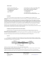
Technical data
- dimensions: 35mm x 18mm x 5mm
- RX plug: Futaba female, 22AWG, 300mm
- power supply from Rx: 3,0V – 24,0V
1 - 7 x (LiPo/Li-Ion/LiFe)
3 - 20 x (NiMh/NiCd)
- weight: 15,0 gram
- power supply ign. bat.: Futaba / JR male 22AWG, 150mm
- ignition plug: Futaba / JR female 22AWG, 150mm
- LED wire: 300mm, diode (fi)3mm ultra bright
- ign. power supply: 3,0V – 20,0V
1 - 7 x (LiPo/Li-Ion/LiFe)
3 - 16 x (NiMh/NiCd)
- max current: 5A continous, 16A temporarily
- current drain when OFF: 1,8uA at 6,0V; 20,0uA at 16,0V
Installation
Device must be installed inside the fuselage. Wire connector with the RCVR description is plugged in the RC
receivers free proportional channel. Although the device is resistant to vibrations, but if possible you must install them on elastic
foam plate.
By default Ignition circuit is powered from the ignition battery (output with the BAT description). Voltage stabilizer (if needed)
should be applied if the level of battery volage is higher than acceptable input voltages for ignition unit . Stabilizer can be installed
both before as well as behind the Optical Kill Switch. (putting it at the output – betweend ignition module and kill switch eliminates
need of using mechanical switch) Ignition unit is connected to the output with IGN description and it is powered directly from it.
Signaling LED diode must be installed in the the visible place, it provides useful information about operating status of kill switch.
Because the main task of Optical Kill Switch is electric separation of the RC receiver circuits from ignition circuits, should
make every effort so that remaining wires of these circuits won’t mix with each other and were possible as farthest from each other.
The only element connective both circuits should be the Optical Kill Switch.
Possiblity to power ignition module from receiver battery.
By default the device is using power from receiver for system logic and from independent battery to power the
ignition module. Those circuits are double opto-isolated from each other. However it is possible to power the ignition module also
from receiver, without using extra battery.
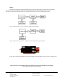
To do so it it necessarily to remove heat shrink tube and solder together two pairs of pads (bottom side under the BAT and IGN
wires, mrked as [B] and [C] at the end of this manual). From now the battery input wire is not being used.
First run
During first run it is necessary to carry out the calibration of channel in which the Optical Kill Switch is plugged, analogy
like during the regulation of servomechanism end points. The Kill Switch recognizes 3 levels of the input signal from the RC receiver,
corresponding to 3 operation status (see Figure below).
Calibration procedure along with adjusting of Fail-Safe level should proceed as follows:
Set the value of signal on the RC receiver channel in which Kill Switch is plugged on value in which the device operates in the FailSafe mode (diode will start to blink – short red impulses).
Program the transmitter / receiver so that this value will be generated during the break of connection in the Fail-Safe mode
(procedure of programming the receiver in F/S is different for all sort of transmitters producers, we recommend to look into the
SETLO
os. Przyjaźni 13/80
61-687 Poznań, POLAND
www.setlo.com
Technical support:
Tel.: +48 535 792 010
e-mail: [email protected]