1
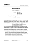
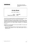
Microcontroller Components Errata Sheet December 23, 1998 / Release 1.1 Device: SAB 80C166W-M SAB 80C166W-M-T3 SAB 80C166W-M-T4 Stepping Code / Marking: ES-DA, DA Package: MQFP-100 This Errata Sheet describes the deviations from the current user documentation. The classification and numbering system is module oriented in a continual ascending sequence over several derivatives, as well already solved deviations are included. So gaps inside this enumeration could occur. The current documentation is: Data Sheet: SAB 80C166W/83C166W Data Sheet 02.94 User’s Manual: SAB80C166/83C166 User’s Manual 06.90/08.97, including Addendum to SAB80C166/83C166 User’s Manual 9.90 Instruction Set Manual 12.97 Version 1.2 Note: Devices marked with EES- or ES are engineering samples which may not be completely tested in all functional and electrical characteristics, therefore they should be used for evaluation only. The specific test conditions for EES and ES are documented in a separate Status Sheet. Change summary to Errata Sheet Rel.1.0 for devices with stepping code/marking ES-DA, DA: • • • • • • • • new format, including standard problem identification codes of C166 microcontroller family (in parenthesis) PEC Transfers after JMPR (problem 34 (BUS.18)) Modifications of ADM field while bit ADST = 0 (problem 33 (ADC.11)) Execution of PWRDN instruction while pin NMI# = high (problem 32 (PWRDN.1)) Arithmetic Overflow by DIVLU instruction (problem 30 (CPU.17)) Non-multiplexed bus without read-write delay (problem 29 (BUS.15)) Input leakage current (Ioz1) at Port 5 (DC problem 11 (DC.IOZ1.2)) Problem History: truncated to CB-step as last device step included Semiconductor Group Errata Sheet, SAB 80C166W, DA, 1.1, Mh - 1 of 12 - Functional Problems: Problem 34 (BUS.18): PEC Transfers after JMPR instruction Problems may occur when a PEC transfer immediately follows a taken JMPR instruction when the following sequence of 4 conditions is met (labels refer to following examples): 1. in an instruction sequence which represents a loop, a jump instruction (Label_B) which is capable of loading the jump cache (JMPR, JMPA, JB/JNB/JBC/JNBS) is taken 2. the target of this jump instruction directly is a JMPR instruction (Label_C) which is also taken and whose target is at address A (Label_A) 3. a PEC transfer occurs immediately after this JMPR instruction (Label_C) 4. in the following program flow, the JMPR instruction (Label_C) is taken a second time, and no other JMPR, JMPA, JB/JNB/JBC/JNBS or instruction which has branched to a different code segment (JMPS/CALLS) or interrupt has been processed in the meantime (i.e. the condition for a jump cache hit for the JMPR instruction (Label_C) is true) In this case, when the JMPR instruction (Label_C) is taken for the second time (as described in condition 4 above), and the 2 words stored in the jump cache (word address A and A+2) have been processed, the word at address A+2 is erroneously fetched and executed instead of the word at address A+4. Note: the problem does not occur when - the jump instruction (Label_C) is a JMPA instruction - the program sequence is executed from internal ROM/Flash Example1: Label_A: instruction x ; Begin of Loop instruction x+1 ..... Label_B: JMP Label_C ; JMP may be any of the following jump instructions: JMPR cc_zz, JMPA cc_zz, JB/JNB/JBC/JNBS ; jump must be taken in loop iteration n ; jump must not be taken in loop iteration n+1 ..... Label_C: JMPR cc_xx, Label_A ; End of Loop ; instruction must be JMPR (single word instruction) ; jump must be taken in loop iteration n and n+1 ; PEC transfer must occur in loop iteration n Example2: Label_A: instruction x ; Begin of Loop1 instruction x+1 ..... Label_C: JMPR cc_xx, Label_A ; End of Loop1, Begin of Loop2 ; instruction must be JMPR (single word instruction) ; jump not taken in loop iteration n-1, i.e. Loop2 is entered ; jump must be taken in loop iteration n and n+1 ; PEC transfer must occur in loop iteration n ..... Label_B: JMP Label_C ; End of Loop2 ; JMP may be any of the following jump instructions: JMPR cc_zz, JMPA cc_zz, JB/JNB/JBC/JNBS ; jump taken in loop iteration n-1 Semiconductor Group Errata Sheet, SAB 80C166W, DA, 1.1, Mh - 2 of 12 - A code sequence with the basic structure of Example1 was generated e.g. by a compiler for comparison of double words (long variables). Workarounds: 1. use a JMPA instruction instead of a JMPR instruction when this instruction can be the direct target of a preceding JMPR, JMPA, JB/JNB/JBC/JNBS instruction, or 2. insert another instruction (e.g. NOP) as branch target when a JMPR instruction would be the direct target of a preceding JMPR, JMPA, JB/JNB/JBC/JNBS instruction, or 3. change the loop structure such that instead of jumping from Label_B to Label_C and then to Label_A, the jump from Label_B directly goes to Label_A. Notes on compilers: In the Hightec compiler beginning with version Gcc 2.7.2.1 for SAB C16x – V3.1 Rel. 1.1, patchlevel 5, a switch –m bus18 is implemented as workaround for this problem. In addition, optimization has to be set at least to level 1 with –u1. The Keil C compiler versions < V4.0 and run time libraries do not generate or use instruction sequences where a JMPR instruction can be the target of another jump instruction, i.e. the conditions for this problem do not occur. In V4.0, the problem may occur when optimize (size or speed, 7) is selected. Lower optimization levels than 7 are not affected. In V4.01, a new directive FIXPEC is implemented which avoids this problem. In the TASKING C166 Software Development Tools, the code sequence related to problem BUS.18 can be generated in Assembly. The problem can also be reproduced in C-language by using a particular sequence of GOTOs. With V6.0r3, TASKING tested all the Libraries, C-startup code and the extensive set of internal testsuite sources and the BUS.18 related code sequence appeared to be NOT GENERATED. To prevent introduction of this erroneous code sequence, the TASKING Assembler V6.0r3 has been extended with the CHECKBUS18 control which generates a WARNING in the case the described code sequence appears. When called from within EDE, the Assembler control CHECKBUS18 is automatically 'activated'. Problem 33 (ADC.11): Modifications of ADM field while bit ADST = 0 The A/D converter may unintentionally start one auto scan single conversion sequence when the following sequence of conditions is true: (1) the A/D converter has finished a fixed channel single conversion of an analog channel n > 0 (i.e. contents of ADCON.ADCH = n during this conversion) (2) the A/D converter is idle (i.e. ADBSY = 0) (3) then the conversion mode in the ADC Mode Selection field ADM is changed to Auto Scan Single (ADM = 10b) or Continuous (ADM = 11b) mode without setting bit ADST = 1 with the same instruction Under these conditions, the A/D converter will unintentionally start one auto scan single conversion sequence, beginning with channel n-1, down to channel number 0. In case the channel number ADCH has been changed before or with the same instruction which selected the auto scan mode, this channel number has no effect on the unintended auto scan sequence (i.e. it is not used in this auto scan sequence). Semiconductor Group Errata Sheet, SAB 80C166W, DA, 1.1, Mh - 3 of 12 - Note: When a conversion is already in progress, and then the configuration in register ADCON is changed, - the new conversion mode in ADM is evaluated after the current conversion - the new channel number in ADCH and new status of bit ADST are evaluated after the current conversion when a conversion in fixed channel conversion mode is in progress, and after the current conversion sequence (i.e. after conversion of channel 0) when a conversion in an auto scan mode is in progress. In this case, it is a specified operational behaviour that channels n-1 .. 0 are converted when ADM is changed to an auto scan mode while a fixed channel conversion of channel n is in progress (see e.g. 80C166 User’s Manual, 06.90, p.8-58) Workaround: When an auto scan conversion is to be performed, always start the A/D converter with the same instruction which sets the configuration in register ADCON. Problem 32 (PWRDN.1): Execution of PWRDN Instruction while pin NMI# = high When instruction PWRDN is executed while pin NMI# is at a high level, power down mode should not be entered, and the PWRDN instruction should be ignored. However, under the conditions described below, the PWRDN instruction may not be ignored, and no further instructions are fetched from external memory, i.e. the CPU is in a quasi-idle state. This problem will only occur in the following situations: a) the instructions following the PWRDN instruction are located in external memory, and a multiplexed bus configuration with memory tristate waitstate (bit MTTCx = 0) is used, or b) the instruction preceding the PWRDN instruction writes to external memory, and the instructions following the PWRDN instruction are located in external memory. In this case, the problem will occur for any bus configuration. Note: the on-chip peripherals are still working correctly, in particular the Watchdog Timer will reset the device upon an overflow. Interrupts and PEC transfers, however, can not be processed. In case NMI# is asserted low while the device is in this quasi-idle state, power down mode is entered. Workaround: Ensure that no instruction which writes to external memory precedes the PWRDN instruction, otherwise insert e.g. a NOP instruction in front of PWRDN. When a multiplexed bus with memory tristate waitstate is used, the PWRDN instruction should be executed out of internal RAM. Semiconductor Group Errata Sheet, SAB 80C166W, DA, 1.1, Mh - 4 of 12 - Problem 30 (CPU.17): Arithmetic Overflow by DIVLU instruction For specific combinations of the values of the dividend (MDH,MDL) and divisor (Rn), the Overflow (V) flag in the PSW may not be set for unsigned divide operations, although an overflow occurred. E.g.: MDH F0F0 MDL Rn MDH MDL 0F0Fh : F0F0h = FFFF FFFFh, but no Overflow indicated! (result with 32-bit precision: 1 0000h) The same malfunction appears for the following combinations: n0n0 0n0n : n0n0 n00n 0nn0 : n00n n000 000n : n000 n0nn 0nnn : n0nn where n means any Hex Digit between 8 ... F i.e. all operand combinations where at least the most significant bit of the dividend (MDH) and the divisor (Rn) is set. In the cases where an overflow occurred after DIVLU, but the V flag is not set, the result in MDL is equal to FFFFh. Workaround: Skip execution of DIVLU in case an overflow would occur, and explicitly set V = 1. E.g.: CMP Rn, MDH JMPR cc_ugt, NoOverflow ; no overflow if Rn > MDH BSET V ; set V = 1 if overflow would occur JMPR cc_uc, NoDivide ; and skip DIVLU NoOverflow: DIVLU Rn NoDivide: ... ; next instruction, may evaluate correct V flag Note: - the KEIL C compiler, run time libraries and operating system RTX166 do not generate or use instruction sequences where the V flag in the PSW is tested after a DIVLU instruction. - with the TASKING C166 compiler, for the following intrinsic functions code is generated which uses the overflow flag for minimizing or maximizing the function result after a division with a DIVLU: _div_u32u16_u16() _div_s32u16_s16() _div_s32u16_s32() Consequently, an incorrect overflow flag (when clear instead of set) might affect the result of one of the above intrinsic functions but only in a situation where no correct result could be calculated anyway. These intrinsics first appeared in version 5.1r1 of the toolchain. Libraries: not affected Semiconductor Group Errata Sheet, SAB 80C166W, DA, 1.1, Mh - 5 of 12 - Problem 29 (BUS.15): Non-multiplexed Bus without Read/Write Delay When a non-multiplexed external bus is used in the configuration without Read/Write Delay and with normal (non-extended) ALE, i.e. when - bit SYSCON.RWDC = 1 (access controlled by SYSCON), or - bit BUSCON1.RWDC1 = 1 and BUSCON1.ALECTL1 = 0 (access controlled by BUSCON1, then both the RD# and WR# signal may be driven low during a read or instruction fetch cycle which follows a write cycle. Note that this problem depends on supply voltage and ambient temperature, and that it may only occur in an area around Vccmax (5.5 V) and TAmin (-40 °C) Note: in a multiplexed bus configuration, in general always Read/Write Delay must be used (i.e. bit RWDCx must remain at its default state ’0’), otherwise an external bus contention will occur. Therefore, all systems which do not use a non-multiplexed external bus configuration are not affected by this problem. Workaround: Use a non-multiplexed bus configuration where - bit SYSCON.RWDC = 0, and - bit BUSCON1.RWDC1 = 0 when BUSCON1.RWDC1 = 0 Problem 28 (CPU.11): Stack Underflow Trap during Restart of interrupted Multiplication Wrong multiply results may be generated when a STUTRAP (stack underflow) is caused by the last implicit stack access (= pop PSW) of a RETI instruction which restarts an interrupted MUL/MULU instruction. No problem will occur in systems where the stack overflow/underflow mechanism is not used, or where an overflow/underflow will result in a software reset. Workaround 1: Avoid a stack overflow/underflow e.g. by - allocating a larger internal system stack (via field STKSZ in register SYSCON), or - reducing the required stack space by reducing the number of interrupt levels, or - testing in each task procedure whether a stack underflow is imminent, and anticipating the stack refill procedure before executing the RETI instruction. Workaround 2 (may be selected if no divide operations are used in an interruptible program section): In each interrupt service routine (task procedure), always clear bit MULIP in the PSW and set register MDC to 0000h. This will cause an interrupted multiplication to be completely restarted from the first cycle after return to the priority level on which it was interrupted. In case that an interrupt service routine is also using multiplication, only registers MDH and MDL must be saved/restored when using this workaround, while bit MULIP and register MDC must be set to zero. Semiconductor Group Errata Sheet, SAB 80C166W, DA, 1.1, Mh - 6 of 12 - Workaround 3 (may be selected when a program is generated with C compilers): Select the compiler option which prevents MULx instructions to be interrupted. In the BSO Tasking C166, the -BM option in combination with the ’protected’ libraries (lib\p directory) should be used. Note that in this case - both MUL and DIV will be protected against interrupts - BCLR IEN is used to temporarily disable interrupts; however, a (low priority) interrupt may still be acknowledged before the protection is in effect. This may affect the real time behaviour of the system, since this interrupt routine is now uninterruptible. - the NMI# (class A trap) may still interrupt a multiplication, so this method should not be used when the NMI# is used. Workaround 4 (may be selected when none of the previous workarounds can be used): a) if no NMI# is used: SCXT PSW, #0Fxy0h ; x = 8h if HLDEN = 0, x = 0Ch if HLDEN = 1 ; y = 0h if USR0 = 0, y = 4h if USR0 = 1 NOP NOP MULx Rm, Rn POP PSW Note: It is not recommended to use BCLR IEN to disable interrupts due to pipeline effects which may lead to an unexpected order of interrupt nesting (see also Application Note AP160902 ’How to make instruction sequences uninterruptible’ on http://www.siemens.de/semiconductor/products/ics/34/pdf/ap160902.pdf). b) if NMI# is used: the multiply operation must be executed on the class A trap level. This may be achieved e.g. with the following sequence, where the stack overflow trap routine is shared with a multiply routine: Main Program: DataSection DataSection MainRB CodeSection MainProc ... MOV MOV MOV SECTION BIT Atomic DBIT GLOBAL Atomic ENDS ; flag for uninterruptible sequence ; may be used by different task procedures REGDEF R2-R4 COMMON = Para, R0-R1 PRIVATE SECTION CODE PROC TASK INTNO = 0; e.g. task which is executed after reset R2, multiplicand ; parameters for multiply routine R3, multiplier ; R4, #SOF AtomicMUL ; segment offset of procedure AtomicMUL, required as ; parameter if both MUL and MULU are used BSET STKOF ; set STKOF flag to force trap BSET Atomic ; flag uninterruptible sequence ... Note: When trap flags are set by software, 1 (at least) or 2 (at most) instructions following the instruction which set the trap flag may be executed before the trap is entered. Semiconductor Group Errata Sheet, SAB 80C166W, DA, 1.1, Mh - 7 of 12 - Trap Service Routine: EXTERN Atomic:BIT StackOvRB REGDEF R0-R2 COMMON = Para, R2-R3 PRIVATE CodeSec SECTION CODE StackOvTrap PROC Task INTNO = 4 ; stack overflow task SCXT CP, #StackOvRB ; switch registerbank BCLR STKOF ; clear trap flag JBC Atomic, SHORT MultiplyService ; test and clear Atomic flag ExceptionTrapService: ... ; code for exception trap service ... ; JMP Continue ; end of exception trap service MultiplyService: CALLI cc_UC, [R2] Continue: POP CP RETI StackOvTrap ENDP ; execute AtomicMUL or AtomicMULU, specified by R2 ; restore previous registerbank ; return from trap service routine Problem 26 (CPU.9: PEC Transfers during instruction execution from Internal RAM When a PEC transfer occurs after a jump with cache hit during instruction execution from internal RAM (locations 0FA00h - 0FDFFh), the instruction following the jump target instruction may not be (correctly) executed. This problem occurs when the following sequence of conditions is true: i) a loop terminated with a jump which can load the jump target cache (possible for JMPR, JMPA, JB, JNB, JBC, JNBS) is executed in the internal RAM ii) at least two loop iterations are performed, and no JMPS, CALLS, RETS, TRAP, RETI instruction or interrupt is processed between the last and the current iteration through the loop (i.e. the condition for a jump cache hit is true) iii) a PEC transfer is performed after the jump at the end of the loop has been executed iv) the jump target instruction is a double word instruction Workaround 1: Place a single word instruction (e.g. NOP) at the jump target address in the internal RAM. Workaround 2: Use JMPS (unconditional) or JMPI (conditional) instructions at the end of the loop in the internal RAM. These instructions will not use the jump cache. Problem 24 (CPU.7): Warm HW Reset (Pulse Length < 1032 TCL) In case a HW reset signal with a length < 1032 TCL (25.8 µs @ 20 MHz) is applied to pin RSTIN#, the internal reset sequence may be terminated before the specified time of 1032 TCL, and not all SFRs may be correctly reset to their default state. Instead, they maintain the state which they had before the falling edge of RSTIN#. The problem occurs when the falling edge of the (asynchronous) external RSTIN# signal is coincident with a specific internal state of the controller. The problem will statistically occur more frequently when waitstates are used on the external bus. Workaround: Extend the HW reset signal at pin RSTIN# (e.g. with an external capacitor) such that it stays below V IL (0.2 Vcc - 0.1 V) for at least 1032 TCL. Semiconductor Group Errata Sheet, SAB 80C166W, DA, 1.1, Mh - 8 of 12 - 'HYLDWLRQVIURP(OHFWULFDODQG7LPLQJ6SHFLILFDWLRQ The following table lists the deviations of the DC/AC characteristics from the specification in the 80/83C166W Data Sheet 02.94: Problem 11: Input Leakage Current (Ioz1) at Port 5 The input leakage current (Ioz1) of some devices can deviate from the actual specified limit value of ±200 nA at input voltages (Vin) close to 0 V. High ambient temperature and maximum supply voltage lead to a maximum increase of the leakage current. The following equation describes the behavior of the leakage current for input voltages between 0 V and 200 mV and covers all specified operating conditions. This equation stands for an exponential decrease from ±10 µA leakage current at Vin = 0 V to ±200 nA at Vin = 200 mV. Vcc = 5 V ±10 % Tamin < Ta < Tamax Tamin, Tamax see Data Sheet Input Voltage (Vin) Input Leakage Current (Ioz1) 0 < Vin < 200 mV Ioz1 = ±a*e(b*Vin) a = 10 µA; -1 b = -0,0196 mV 1 200 mV < Vin < Vcc ) Ioz1 = ±200 nA 1 ) Note: For input voltages above 200 mV the input leakage specification remains unchanged. The figure below shows the input leakage current as function of the input voltage. ,QSXW/HDNDJH&XUUHQW,R]DW3RUW 10,00 @ D > _ ] R , _ 1,00 0,10 0,00 1,00 2,00 3,00 4,00 5,00 9LQ>9@ Semiconductor Group Errata Sheet, SAB 80C166W, DA, 1.1, Mh - 9 of 12 - History List (since device step CB) Functional Problems Functional Problem Short Description 34 / BUS.18 PEC Transfers after JMPR Instruction 33 / ADC.11 Modifications of ADM field while bit ADST = 0 (problem only in Dx-steps, problem not included in earlier steps of 80/83C166/W) Fixed in step 32 / PWRDN.1 Execution of PWRDN Instruction while pin NMI# = high 31 / CPU.16 Data read access with MOVB [Rn], mem instruction to internal ROM (problem only in ROM version 83C166/W and Flash/bondout versions) 30 / CPU.17 Arithmetic Overflow by DIVLU instruction 29 / BUS.15 Non-multiplexed bus without read-write delay 28 / CPU.11 Stack Underflow during Restart of Interrupted Multiply 27 / CPU.10 Bit protection for register TFR 26 / CPU.9 PEC Transfers during instruction execution from Internal RAM 25 / INT.7 Bit Instructions on Interrupt Control Registers 24 / CPU.7 Warm Hardware Reset (pulse length < 1032 TCL) 23 / ASC.2 Serial Channel Overrun Error DA 22 / ADC.4 A/D Converter Overrun Error DA 21 / CPU.5 Result Forwarding by BFLDL/BFLDH DA 20 / ADC.3 Restart of A/D Converter DA 19 / CPU.4 Jump with Cache Hit after branch from internal ROM/Flash DA 18 Watchdog Timer reset in Idle Mode CB 17 Interrupted multiplication with interrupt after RETI CB DA DA 1) The stepping code which is listed in column ’Fixed in step’ refers to all qualification steps (early engineering samples (EES), engineering samples (ES)), unless specifically stated otherwise. Notes: 1) fixed in all devices with stepping code/marking CB except for CB-ES AC/DC Deviations AC/DC Deviation Short Description Fixed in step 11 / DC.IOZ1.2 Input Leakage Current (Ioz1) at Port 5 Semiconductor Group Errata Sheet, SAB 80C166W, DA, 1.1, Mh - 10 of 12 - Appendix In this appendix, some architectural items are described which are not yet documented in a very detailed manner in the current release of the SAB 80C166 User’s Manual and/or Data Sheet. In the next revisions, these items will be integrated. 1.) Synchronous READY#: When the ’Synchronous Ready’ mode has been selected for external memory accesses, for example by the following instruction sequence, BCLR DP3.14 ; Pin direction = INPUT BCLR SYSCON.3 ; Select ’Synchronous Ready’ Mode BSET RDYEN ; Enable READY function this mode will only work properly if the system clock output pin CLKOUT is enabled in addition (P3.15 = 1, DP3.15 = 1, SYSCON.CLKEN = 1). The reason for this is that the system clock is normally required externally as synchronous reference signal. 2.) MDL Register: From the CA-step on, the MDL register may also be read via a short ’reg’ addressing mode immediately after a divide instruction. This means that the note concerning the pipeline side effect in the Appendix of previous Errata Sheets must no longer be taken into account. 3.) Uninterruptible Instruction Sequences: To be absolutely sure that an instruction (sequence) can not be interrupted, at least 2 instructions (e.g. NOPs) must be programmed after the instruction disabling the interrupts, as shown in the following example (see also the application note AP160902 ’How to make instruction sequences uninterruptible’ on http://www.siemens.de/semiconductor/products/ics/34/pdf/ap160902.pdf). BCLR IEN NOP NOP ... ; or other appropriate instructions ; Start of the uninterruptible range 4.) JBC/JNBS Instructions: From the CA-step on, the operation of the semaphore instructions JBC/JNBS has been changed such that these instructions only write back to the bit to be tested when the branch condition is true. This modification has no effect on bits in the internal RAM or on SFR bits which are not modified by hardware. However, the use of these instructions on SFR bits which may be changed both by hardware and software is now directly possible without any special considerations (see also the application note on JBC/JNBS in the SAB 80C166 Family ApNotes collection). The modified operation of the JBC/JNBS instructions is as follows: JBC: JNBS: IF (bit) = 1 THEN (bit) := 0 (IP) := target ELSE next instruction END IF IF (bit) = 0 THEN (bit) := 1 (IP) := target ELSE next instruction END IF 5.) P3.12 (BHE#) in Single Chip Mode: From the DA-step on, when the Single Chip mode is selected during reset (pin BUSACT# = 1, EBC0 = EBC1 = 0), this pin is also floating (and no longer driving a low level) after reset like all other port pins. This means that the note concerning this pin in the Appendix of previous Errata Sheets must no longer be taken into account. 6.) Power Down Mode: When driving the XTAL1 input with an external clock source, XTAL1 must be held at VCC to VCC-0.1V in order to meet the IPD specification of 50 µA. Semiconductor Group Errata Sheet, SAB 80C166W, DA, 1.1, Mh - 11 of 12 - Functional Improvements/Compatibility Issues In the following sections, the functional improvements have been implemented in the 80C166/83C166/W beginning with the DA-step are described, and compatibility issues related with these improvements are discussed. These improvements are already included in the CC-step of the bondout version 80C166E and the flash version 88C166/W. In general, all of these improvements are hardware and software upward compatible. 1. Serial Channels ASCx: Start Bit detection (async mode) Reception of data in the asynchronous mode of ASCx is initiated whenever a high to low transition (start bit) is detected at the respective RxD pin. When RxD stays at a low level during and after the bit time of the stop bit (BREAK situation), a receive interrupt and a framing error is generated, and no further data frames are received until the next high to low transition at pin RxD signals the start of a new data frame. This means that only one incorrect data frame is received at the beginning of such a BREAK situation. In the previous steps, reception was already initiated when a low level was detected at RxD. In case RxD stayed low during and after the stop bit time slot, a receive interrupt and a framing error was generated, but reception of further data frames proceeded, including generation of receive interrupts and framing errors, until RxD went to a high level (end of BREAK situation). This means that several incorrect data frames could be received during such a BREAK situation. In systems where the RxD line correctly returns to a high level while no data are transmitted (i.e. no BREAK situations occur), there will be no differences between the current step and previous steps of the 80C166. In systems where RxD may go to a low level during and after the stop bit time slot, the functionality improvement of the start bit detection in the current step may lead to simpler software implementations of detecting the end of such a BREAK situation. 2. Serial Channels ASCx: Receive data hold time (sync mode) In the synchronous mode of ASCx, the timing for the receive data on the respective RxD line in relation to the shift clock which is output on the corresponding TxD line is as follows: Input data setup time to shift clock rising edge: 4 TCL (100 ns @ 20 MHz) Input data hold time after shift clock rising edge: 0.0 us In previous steps, this timing was as follows: Input data setup time to shift clock rising edge: not relevant Input data hold time after shift clock rising edge: 1/4 of shift clock cycle time This functionality improvement is upward compatible, since a transmitter which is connected to the RxD line will normally change its data with the falling edge of the shift clock, such that the timing requirements of all steps of the 80C166 are met. Application Support Group, Munich Semiconductor Group Errata Sheet, SAB 80C166W, DA, 1.1, Mh - 12 of 12 -