1
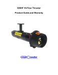
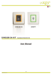
Table of Contents
Abstract . . . . . . . . . . . . . . . . . . . . . . . . . . . . . . . . . . . . . . . . . . . . . . . . . . . . . . . . . . . . . . . . . . . . . 2
Budget . . . . . . . . . . . . . . . . . . . . . . . . . . . . . . . . . . . . . . . . . . . . . . . . . . . . . . . . . . . . . . . . . . . . . . 3
Software Block Diagram . . . . . . . . . . . . . . . . . . . . . . . . . . . . . . . . . . . . . . . . . . . . . . . . . . . . . . . . 4
S.I.D . . . . . . . . . . . . . . . . . . . . . . . . . . . . . . . . . . . . . . . . . . . . . . . . . . . . . . . . . . . . . . . . . . . . . . . . . 5
Design Rationale . . . . . . . . . . . . . . . . . . . . . . . . . . . . . . . . . . . . . . . . . . . . . . . . . . . . . . . . . . . . . . 6
Vehicle Systems . . . . . . . . . . . . . . . . . . . . . . . . . . . . . . . . . . . . . . . . . . . . . . . . . . . . . . . . . . . . . . 10
Troubleshooting. . . . . . . . . . . . . . . . . . . . . . . . . . . . . . . . . . . . . . .. . . .. . . . . . . . . . . . . . . . . . . . 11
Safety . . . . . . . . . . . . . . . . . . . . . . . . . . . . . . . . . . . . . . . . . .. . . . . . . . . . . . . . . . . . . . . . . . . . . . . 13
Challenges . . . . . . . . . . . . . . . . . . . . . . . . . . . . . . . . . . . . . . . . . . . . . . . . . . . . . . . . . . . . . . . . . . 14
Lessons Learned . . . . . . . . . . . . . . . . . . . . . . . . . . . . . . . . . . . . . . . .. . . . . . . . . . . . . . . . . . . . . . 15
Future Improvements . . . . . . . . . . . . . . . . . . . . . . . . . . . . . . . . . .. . . . . . . . . . . . . . . . . . . . . . . 16
Reflections . . . . . . . . . . . . . . . . . . . . . . . . . . . . . . . . . . . . . . . . . . . . . . . . . . . . . . . . . . . . . . . . . . 16
Teamwork . . . . . . . . . . . . . . . . . . . . . . . . . . . . . . . . . . . . . . . . . . . . . . . . . . . . . . . . . . . . . . . . . . 17
Project Management . . . . . . . . . . . . . . . . . . . . . . . . . . . . . . . . . . . . . . . . . . . . . . . . . . . . . . . . . . 18
Employees . . . . . . . . . . . . . . . . . . . . . . . . . . . . . . . . . . . . . . . . . . . . . . . . . . . . . . . . . . . . . . . . . . 20
References . . . . . . . . . . . . . . . . . . . . . . . . . . . . . . . . . . . . . . . . . . . . . . . . . . . . . . . . . . . . . . . . . . 21
Acknowledgements . . . . . . . . . . . . . . . . . . . . . . . . . . . . . . . . . . . . . . . . . . . . . . . . . . . . . . . . . . . 21
Gonzaga ROV | 1
Abstract
In the harsh tundra like waters off the coast of the small province of Newfoundland
there are several large oil reservoirs, both tapped and untapped. It is these oil reservoirs that
serve not only as one of the province’s major sources of income but as an amazing front for
Remotely Operated Vehicle (ROV) exploration. The province has four main drilling operations
that serve to extract crude oil: Hibernia, Hebron, Terra Nova, and Sea Rose. On these platforms
ROVs are used not only to perform repairs but also to carry out scientific research and help
create new discoveries in the deep, frigid waters. There is also the potential to investigate
ancient tundra ice in the form of icebergs with these ROVs. These icebergs can help us further
understand our planet from its early days when it suffered the first great freeze. Here at
Gonzaga ROV we have spent the past year attempting to design the best possible ROV to work
in these unique conditions. As a result of a year of hardships and effort we managed to develop
“Perseus” - our proud ROV named by popular vote. We believe that while being cost efficient
and eco-friendly Perseus is perfectly equipped for all manner of subsea exploration off the
Newfoundland coast and beyond. The success of Perseus in previous competitions and testing,
serves to prove how even when faced with economic limitations and mechanical hardships
ROVs can still be practically designed to accomplish all sorts of task.
Within this report we outline all the challenges we have faced, the logistics behind our
design, and how we prevailed even when placed in some tough situations. Gonzaga ROV is
proud to present this technical report!
Gonzaga ROV | 2
Budget
Date
1/20/
2015
1/20/
2015
3/18/
2015
2/3/
2015
2/3/
2015
4/6/
2015
11/19
/2014
3/11/
2015
4/30/
2015
4/30/
2015
5/28/
2015
Type
Category
Expense
Description
Sources/No
tes
Amount
Purchased
Hardware
Thrusters
4 thrusters
-$2,696.00
Purchased
Hardware
Fasteners
Purchased
General
Attachments
Purchased
Electronics
ESCs
Nuts, bolts, washers, Plasti-dip
(donated), heat shrink
Lasers, PVC pipe (donated), servo
(donated), mirror (donated)
Electronic speed controllers
-$255.79
Purchased
General
Testing
Trial motors, 14 gauge wire
-$172.84
Purchased
Hardware
Wire
6 rolls of 12 gauge wire (100 feet/ roll)
-$293.73
Parts
donated
Parts
donated
Re-used
Hardware
Frame
Lexan
Donated
-
Electronics
Electronics
Joystick, laptop, Arduino mega
Donated
-
Electronics
Underwater
cam
Donated
-
Cash
donated
Cash
donated
Cash
donated
Cash
donated
Cash
donated
General
-
Computer drive fundraiser
General
-
Bake sale fundraiser
General
-
3rd Place MATE Regional Competition
General
-
Participation
$750
General
-
Clothing Swap/ Bake sale
$167
-$38.43
-$8.47
$300
$208.33
$2,000
Total Raised
Total Spent
Final
Balance
Note: Because the 2015 competition was held In St. Johns, Newfoundland, the company did not
incur any travel costs
Gonzaga ROV | 3
$3,3422.83
$3,465.26
-$42.43
Software Block Diagram
Gonzaga ROV | 4
S.I.D
Gonzaga ROV | 5
Design Rationale
The greatest challenge when it came to designing our robot was the chassis design.
Having the need to completely replace our aging robot chassis we were tasked with the tedious
task of starting from scratch.
There were many design choices to consider.
These included various geometric shapes; Cubes,
rectangular prisms, spheres, or even ellipses. The ideas
behind these designs were as follows.
Both spherical and elliptical shapes were
considered for a proposed alternative propulsion
method involving the entire structure rotating with
groves for thrust. After some calculations the spherical Figure 1A Sketch of the ROV before it was built
design was deemed far too complex and difficult to
control. While the elliptical design was easier, the creation of the elliptical shape was deemed
much too labour intensive and therefore unreasonable.
In the end, a standard rectangular design was chosen. A single sheet of Lexan was cut
and bent into a rectangular prism without the base and the two smallest faces. This design was
chosen because we could modify it (add attachments) much easier than with the latter choices.
It allowed for the highest number of hard-points to place tools and systems. Further, any
concerns regarding the hydrodynamics were seen to be inconsequential since chunks could be
cut out to reduce surface area and therefore drag.
Since there were no on-board electronics, there was
no need to create a waterproof chamber within.
Instead, a horizontal crossbar was added in order to
improve the structural integrity of the chassis. This
allowed for an additional location to potentially mount
a camera or other tools.
In regards to tools, we opted for simple tools.
Our only moving tool is our claw. It in itself is simple in
design featuring only one servo to control the closing action of the claw. Any other tools were
decided to be non-moving parts. These were all made of pieces of Lexan. Two such pieces were
mounted on the bottom of the crossbar. This enabled our robot to turn objects below it which
Figure 2A picture of the ROV during the building process
Gonzaga ROV | 6
have multiple protruding axles (valves). Such designs were specifically used with tasks in mind.
The advantages of such tools include ease of manufacture and ease of replacement. Another
advantage is the fact that such devices are easily altered to fit other needs, as well as being
easily swappable. Another example of this is our forward prong which can be used to open or
push various objects.
The claw attachment to the ROV was made
such that it could be used as the go-to tool in any
range of situations. For this we needed a simple,
yet effective design. After some thought, we
decided on a pincer-like design, much like that of a
crab claw (the most efficient designs can often be
found in the natural world). We made the claw out
of two sections, with only one section that moved.
Figure 3A picture of the ROV during the building process
This allowed the claw to be controlled with a single
servo, making operation very easy as compared to
that of a claw that uses multiple servos.
The second attachment we created was more mission specific; this attachment was the
bent piece of Lexan mounted on the bottom of the ROV. This piece would allow the ROV to
catch onto the handles of a pipe valve and then turn it. It is very
simplistic in design as it is simply a bent piece of Lexan, but it has
proved very effective.
Another mission specific attachment is the bottom facing
prong designed to hook an O-ball. Since O-balls have a large
amount of holes, we felt that if we could hook through one of
these holes, we could trap the O-ball until it could be brought to
the surface. However, a traditional sharp prong would be a safety
concern. This meant we had to think outside the box, leading us to
develop a prong that used multiple zip-ties in the place of prongs.
In testing, this could reliably trap an O-ball, while posing no safety
hazard.
Finally, we needed to create an attachment to collect algae
(represented by Ping-Pong balls). Firstly, we needed a view of the
ping pong balls. With one camera, this could only be possible with
a mirror. After we had attached the mirror, we created a basketlike attachment that used two elastic band as a top. This would
Figure 4A picture of the ROV during the
regional competition
Gonzaga ROV | 7
allow the ping pong ball to be pushed through the elastic bands when we applied sufficient
upward thrust, but would trap the ping pong ball inside until it could be brought to the surface.
When it came to camera placement, prudence was required. Much thought was put into
this task. Several mounts were considered, including a dual mount for stereoscopic 3-D support
and a gyroscopic mount. The gyroscopic mount was discarded due to energy limitations. The
latter was discarded due to it being deemed unnecessary and over-expensive with our modest
budget. Camera was ultimately placed as an attachment to the upper face of the chassis. The
angled camera allowed for excellent views of the fore-mounted tools.
In addition to this, we had a mirror positioned in
view of the camera so that we could have a view of
what was above the ROV. This was mainly designed to
address the algae sample retrieval task mentioned
previously, but it also proved useful when navigating as
it allowed us to determine the position of the ROV in
relation to the ice sheet.
Choice of thrusters was perhaps the most
Figure 5A picture of an ROV thruster
important decision that had to be taken on. We
researched different motor types and found two main types: brushed and brushless. Through
our research, we found that brushless motors would be the most efficient and so we placed a
preference towards brushless motors. Then, we researched commercially available ROV
thrusters that fit within our budget, finding only a few options, all of which were approximately
the same price. However, after comparing specifications, we realized that the 400 HFS thrusters
would offer the best performance, likely due to their brushless design. This brushless design
would mean our electronics would have to be revamped.
To control brushless motors we discovered that Electronic Speed Controllers (ESCs)
were necessary. Using current usage specifications provided by Crustcrawler, we selected 100A
Quik Car ESCs to control our motors. This choice was mostly influenced by the large range of
voltage that the Quik ESCs can handle (up to 17V), the very high current rating and the
affordable price.
Finally, we had to consider the problem of motor control. After a failed attempt with
using an Xbox 360 Controller to control the ROV, we decided to instead use a joystick intended
more towards flight simulation. After, testing the usability of such a joystick we decided to use
it.
Gonzaga ROV | 8
Then came the problem of interfacing with
the ESCs via program. After some research, we
discovered that ESCs could be controlled via a
simple servo signal (square wave). This could be
easily generated via an Arduino, which is a
commonly available micro controller.
Creating a program to interface with the
Arduino and joystick was challenging, as our chief
programmer was skilled in JavaScript, which is not
typically used to interface with hardware. After
some more research, the library Johnny-Five for node.js was found – this would allow us to
interface with an Arduino. However, there were no libraries to interface with a joystick of our
type, so we decided to create such a library in-house.
Figure 6 Control Box w/ ESC’s pictured bottom left
After all this, we considered motor placement carefully. After much thought, we opted
for two horizontal motors and two vertical. Our vertical motors are mounted on the upper
portion of our robot, such that the robot has the ability to yaw. The same was done with the
horizontal motors; they were positioned such that we could rotate our ROV around its center of
gravity.
To summarize, our design was based upon the greatest versatility and performance for
the simplest design. It is a testament to our engineers and the construction crew's abilities. We
believe we have built a device worthy of use for years to come.
Figure 7A picture of an employee
holding the ROV
Gonzaga ROV | 9
Vehicle Systems
For the 2015 competitions, we decided to revolutionize our robot with all new designs
and parts. To achieve this, our team combined lessons learned from previous years with a great
deal of new research to find the best designs and maximize efficiency.
Our main goal this year was to reduce the size of our ROV. One of the most effective
ways to do this was eliminating some of our thrusters (we previously had six bilge pump
motors). Much time, testing and research were used in finding the correct thrusters for our
ROV. Our original ideas included improving on the bilge pumps previously on the vehicle and
waterproofing smaller DC motors, which
would weigh less and take up less space. Our
testing proved useful here, as we discovered
that the DC motors although small would have
been difficult to waterproof and would not
output more thrust than we already had. After
considering our budgetary allotment we
decided the best idea was to invest in 400 HFSL Hi-Flow ROV thrusters from Crustcrawler. To
reduce our costs we only purchased four
Figure 8A picture of the ROV during the building process
thrusters; which proved sufficient due to the
high thrust output per motor.
To accommodate the thrusters, a new frame had to be built. The frame had to be built
such that it could incorporate the thrusters directly without an overly complex bracket system.
The material we chose for the frame was Lexan. Lexan was chosen for its high strength and the
relative ease with which we could manipulate it. In addition, we had had experience using
Lexan for frame construction from our previous years in the MATE competition.
With new missions came new tools. Our team’s skill in innovation was put to the test as
we created different tools to accommodate this years missions. Many of the tools created were
stationary and for specific missions. Despite this, the team unanimously decided that we were
limited by not having a motorized claw, so we built one that could carry items up to four inches
in diameter. Our claw design was based solely on the items it needed to carry during the
Gonzaga ROV | 10
missions, while also allowing some flexibility so that if needed the claw could be used to fulfill
other mission tasks for which it was not originally designed.
The new thrusters also needed a new electrical system. Our previous tether, when
tested proved to have a large amount of resistance, therefore not allowing us to run the
thrusters to their full potential. This was alleviated through the use of 12 gauge wire in our
tether. We also had to add in four new electronic speed controllers (ESCs) to be able to control
our motors. These ESCs would also allow us to control the speed of our motors, and use the
motors in reverse. The final aspect added to our electronics was a programmable Arduino
microcontroller which allowed us to upgrade our controls from switches to a joystick for
precision driving.
Troubleshooting
During construction of our robot we ran into a few difficult issues that were addressed
by our team and repaired or improved. Through troubleshooting, and a multitude of issues, our
whole team not only learned more about our robot but about construction principles in
general.
The first major issue we encountered was a mounting issue that was affecting our
motors ability to move. When we had designed our frame we had several team meetings until
we all settled on a design we all liked as a group. Following that, we had our mechanical
engineer create a sketch in Google Sketch Up and build it. Early in the project, when we
installed our motors and had a test run, we found that the horizontal motors were stuttering as
if something was impeding their movement. So, we proceeded to shut the ROV down and test
the ability of the propellers to spin using our fingers. We found that there was in fact some
resistance when we spun the propellers - which meant that something was impeding the
movement of the motor shaft. Upon investigation, we found that the screws used to attach the
motor to our mounting bracket were in fact long enough to scrape the moving shaft of the
motor. So, we removed the screws and created a new Lexan bracket that would remove the
need to use the screws. We then sealed the holes as they exposed the motor shaft and tested it
again. We found success in this run. Through troubleshooting this problem we learned that
homemade solutions can be the best as compared to traditional solutions.
Gonzaga ROV | 11
The second major issue that we encountered was a calibration issue in our Electronic
Speed Controllers (ESC’s). When setting up ESC’s there is normally a one time control range
calibration that needs to be done and they are ready to be used for controlling motors.
However, when we set our range we found that
our motors were having varied degrees of
effectiveness, such as having a rough start up or
being unable to go in-reverse. In order to
troubleshoot this, we first looked at the control
program’s code and double checked there were
no errors in the programming. We also checked to
make sure that we had the same settings being
applied to each motor. After verifying that, we
proceeded to check the motors for damage or Figure 9 A picture of the control box of the ROV
motion impeding issues like we had experienced
earlier and found none. We then checked the pulse widths coming out of the ESC’s to make
sure that they were actually sending a signal to our motors and they were. After testing all the
obvious possibilities we read online that ESCs could only accept PWM signals with a pulse width
of 1000-2000 μs. We decided to try and change this from the control program. We also
changed reverse thrust settings and start-up speed settings on the ESCs. In the end, this gave us
a setup that worked with the motors. Through this issue, we learned that sometimes the
simplest solution is the best; we had assumed that the issue was a bigger deal than it was and
spent hours troubleshooting what should have been an easy fix. It also taught us that all parts
of a system are important and need to be checked while trying to find a problem.
The last issue we encountered was related to the tether we were using to transmit
power and control signals to our motors. As we were testing our ROV, we found that the
motors were not working as in the way that we had seen in videos. So, we decided to look for a
way to improve this. The first thing we did was checking the motors themselves for damage, to
make sure we did not damage them in installation and testing. We could not find any issues
with our motors when we checked them, so we moved on to attempting to alter our program
to no success. Finally, out of ideas, we decided to check the amount of resistance in our wires
to check if that could be our problem, and sure enough we found that the resistance was quite
high. We checked the wires in our tether and discovered we were running high current motors
through a small gauge (about 20 AWG) wire. This contradicted what we understood was in the
tether so we had to design our own tether out of lower gauge wire to mitigate this resistance
problem. We made our new tether out of 12 lengths of 15.2m, 12 AWG wire. By doing this, we
increased the cross sectional area of the wire, thereby decreasing its resistance. From this
Gonzaga ROV | 12
problem, we learned that one should double check materials before using them, as this
problem could have been avoided entirely if we had confirmed the wire gauge of our tether.
Figure 10 A picture of the tether connected to the ROV
Figure 11 A picture of the tether connected to the ROV
Safety
At Viking Tech, ensuring everyone’s safety regarding our ROV is top priority. Our
philosophy regarding safety is that each member should have a full understanding of their
surroundings and is aware of the precautions they must take. Even things as simple as wearing
appropriate clothing and having a clean work space is are for avoiding injuries. Our safety
protocol while in the workshop is:
•
Always wear safety glasses and proper clothing
•
Have full understanding of a machine before using it, and have someone with you at all
times
•
When handling objects that are hot, always wear safety gloves
•
When around harmful chemicals, always wear a mask to cover your mouth and nose
•
If you do not feel comfortable doing a job, you are not obliged to do it
•
After using a harmful tool, always return it to its rightful place to avoid injuries
•
Act sensible around machines
Gonzaga ROV | 13
On our ROV, we used Plasti-Dip on all bare wires to avoid short any potential short circuits.
We also used yellow Caution tape on the protective barrels around the propellers to prevent
future accidents from happening. To ensure complete safety, we even filed the edges of our
ROV’s frame to a curve to exclude any sharp edges. The best safety precaution is a careful
worker, so we encourage our team to practice safety and take it seriously.
Figure 12 A picture of an employee filing the sharp edges off
the tether
Figure 13 A picture of an employee taping over a soldered wire
Challenges
While preparing for the competition, our company encountered two major challenges in
the technical and non-technical aspects of ROV construction.
The main technical challenge that we encountered was the erratic and unreliable
performance of our motors during initial testing. This issue threatened to put our team out of
contention if it was not solved. However, through extensive troubleshooting we discovered the
two underlying problems responsible; the first of these was that the high gauge of the tether
wires (20 AWG) was causing heavy power loss and the second being that some Arduino pins
were not functioning properly. We fully restored the use of our motors by building a new tether
with lower gauge wire (12 AWG) and switching Arduino pins.
The primary non-technical challenge for our company was scheduling meeting times.
Many of our members were engaged in school activities or other work throughout the week,
and thus a singular meeting day would not work. We polled our group members about which
days were best, and scheduled our twice weekly meetings accordingly. This would allow each
member to be present to at least one of the meetings
Gonzaga ROV | 14
Lessons Learned
Throughout the entire build process we learned a multitude of lessons. These lessons included
knowledge about electrical motors, the usage of power tools, and of course, effective
organization of a group of people in which each member's role can vary significantly.
The first main lesson we learned was the usage of electrical motors. Many of the
company members responsible for construction were new to the team and had no experience
with how electrical motors worked. Through research, we gained valuable knowledge about
power transmission, speed control and even the inner design of the motors. For this, it was
particularly helpful to have small test motors to demo
our designs, and learn the inner workings of a motor,
without risking our costly main motors. This
knowledge of motors is invaluable, as installing and
operating similar motors will undoubtedly be a key
aspect of some of our careers.
Many of our team members had also had no Figure 14 A picture of one of the ROV’s motors
experience with operating power tools; a critical
aspect of ROV construction. Through our supervisors and mentors, we all learned how to safely
operate the tools each of us would need to use in our varied roles. This again was invaluable as
almost any of the technical job sectors would require the use of power tools.
Finally, some of our members learned how to effectively carry a leadership position. At
first, they had little experience with leadership and found organisation could take a long time,
especially when they had to consider everyone’s
varied roles. However, as time went on, they became
more adept at organization and leadership of the
team, to the point where these skills now come easily
and fluently. This has prepared the team members
with leadership roles for future careers where they
will have to take the lead once again.
Figure 15 A picture of an employee learning to solder a
wire
Gonzaga ROV | 15
Future Improvements
From the problems we encountered with our motors, as well as during our in-water
experiences we have created a plan for future improvements. This plan involves placing some
of our electronics on-board the ROV and the installation of a second camera.
Due to the problems we had with power transmission to the motors, we feel that we
would benefit from on-board electronics. This is due to the fact that such an improvement
would allow us to use only two wires for the majority of power transmission, which could be an
even lower gauge than our current 12 AWG, to ensure that we have absolutely no more
problems with power transmission. This would also allow us to have a more streamlined and
easier to manage tether.
Additionally, from our in-water experience,
we found that we had some difficulty spotting
objects, especially those below us. Because of this,
we feel that a second, downward facing camera
should be added to the ROV to make sure we have
no more vision problems.
Figure 16 A picture of the ROV control box
Reflections
In reflection, our year with Gonzaga ROV was fraught with many challenges; challenges
that we overcame and challenges that taught us much. These challenges taught us things from
every aspect of ROV creation, from design and assembly to electronics and software. But, more
importantly, it taught us concepts such as teamwork and leadership, creating an impact on us
that will last us the rest of our lives.
Gonzaga ROV | 16
Teamwork
Designing, constructing and operating an ROV like Perseus to an advanced level involves
all members of a dedicated team. Different members of our group were tasked throughout the
year with separate jobs to ensure that the robot, as well as the poster were completely finished
in time of the competition. Group member’s roles were based upon skills that were valuable for
certain areas. We also set deadlines for team members to ensure that they were completing
their tasks well in advance of their due dates. With our writing and computer team, the
different report sections were categorized and then equally divided among a group of people to
ensure quality and efficiency of work.
When building the ROV itself we had different members build different sections, such as
the claw, the frame, and the thruster brackets. We also had different members who
programmed the robot as well as complete the complex electronic systems present on Perseus.
This project has taught all team members the values of teamwork. It helped to bring similarly
minded people together to accomplish something great and develop long lasting friendships.
We learned cooperation, management, and work ethic through our experiences together.
Figure 17A picture of the team at the Regional competition
Gonzaga ROV | 17
Project Management
Near the beginning of the year, it was established that company meetings would take
place twice a week on Mondays and Wednesdays. Because not all members could attend both
Monday and Wednesday (due to other commitments) a lunchtime meeting on Tuesdays was
put in place so members who did not attend both practices would not be out of the loop. After
a few weeks of unorganized meetings a schedule was established as shown below. Whenever
something needed to be done it was added to the schedule and given a deadline.
Creation and enforcement of deadlines was handled by Gonzaga ROV C.E.O. Andrew
Nash. Andrew identified what needed to be done by personally talking to each company
employee. Using each employees input and information received from consultation with the
heads of each branch of Gonzaga ROV, he planned out what needed to be done and gave each
team member a role. This was especially effective when he hosted a team meeting after the
MATE regional competition. The team went through every task and questioned each other on
how they were going to do it better at the international competition. Once Andrew had taken
note on what improvements needed to be done, he created deadlines for each one. These
deadlines were essential in organizing the team.
Deadline Date Objective
Result
10/15/2014
First meeting/ Gather team members
Complete
10/20/2014
Assign Roles
Complete
10/22/2014
Start ROV Design
Complete
10/27/2013
Assign Poster team roles
Complete
11/3/2014
Finish ROV design and start ordering parts
Complete
11/10/2014
Make sure all parts ordered and start building frame Complete
11/19/2014
Start coding controller
Complete
11/24/2014
Finish ROV frame/ wait for motors
Complete
12/15/2014
Test Motors arrive/ Order actual motors
Complete
12/17/2014
Finish controller program
Complete
1/20/2015
Motors Arrive
Complete
1/21/2015
Start installation of motors
Complete
Gonzaga ROV | 18
2/9/2015
Finish installation of motors
Complete
2/11/2015
Begin bug testing program/ESC's
Complete
2/23/2015
Start finalizing Poster
Complete
3/4/2015
Begin to design attachments for missions
Complete
3/9/2015
Attach "legs" to ROV and build stand
Complete
3/11/2015
Print poster
Complete
3/16/2015
Attach mirror & Ping-Pong ball trap
Complete
3/18/2015
Attach O-ball trap
Complete
3/23/2015
Double check all safety
Complete
3/20/2015
Begin in water testing
Complete
4/1/2015
Determined motor #3 faulty. Order new motor
Complete
4/6/2015
Re-design ROV vertical to use 1 motor
Complete
4/11/2015
Finish 3 Motor upgraded ROV
Complete
4/13/2015
Resume in water testing
Complete
4/30/2015
Qualify for Internationals
Complete
5/4/2015
Review of Regionals
Complete
5/6/2015
Assign roles for Tech Report
Complete
5/8/2015
Install 4th motor
Complete
5/20/2015
Collect all pieces of Tech Report
Complete
5/25/2015
Compile Tech Report
Complete
5/28/2015
Send tech report to MATE center
Complete
6/1/2015
Attach bilge pump to ROV
Incomplete
6/3/2015
Attach laser system to ROV
Incomplete
6/8/2015
Begin in water testing
Incomplete
Note: This report was submitted on May 28th, 2015 so some deadlines may be missing or
incomplete
Gonzaga ROV | 19
Employees
From left to right
Row 1 (top): Joshua Veber – Chief Mechanical Engineer
Row 2 (Second to top): Adam Manuel – Co-Pilot/ Electrical Engineer, Steven Nerehim –
Electrical Engineer, Stephen Pollett – Pilot/ Electrical Engineer, Michael Collis – Media/ Human
Resources
Row 3 (Second to bottom): Robyn Bulgin – Safety Officer/ Research Scientist, Richelle Bulgin –
Human resources, Zhipu Zhang – Communications Officer/ Design
Row 4 (Bottom row): Andrew Nash – C.E.O, Anton Afanassiev – CTO/Chief Programmer, Nitish
Bhatt – Financial Officer, Bridget Kenny – CFO/ Human Resources
Gonzaga ROV | 20
Acknowledgments
Gonzaga ROV would like to thank all the sponsors of the 2015 MATE ROV competition. We are
especially grateful to our mentor Andrew Walsh, who taught us much and was with us through
all the tough spots. We would also like to thank our teacher sponsors - Mr. Burke, Mr. Power
and Mrs. Curtis, without whom this would not be possible. Also, we would like to thank Mr. van
Nostrand and Mr. Ledrew, for their generous support for our company. We would also like to
thank Oceaneering Canada Ltd. for providing advice and mentorship.
References
Crustcrawler Inc. (2015) 400 HFS-L Hi-Flow Thruster Product. Retrieved from
http://www.crustcrawler.com/products/urov2/docs/HiFlow_Thruster_400HFSL_User_Guide_and_Warranty.pdf
MATE ROV (2015) 2015 MATE ROV Competition Manual. Retrieved from
http://www.marinetech.org/files/marine/files/ROV%20Competition/2015%20files/RAN
GER_MANUAL_v6b_cover.pdf
User Manual of Quik Series ESC for Car (n.d.) Retrieved from
http://www.hobbyking.com/hobbyking/store/uploads/764731122X1256999X25.pdf
Gonzaga ROV | 21