1
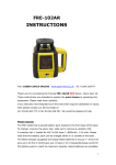
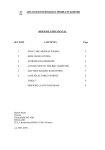
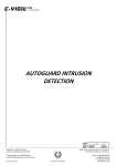
Self-leveling Rotary Laser Level
FRE-203 Green
P.R.Engineering Ltd – Chesterfield, UK. Tel +44 (0)1246 269 777
www.laser-level.co.uk
1. Overview
Our model FRE-203 Green output instruments are equipped with a high quality
1
semiconductor diode, which gives a high intensity laser beam. The laser output
can be set in both the horizontal and vertical (plumb) planes, as illustrated below:
When the instrument is set upright, its output is a laser beam giving a horizontal
scanning surface and a plumb-line, automatically. When the instrument is set-up
horizontally, it will give a plumb scanning surface and a vertical line.
The FRE-203 has an intense Green beam, not as shown.
cont….
2. Features
2.1 Main Body
2
Laser point
Laser window
Laser Module
Carry Handle
Control Panel
2.2 Control Panel
X-axis
Y-axis
Left scanning &
stepping
Scanning angle
Right scanning &
stepping
Speed
control
Mode: Automatic or Manual
Power ON/OFF
Automatic drift system
(Bump sensor)
2.3 Control Panel keypad
2.1.1. ON/OFF: Switches the instrument power ON and OFF.
3
2.1.2. Power Indicator: When illuminated red, the instrument is operational. Otherwise, it
is closing down.
2.1.3. Mode Indicator: No LED illuminated, the instrument is set for Automatic (self)
leveling. A green illuminated LED, leveling is Manual. A green flashing LED indicates
Manual alarm. The slope (grade) set is outside the range of the instrument.
2.1.4. Automatic drift system (Bump sensor): Warns the User of a misaligned device.
2.1.5. Automatic drift system LED: When the green indicator light flashes slowly, the
automatic drift mode is set. When the light flashes quickly, the laser level has detected a
bump & it stops rotating & gives no level output. Press again to restart.
2.1.6. Speed Control: 5 rotating speed settings 0, 60, 120, 300, 600 r.p.m.
2.1.7. Directional scanning: 5 scanning angle settings: 0, 10°, 45°, 90°, 180°
2.1.8. Manual / Automatic: Controls the Mode of leveling.
2.1.9. Left-scanning: In scan mode, this moves the scan line anti-clockwise.
2.1.10. Right-scanning: In scan mode, this moves the scan line clockwise.
2.1.11. X-axis : Adjusts the X-axis slope (grade), when the instrument is switched into
manual mode. (See direction of X marking on top of the instrument.)
2.1.12. Y-axis : Adjusts the Y-axis slope (grade), when the instrument is switched into
manual mode. (See direction of Y marking on top of the instrument.)
3.
Battery Installation:
A rechargeable battery pack is available for this instrument.
(Optional: 4 x type C dry cell pack)
3.1.1 Carefully invert the instrument & remove the 4 central base screws.
3.1.2 Withdraw the battery pack, noting the terminal position.
3.1.3 To replace the battery pack, reverse this procedure.
3.2. Positioning of Laser instrument:
3.2.1 for Horizontal scanning Mount the instrument on a tripod, on a stable flat surface, or support on a Wall Bracket.
This mounting surface must be within the range from -5° ~ +5° for correct operation.
If outside this range, then the instrument will NOT automatically (self) level.
4
3.2.2. for Vertical scanning Mount the instrument on a stable, flat surface and keep the slope of instrument within the
range -5° ~ +5° for correct operation.
3.3 OPERATION:
3.3.1 Power
Press the green ON button to power-up the instrument. Automatic leveling is set. When
the power indicator flashes red, it indicates low battery voltage. You need to recharge the
battery pack. Pressing the ON/OFF button again powers-down the instrument and the
indicator goes out.
3.3.2 Leveling
Switch the instrument ON - the laser beam flashes. After a period of time the system
automatically levels; then the laser module stops flashing & the head rotates at a speed of
600 r.p.m. If the instrument is positioned on a slope which exceeds the range -5° ~ +5°,
the laser output will continue to flash - as it is outside its auto-leveling range.
Note: In alarm condition, the instrument will automatically shut-down after five minutes, to
conserve power.
3.3.3. Rotating
3.3.3.1. Continuous laser rotation
Press the control panel button (marked with a hare & tortoise!) to adjust the rotational
speed in 5 incremental settings: 0, 60, 120, 300, 600 r.p.m.
3.3.3.2.
Stepping spinning
Set the rotating speed to 0 r.p.m, to STOP the laser dot. Press the right-stepping button to
move the dot in small increments, clockwise. Or press the left-stepping button to move
the laser dot, counter-clockwise.
3.3.4 Directional scanning
3.3.4.1. Press the Scanning Angle button: the laser dot will form a short line on the wall.
By pressing this button repeatedly, the line length will change depending on the set
scanning angle in 5 incremental settings: 0°, 10°, 45°, 90°, 180°.
3.3.4.2.
Press the left-scanning or the right-scanning buttons to change the position of
the scan line around the room to the area you are working.
5
3.3.5 Slope (Grade) adjustment
When the instrument is set upright for horizontal scanning, the slope of both the X-axis
and Y-axis can be adjusted. Press the Automatic/Manual Mode button, to illuminate the
green LED - which indicates the instrument is set to Manual leveling.
3.3.5.1. Slope of X-axis
a. Aim the X1-beam in the direction of the slope required, as depicted below :
b. Press the button
or
to move the laser beam up or down.
3.3.5.2. Slope of Y-axis
a. Aim the Y1-beam in the direction of the slope required.
b. Press the key
or
to move the laser beam up or down.
Note: By pressing the Automatic/Manual Mode button again, the green indicator LED
goes out & the instrument resets itself to Automatic leveling. This takes a few seconds.
4. Power Connection
Charger
Plug
Indicator light
When
the
Small socketred
ON/OFF indicator flashes, the batteries need
to be charged-up as soon as possible. Connect the charger to a suitable Mains supply
6
and insert the small plug into the socket at the bottom of the instrument’s control panel (as
shown above).
The LED on the charger will change from flashing red to continuous red – to indicate that
the batteries are accepting a charge.
Then, when the indicator light on the charger flashes again, it shows that recharging is
complete. Please be aware that 4 to 5 charge / discharge cycles are required to bring new
batteries up to full capacity.
Important Notes:
(1) When using the standard rechargeable batteries supplied, a full recharge will take
around 7 hours.
(2) Power required for the Charger : Frequency 50~60HZ, Voltage 85~265V
(3) You can both use & charge the instrument, simultaneously.
(4) When storing the instrument (or leaving the instrument unused for a long time),
the batteries (either rechargeable or dry cell) must be removed to prevent
damage to the equipment.
(5) Brand-new rechargeable batteries or long-time, unused rechargeable batteries
need to be recharged and discharged 4/5 times to attain their full capacity.
5. Remote control
The Remote Control uses infrared to signal to the laser instrument.
Aim the RC-10 directly at the instrument for the best results.
Available range is approx: 30m indoors & 20m outdoors.
The keypad has 9 buttons; & a top red LED, which indicates an output every time any of
the buttons are selected.
The functions are as follows :
(1) Rotating/Spinning: Operating method referring to 3.3.3
(2) Directional scanning : Operating method referring to 3.3.4
(3) Slope (grade) adjustment : Operating method referring to 3.3.5
6. Accuracy checking
7
6.1. Horizontal surface checking
6.1.1. Place the instrument at a point approx. 50m from a wall (or set a scale-plate 50m
away from the instrument), and then adjust the level of the base approximately to aim the
X1 to the wall (or scale-plate), as depicted bellow :
Approximately 50m
6.1.2. After switching on the power, use the laser detector measuring the h1 of X1-beam
on the wall or scale-plate.
6.1.3. Loosen the screw of the tripod and then turn around the instrument through 180°
to measure the h2 of X2-beam on the wall or scale-plate.
D value between h1 and h2 to be less than 10mm.
6.1.4. Check the Y-beam in the same way.
6.2 Horizontal line checking
6.2.1. Place the instrument between two walls at a distance of about 30m (or two
scale-plates at a distance of about 30m).
6.2.2. Place the instrument to a horizontal setting and then adjust the instrument.
6.2.3. Switch ON the power and then measure the middle point of the laser beam on the
wall (or scale-plate) : hA, hB and hA’, hB’
6.2.4. ∆1=hA-hA’, ∆2=hB-hB’
8
D-value between ∆1 and ∆2 ought to be less than 6mm.
7. Specifications
Model
RL-100(Red beam)
FRE-203 Green / RL-100G(Green)
Working range
Radius 60m
Diameter 1,000m (with detector)
Radius 100m
Diameter 1,400m (with detector)
Leveling range
Auto drift system
Accuracy
Spinning speed
Scanning angle
Slope adjusting
(grade) range
Temperature
Continuous
Working (hrs)
Water-proof rating
Size
Weight
±5°
Yes
±10”
0, 60, 120, 300, 600 rpm
0°, 10°, 45°, 90°, 180°
±5°
–20°C ~ +50°C
20 hours
7 hours
IP 54
160(L) x 160(W) x 185(H) mm
2.0kg (including batteries)
8. Standard kit comprises of:
Carry case, laser level instrument, remote control, laser detector
(receiver) with clamp bracket
Re-chargeable batteries, mains charger & user manual
9