1
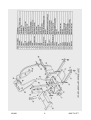
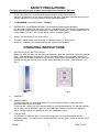
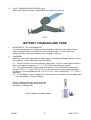
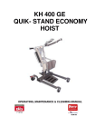
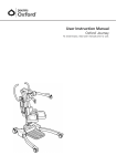
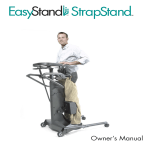
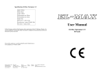
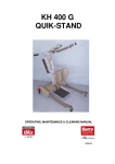
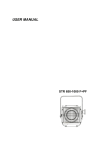
KH 401
MULTI-LIFT
OPERATING, MAINTENANCE & CLEANING MANUAL
KEIM - 011
INDEX
PAGE
SPECIFICATIONS
2
SPARE PART
3
SAFETY PRECAUTIONS
4
OPERATING INSTRUCTIONS
4
BATTERY CARE AND CHARGING
5
MAINTENANCE INSTRUCTIONS
6
ASSEMBLY/DISASSEMBLY
8
CLEANING INSTRUCTIONS
8
SPECIFICATIONS
DIMENSIONS:
Length
Width
Height
Effective lift range
Leg gating (inside)
Lift reach
Base height
Leg height from floor
Turning radius
LIFT SPEED:
Slow - 38mm per second
Fast - 58mm per second
LIFT DRY WEIGHT:
REMOVABLE BOOM:
REMOVABLE KNEEPAD:
42 Kg (with battery)
4.75Kg
4.40Kg
LIFT CAPACITY:
Max load - 150kg’s
CASTORS:
Ø150 Total lock rear polyurethane castor
Ø100 Swivel front polyurethane castor
Note: Smaller castors available on request.
FINISH:
Epoxy powder coated
Polyurethane legs and yoke
PVC cover, and upholstery kneepad
ELECTRICAL ITEMS:
KH401
1100mm
670mm
1220mm
430mm – 1700mm
510mm – 885mm
700mm
210mm
160mm
1300mm
Tested by Linak Australia to standards:AS 3108-1990
AS 3200.1-1990
2
MULTI-LIFT
KH401
3
MULTI-LIFT
SAFETY PRECAUTIONS.
For safety precautions only properly trained personal should use the hoist.
1.
The KH 401 Multi-lift is manufactured and tested with safety and function for
the carer and patients as the utmost importance. No parts should be removed from the hoist
without approval as this may create an unsafe working condition.
2.
The MAXIMUM safe working load is 150 Kg’s.
3.
EMERGENCY LOWERING/RAISING: The emergency lowering/raising buttons
can be used to lower/raise the hoist if there is a handset failure. The switches are located on
the controller under the big red emergency stop switch. Simply press using a ballpoint pen or
similar object, DO NOT use a sharp object such as a compass point.
4.
Always use the correct slings on the hoist.
5.
The hoist should not be used on rough or sloping surfaces. ie. Wheel chair
ramps etc, and does not recommend that the hoist be used outdoors.
OPERATING INSTRUCTIONS
1.
INSTALLATION OF BATTERY PACK.
Before the Multi-Lift Hoist can be operated the battery pack will need to be placed on charge
(See - Charging Battery Instructions). When the battery pack is fully charged, remove the
battery from the charger and place it on the hoist. Simply locate the battery on the mounting
bracket and clip the release lever into the secure position. The Hoist is now ready for use.
(fig 1)
Fig 1.
Fig 2.
2.
HANDSET:
2.1
RAISE/LOWER:
The Hoist operates via a hand controller. To raise or lower the hoist, simply press the
required switch on the touch pad.
There are four switches on the hand controller for raising and lowering. The top two switches
are for slow normal operation (tortoise); the middle two switches are for faster operation
(hare). Simply choose the speed that suits your application. (fig 2)
3.
LEG GATING:
To OPEN or CLOSE the “Gate” on the legs, simply press the hand controller with the
required function. (The lower set of switches operates the leg “gate”). Open on the left, close
on the right.
KH401
4
MULTI-LIFT
4.
YOKE - SLING MOUNTING POINTS (fig 3)
Refer to the fitting instructions supplied with your chosen sling.(fig 15)
Fig 3.
BATTERY CHARGING AND CARE
1.
MOUNTING OF THE CHARGING UNIT
It is recommended that the charging unit be mounted on a wall out of the way of normal
traffic, at approximately waist high, close to an electrical outlet. This will help in easy
attachment and removal of the battery when charging is required.
2.
CHARGING
Before the Hoist can be operated the battery pack will need to be charged. Minimum 4 hours
for flat battery. Please follow the instructions below.
2.1 Plug the charger unit into the 240-Volt supply outlet. The unit is now ready to accept a
battery that requires charging; a GREEN L.E.D. (ON) will be displayed. (fig 10)
2.2 To charge the battery, simply locate the battery on the mount bracket and clip into
position. (The GREEN and ORANGE L.E.D. on the front of the charger will be displayed).
The battery is fully charged when the ORANGE L.E.D. is OFF and only the GREEN L.E.D. is
displayed.
2.3 If a two-battery system is going to be used, replace the first battery once charged, with
the second battery. Charge as above.
NOTE: A battery pack may remain on charge
indefinitely without any detrimental effects to
the battery or charging unit.
Fig 10 Charger unit without battery.
KH401
5
MULTI-LIFT
3.
BATTERY CARE
The batteries are fully sealed lead acid batteries, which should be recharged on a regular
basis. To care for your batteries and obtain the maximum life DO NOT allow the batteries to
run totally flat before recharging.
The controller is fitted with an audio low battery warning alarm. When this warning alarm
sounds complete the lift process, then change the battery and recharge. Kerry Equipment
recommends that a 2-battery system be used; this allows one battery to always be on charge
while the other is in use, and hence the hoist may never be out of service with a flat battery.
MAINTENANCE INSTRUCTIONS
LUBRICATION
The Hoist requires periodical lubrication. These points are:
1.
CASTORS
It is always best practice to remove all hair and lint from the castors as soon as possible,
always allowing free movement of all the wheels.
The head bearing will need lubricating monthly. Simply spray TAC-2 up into the bearing
while rotating the castor.(fig 11)
The wheel also requires lubricating every month. To do this the wheel must be unbolted and
removed from the castor frame. TAC-2 can then be sprayed into the hub centre to lubricate
the internal bearings. (fig 12)
Fig 11.
2.
Fig 12.
BASE PIVOT POINTS
All pivot points will need to be lubricated monthly with TAC-2 or similar lubricant.
Simply spray the recommended points for 2 seconds on either side.
The hoist has to be turned onto its side for access to the following lubrication points. (To do
this 2 people are required.)
Follow the instruction below:
2.1 Both people are to stand on one side of the hoist. One near the push handle, the other
by the side of the hoist.
2.2 The person near the push handle locks the total lock castors.
2.3 In conjunction with one another pull the hoist towards the side, lowering the hoist onto
the floor.
You now have access to all the lubrication points under the base. ie: pivot points, leg lever
and leg pivot. Simply spray TAC-2 on all the pivot points for 2 seconds.
KH401
6
MULTI-LIFT
3.
Leg Actuator Pivots (fig 13)
Leg Pivots
Tie Rod Pivot Points
Fig 13.
4.
ARM, ACTUATOR and SPRING PIN LUBRICATION POINTS
The arm pivot points will need to be lubricated monthly with TAC-2 or similar lubricant (fig
14.). Simply spray on each side of the recommended points as required. The boom
removable socket and spring button/pin will also need lubricating as required.
4.1
Arm Pivot
Boom Socket/Pin
Actuator Pivots
Arm pivot
Boom spring button/pin
Actuator pivot
Lower Actuator pivot
Fig 14.
TAC-2 is a CRC product and is available from most automotive outlets or from Kerry Equipment.
KH401
7
MULTI-LIFT
ASSEMBLY / DISASSEMBLY INSTRUCTIONS
Kerry Equipment fully assembles their hoist prior to delivery. Kerry Equipment only recommends
qualified service personal to work or service any of their hoists. Any assembly or disassembly
should be checked with Kerry Equipment and or Distributor before commencing with any repair.
GENERAL CLEANING
1.
The hoist can be cleaned with a low strength detergent, warm water and a soft textured
cloth. This includes all Epoxy powder coated framework, PVC cover, polyurethane legs, kneepad
and yoke.
2.
CAUTION
Do not immerse any parts in water.
Do not allow water/cleaning liquid to enter the battery or controller.
Clean up spills immediately.
3.
SLING CARE
Protect from direct sunlight.
Repair any cuts or fraying immediately.
Slings are machine washable.
Please refer to care instructions on the sling.
Supplied by:
KH401
8
MULTI-LIFT