1
Cat. No. Z200-E1-02
G3ZA
Multi-channel
Power Controller
USER’S MANUAL
G3ZA
Multi-channel Power Controller
User’s Manual
Produced February 2007
iv
Preface
OMRON products are manufactured for use according to proper procedures
by a qualified operator and only for the purposes described in this manual.
This manual describes the functions, performance, and application methods
needed for optimum use of the G3ZA.
Please observe the following items when using the G3ZA.
• This product is designed for use by qualified personnel with a knowledge
of electrical systems.
• Read this manual carefully and make sure you understand it well to
ensure that you are using the G3ZA correctly.
• Keep this manual in a safe location so that it is available for reference
when required.
OMRON, 2004
All rights reserved. No part of this publication may be reproduced, stored in a retrieval system, or transmitted, in any form, or
by any means, mechanical, electronic, photocopying, recording, or otherwise, without the prior written permission of
OMRON.
No patent liability is assumed with respect to the use of the information contained herein. Moreover, because OMRON is constantly striving to improve its high-quality products, the information contained in this manual is subject to change without
notice. Every precaution has been taken in the preparation of this manual. Nevertheless, OMRON assumes no responsibility
for errors or omissions. Neither is any liability assumed for damages resulting from the use of the information contained in
this publication.
v
Read and Understand this Manual
Please read and understand this manual before using the product. Please consult your OMRON
representative if you have any questions or comments.
Warranty and Limitations of Liability
WARRANTY
OMRON's exclusive warranty is that the products are free from defects in materials and workmanship for a
period of one year (or other period if specified) from date of sale by OMRON.
OMRON MAKES NO WARRANTY OR REPRESENTATION, EXPRESS OR IMPLIED, REGARDING NONINFRINGEMENT, MERCHANTABILITY, OR FITNESS FOR PARTICULAR PURPOSE OF THE PRODUCTS.
ANY BUYER OR USER ACKNOWLEDGES THAT THE BUYER OR USER ALONE HAS DETERMINED
THAT THE PRODUCTS WILL SUITABLY MEET THE REQUIREMENTS OF THEIR INTENDED USE.
OMRON DISCLAIMS ALL OTHER WARRANTIES, EXPRESS OR IMPLIED.
LIMITATIONS OF LIABILITY
OMRON SHALL NOT BE RESPONSIBLE FOR SPECIAL, INDIRECT, OR CONSEQUENTIAL DAMAGES,
LOSS OF PROFITS OR COMMERCIAL LOSS IN ANY WAY CONNECTED WITH THE PRODUCTS,
WHETHER SUCH CLAIM IS BASED ON CONTRACT, WARRANTY, NEGLIGENCE, OR STRICT
LIABILITY.
In no event shall the responsibility of OMRON for any act exceed the individual price of the product on which
liability is asserted.
IN NO EVENT SHALL OMRON BE RESPONSIBLE FOR WARRANTY, REPAIR, OR OTHER CLAIMS
REGARDING THE PRODUCTS UNLESS OMRON'S ANALYSIS CONFIRMS THAT THE PRODUCTS
WERE PROPERLY HANDLED, STORED, INSTALLED, AND MAINTAINED AND NOT SUBJECT TO
CONTAMINATION, ABUSE, MISUSE, OR INAPPROPRIATE MODIFICATION OR REPAIR.
Application Considerations
SUITABILITY FOR USE
OMRON shall not be responsible for conformity with any standards, codes, or regulations that apply to the
combination of products in the customer's application or use of the products.
At the customer's request, OMRON will provide applicable third party certification documents identifying
ratings and limitations of use that apply to the products. This information by itself is not sufficient for a
complete determination of the suitability of the products in combination with the end product, machine,
system, or other application or use.
The following are some examples of applications for which particular attention must be given. This is not
intended to be an exhaustive list of all possible uses of the products, nor is it intended to imply that the uses
listed may be suitable for the products.
• Outdoor use, uses involving potential chemical contamination or electrical interference, or conditions or
uses not described in this manual.
• Nuclear energy control systems, combustion systems, railroad systems, aviation systems, medical
equipment, amusement machines, vehicles, safety equipment, and installations subject to separate
industry or government regulations.
• Systems, machines, and equipment that could present a risk to life or property.
Please know and observe all prohibitions of use applicable to the products.
NEVER USE THE PRODUCTS FOR AN APPLICATION INVOLVING SERIOUS RISK TO LIFE OR
PROPERTY WITHOUT ENSURING THAT THE SYSTEM AS A WHOLE HAS BEEN DESIGNED TO
ADDRESS THE RISKS, AND THAT THE OMRON PRODUCTS ARE PROPERLY RATED AND INSTALLED
FOR THE INTENDED USE WITHIN THE OVERALL EQUIPMENT OR SYSTEM.
PROGRAMMABLE PRODUCTS
OMRON shall not be responsible for the user's programming of a programmable product, or any
consequence thereof.
vi
Disclaimers
CHANGE IN SPECIFICATIONS
Product specifications and accessories may be changed at any time based on improvements and other
reasons.
It is our practice to change model numbers when published ratings or features are changed, or when
significant construction changes are made. However, some specifications of the products may be changed
without any notice. When in doubt, special model numbers may be assigned to fix or establish key
specifications for your application on your request. Please consult with your OMRON representative at any
time to confirm actual specifications of purchased products.
DIMENSIONS AND WEIGHTS
Dimensions and weights are nominal and are not to be used for manufacturing purposes, even when
tolerances are shown.
PERFORMANCE DATA
Performance data given in this manual is provided as a guide for the user in determining suitability and does
not constitute a warranty. It may represent the result of OMRON's test conditions, and the users must
correlate it to actual application requirements. Actual performance is subject to the OMRON Warranty and
Limitations of Liability.
ERRORS AND OMISSIONS
The information in this document has been carefully checked and is believed to be accurate; however, no
responsibility is assumed for clerical, typographical, or proofreading errors, or omissions.
vii
Safety Precautions
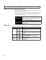
■ Definition of Precautionary Information
The following notation is used in this manual to provide precautions required
to ensure safe usage of the product.
The safety precautions that are provided are extremely important to safety.
Always read and heed the information provided in all safety precautions.
The following notation is used.
WARNING
Indicates a potentially hazardous situation which, if not
avoided, will result in minor or moderate injury, or may
result in serious injury or death. Additionally there may
be significant property damage.
CAUTION
Indicates a potentially hazardous situation which, if not
avoided, may result in minor or moderate injury or in
property damage.
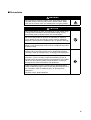
■ Symbols
Symbol
Meaning
General Caution
Indicates non-specific general cautions, warnings,
and dangers.
Caution
Electrical Shock Caution
Indicates possibility of electric shock under specific
conditions.
viii
Prohibition
General Prohibition
Indicates non-specific general prohibitions.
Mandatory
Caution
General Caution
Indicates non-specific general cautions, warnings,
and dangers.
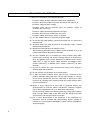
■ Precautions
WARNING
Do not touch the terminals and the wires while power is being
supplied. Doing so may possibly result in electric shock. Make
sure that the terminal cover is installed before using the product.
CAUTION
Do not allow pieces of metal, wire clippings, or fine metallic chips
or filings from installation to enter the product. Doing so may
occasionally result in electric shock, fire, or malfunction.
Do not use the product in locations of flammable or explosive
gases. Doing so may occasionally result in minor or moderate
explosion, causing minor or moderate injury, or property damage.
Do not attempt to disassemble, repair, or modify the product.
Doing so may occasionally result in minor or moderate injury due
to electric shock.
Perform correct setting of the product according to the application.
Failure to do so may occasionally cause unexpected operation,
resulting in minor or moderate injury, or damage to the equipment.
Ensure safety in the event of product failure by taking safety
measures, such as installing a separate monitoring system to
provide alarms for preventing excessive temperature rise. Product
failure may occasionally prevent control operation, resulting in
damage to the connected facilities and equipment.
Tighten the terminal screws securely using a tightening torque
within the following ranges. Loose screws may occasionally cause
fire, resulting in minor or moderate injury, or damage to the
equipment.
Terminal screws: 0.40 to 0.56 N·m
ix
Precautions for Safe Use
(1) Do not use the product in the following locations.
• Locations subject to direct radiant heat from heating equipment
• Locations where the product may come into contact with water or oil
• Locations subject to direct sunlight
• Locations where dust or corrosive gases (in particular, sulfuric or
ammonia gas) are present
• Locations subject to extreme temperature changes
• Locations where icing or condensation may occur
• Locations subject to excessive shocks or vibration
(2) Use this product within the rated load and power supply.
(3) Ensure that the rated voltage is achieved no longer than 2 s after turning
the power ON.
(4) Use/store within the rated temperature and humidity ranges. Provide
forced-cooling if required.
(5) Minimum mounting distance of G3ZA is 10 mm.
When mounting the G3ZA near the SSRs, mount the G3ZA so as to not
interfere with the heat dissipation of the SSR.
(6) Use the specified size of insulated type crimp terminals (M3, width:
5.8 mm max.) for wiring and attach insulative sleeves. To connect bare
wires, use AWG22 (cross section: 0.326 mm2) to AWG14 (cross section:
2.081 mm2) to wire the power supply terminals and AWG22 (cross
section: 0.326 mm2) to AWG16 (cross section: 1.039 mm2) for other
terminals.
(7) Be sure to confirm the correct terminal and polarity when wiring the
terminal block and connectors.
(8) Do not connect any conductors to unused terminals.
(9) In order to prevent inductive noise, wire the lines connected to the
product separately from power lines carrying high voltages or currents.
Do not wire in parallel with or in the same cable as power lines. Other
measures for reducing noise include running lines along separate ducts
and using shield lines.
(10) Attach a surge suppressor or noise filter to peripheral devices that
generate noise (in particular, motors, transformers, solenoids, magnetic
coils or other equipment that have an inductance component).
Do not install the product near devices generating strong high-frequency
fields or surges. When using a noise filter, check the voltage and current
and install it as close to the product as possible.
(11) For a safety disconnection of the power-line in the application the
equipment shall be provided with disconnecting devices suitable for
isolation (e.g. circuit breakers IEC60947-2, power switches IEC60947-3,
and power plugs).
x
Precautions when Using Unit Version 1.0
Unit version 1.0 is for use with single-phase loads only. Connect single-phase
zero-cross SSRs. Do not connect three-phase SSRs, electromagnetic relays,
or single-phase SSRs without the zero-cross function.
Precautions when Using Unit Version 2.0
• When wiring the SSR, check the G3ZA's settings and select the correct
SSR from the following supported SSRs.
• SSR for single-phase heater with zero-cross function
• SSR for single-phase heater without zero-cross function
• SSR for three-phase heater
Do not connect an electromagnetic relay.
• When wiring the CT, check the G3ZA's settings and select the correct CT
from the following supported CTs.
• E54-CT1
• E54-CT3
• G3ZA-CT150L
Note For details on checking the G3ZA's unit version, refer to Identifying an
Upgraded Controller on page xiii.
xi
Conventions Used in This Manual
■ Meanings of Abbreviations
The following abbreviations are used in parameter names, figures, and in text
in this manual. These abbreviations mean the following:
Abbreviation
xii
Term
ch
MV
Channel
Manipulated variable
EJ1
EJ1-series Temperature Controller (See note.)
Note The EJ1 Series is a series of OMRON Temperature Controllers. For details on the functions of
these Temperature Controllers, refer to the EJ1
Modular Temperature Controller User's Manual
(Cat. No. H142) or the EJ1G Modular Temperature Controllers for Gradient Temperature Control
User's Manual (Cat. No. H143).
■ Functional Upgrades in G3ZA Version 2.0
Functions were added to control halogen heaters and three-phase heaters.
Descriptions of these functional upgrades have been added to this manual
and are indicated by the V 2 symbol.
Identifying an Upgraded Controller
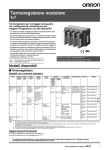
The Controller's version can be identified on the Unit's label or the box label. If
there is no unit version number, the Controller's version is 1.0.
Box Label
Version
G3ZA-4H403-FLK-UTU
TYPE
SOLID STATE RELAY
VOLTS
AC100-240V
LOT
No.
Ver. 2.0
QTY
****
1
1
Power Controller Label
Version
xiii
xiv
TABLE OF CONTENTS
SECTION 1
Overview . . . . . . . . . . . . . . . . . . . . . . . . . . . . . . . . . . . . . . . . .
1-1
1
Features . . . . . . . . . . . . . . . . . . . . . . . . . . . . . . . . . . . . . . . . . . . . . . . . . . . . . . . . . . . . . . . . .
2
SECTION 2
Preparations . . . . . . . . . . . . . . . . . . . . . . . . . . . . . . . . . . . . . .
7
2-1
Installation . . . . . . . . . . . . . . . . . . . . . . . . . . . . . . . . . . . . . . . . . . . . . . . . . . . . . . . . . . . . . . .
8
2-2
How To Use the Terminals . . . . . . . . . . . . . . . . . . . . . . . . . . . . . . . . . . . . . . . . . . . . . . . . . .
11
SECTION 3
Communications (CompoWay/F) . . . . . . . . . . . . . . . . . . . . .
17
3-1
Communications Settings . . . . . . . . . . . . . . . . . . . . . . . . . . . . . . . . . . . . . . . . . . . . . . . . . . .
18
3-2
Frame Configuration . . . . . . . . . . . . . . . . . . . . . . . . . . . . . . . . . . . . . . . . . . . . . . . . . . . . . . .
19
3-3
FINS-mini Text . . . . . . . . . . . . . . . . . . . . . . . . . . . . . . . . . . . . . . . . . . . . . . . . . . . . . . . . . . .
21
3-4
Variable Area Write . . . . . . . . . . . . . . . . . . . . . . . . . . . . . . . . . . . . . . . . . . . . . . . . . . . . . . . .
23
3-5
Variable Area Read . . . . . . . . . . . . . . . . . . . . . . . . . . . . . . . . . . . . . . . . . . . . . . . . . . . . . . . .
24
3-6
Operation Command . . . . . . . . . . . . . . . . . . . . . . . . . . . . . . . . . . . . . . . . . . . . . . . . . . . . . . .
25
3-7
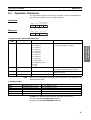
Controller Attribute Read . . . . . . . . . . . . . . . . . . . . . . . . . . . . . . . . . . . . . . . . . . . . . . . . . . .
26
3-8
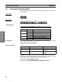
Controller Status Read. . . . . . . . . . . . . . . . . . . . . . . . . . . . . . . . . . . . . . . . . . . . . . . . . . . . . .
27
3-9
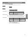
Echo-back Test. . . . . . . . . . . . . . . . . . . . . . . . . . . . . . . . . . . . . . . . . . . . . . . . . . . . . . . . . . . .
28
SECTION 4
Functions . . . . . . . . . . . . . . . . . . . . . . . . . . . . . . . . . . . . . . . . .
29
4-1
Setup Procedure . . . . . . . . . . . . . . . . . . . . . . . . . . . . . . . . . . . . . . . . . . . . . . . . . . . . . . . . . . .
30
4-2
Selecting the SSR (Control Method) 4 or 8-channel Models) . . . . . . . . . . . . . . . . . . . . . . .
31
4-3
Selecting the CT (4-channel Models Only) . . . . . . . . . . . . . . . . . . . . . . . . . . . . . . . . . . . . .
33
4-4
Allocating CTs (4-channel Models Only) . . . . . . . . . . . . . . . . . . . . . . . . . . . . . . . . . . . . . .
35
4-5
Detecting Heater Burnouts (4-channel Models Only) . . . . . . . . . . . . . . . . . . . . . . . . . . . . . .
36
4-6
Detecting Heater Overcurrent (4-channel Models Only) . . . . . . . . . . . . . . . . . . . . . . . . . . .
43
4-7
Detecting SSR Short-Circuits (4-channel Models Only). . . . . . . . . . . . . . . . . . . . . . . . . . . .
45
4-8
Detecting Communications Timeouts (4 and 8-channel Models) . . . . . . . . . . . . . . . . . . . . .
48
4-9
Setting the Soft Increase and Soft Decrease Times (4 and 8-channel Models) . . . . . . . . . .
49
4-10 Changing the Manipulated Variable (4 and 8-channel Models) . . . . . . . . . . . . . . . . . . . . . .
50
4-11 Offsetting the Control Output's ON Timing (4 and 8-channel Models) . . . . . . . . . . . . . . . .
51
4-12 Turning OFF a Control Output (4 and 8-channel Models) . . . . . . . . . . . . . . . . . . . . . . . . . .
52
4-13 Setting the Abnormal Current Detection Delay (4 and 8-channel Models) . . . . . . . . . . . . .
52
4-14 Setting Operation at Error (4 and 8-channel Models) . . . . . . . . . . . . . . . . . . . . . . . . . . . . . .
53
4-15 Monitoring the Effective Current . . . . . . . . . . . . . . . . . . . . . . . . . . . . . . . . . . . . . . . . . . . . .
54
SECTION 5
Troubleshooting . . . . . . . . . . . . . . . . . . . . . . . . . . . . . . . . . . .
57
5-1
Errors . . . . . . . . . . . . . . . . . . . . . . . . . . . . . . . . . . . . . . . . . . . . . . . . . . . . . . . . . . . . . . . . . . .
58
5-2
Handling Problems . . . . . . . . . . . . . . . . . . . . . . . . . . . . . . . . . . . . . . . . . . . . . . . . . . . . . . . .
59
xv
xvi
Appendix . . . . . . . . . . . . . . . . . . . . . . . . . . . . . . . . . . . . . . . . .
61
Index. . . . . . . . . . . . . . . . . . . . . . . . . . . . . . . . . . . . . . . . . . . . .
75
Revision History . . . . . . . . . . . . . . . . . . . . . . . . . . . . . . . . . . .
77
About this Manual:
This manual describes the installation and operation of the G3ZA Multi-channel Power Controller and
includes the sections described below.
Please read this manual carefully and be sure you understand the information provided before
attempting to install or operate the G3ZA. Be sure to read the precautions provided at the beginning of
this manual.
The Preface provides precautions for using the G3ZA and information on using this manual.
Section 1 introduces the G3ZA and its features.
Section 2 describes preparations for using the G3ZA, including installation and wiring.
Section 3 descrides how to use the G3ZA Controller's communications functions, focusing on the
CompoWay/F communications commands.
Section 4 describes the functions of the G3ZA so that these functions can be used effectively according to the application.
Section 5 provides information on problems that may occur during operation and corrective measures.
The Appendix provides G3ZA specifications, tables of settings, and other information.
!WARNING Failure to read and understand the information provided in this manual may result in personal injury or death, damage to the product, or product failure. Please read each section
in its entirety and be sure you understand the information provided in the section and
related sections before attempting any of the procedures or operations given.
xvii
xviii
This section introduces the G3ZA and its features.
1-1
Features V2 . . . . . . . . . . . . . . . . . . . . . . . . . . . . . . . . . . . . . . . . . . . . . . . . .
2
1
Overview
SECTION 1
Overview
Section 1-1
Features
Features
Overview
1-1
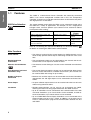
The G3ZA is a Multi-channel Power Controller with externally connected
SSRs. It can receive manipulated variables from a PLC, EJ1 Temperature
Controller, or other host via RS-485 communications and control heater power
with high precision via the SSRs.
SSR Drive Selection
V2
The control method used to drive the SSRs can be selected to enable using
the G3ZA for a variety of applications. For example, to use a single-phase
halogen heater, soft-start optimum cycle control can be selected to reduce
inrush power when starting.
SSR
Control method
SSR for single-phase heater with
Optimum cycle control
zero-cross function
SSR for single-phase heater without Soft-start optimum cycle
zero-cross function
control
SSR for three-phase heater with
zero-cross function
Application
example
Single-phase
heaters
Single-phase
halogen heaters
Three-phase optimum cycle Three-phase
control
heaters
Refer to 4-2 Selecting the SSR (Control Method) 4 or 8-channel Models) V2
for details on selecting the SSR and the control method.
Main Functions
Offset Control
• The timing of turning ON the control outputs for G3ZA channels can be
offset to help prevent control outputs from being turned ON at the same
time.
Manipulated Value
Calculations
• The manipulated variable can be calculated for one channel and the calculated value can be output for another channel.
Effective Current Monitor
• The effective current flowing to a heater can be monitored to one decimal
place.
V2
Error Detection (4-channel
Controllers Only)
• The current flowing through the heater can be monitored to detect heater
burnouts, heater overcurrents, and SSR short-circuits. (This function can
be used for SSRs with ratings of up to 150 A.)
Number of Outputs
Connected
• Between one and four outputs can be connected to 4-channel Controllers
and between one and eight outputs can be connected to 8-channel Controllers.
Alarm Output
• An open-collector output terminal can be used to inform the host of errors
without using communications.
Installation
• RS-485 communications can be used to set and operate the G3ZA,
reducing the amount of wiring required between the G3ZA and host.
• Up to 31 Controllers can be connected to one communications line. With
4-channel Controllers, up to 124 channels can be controlled, and with 8channel Controllers, up to 248 channels can be controlled.
• Up to 8 G3ZA Multi-channel Power Controllers can be connected to the
communications port of an EJ1@-TC2/4. In addition, it is not necessary to
create a communications program for communications between the EJ1
and G3ZA.
2
Setting an Abnormal
Current Detection Delay
V2
Available Models
• An abnormal current detection delay can prevent noise from causing false
detection by requiring a fixed number of consecutive error detections
(heater burnout, heater overcurrent, or SSR short-circuit detections)
before an error is actually detected.
The following four models are available.
Model number
Number of
channels
G3ZA-4H203-FLK-UTU 4 channels
G3ZA-4H403-FLK-UTU
G3ZA-8A203-FLK-UTU 8 channels
Error detection
Load power supply
Supported
100 to 240 V
Not supported
400 to 480 V
100 to 240 V
G3ZA-8A403-FLK-UTU
400 to 480 V
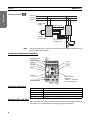
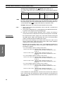
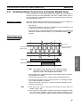
Connections
Single-phase SSRs
Phase R
Phase S
Phase T
Load power
supply
Trigger signal
SSR
G3ZA
SSR
......
Control
power supply
CT (4 channel
models only)
Note
Load
Load
Connect a power supply with the same phase as the SSRs to the load power
supply input terminals on the G3ZA.
3
Overview
Section 1-1
Features
Section 1-1
Overview
Features
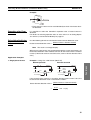
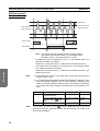
Three-phase SSRs
V2
Phase R
Phase S
Phase T
Load power
supply
SSR
Trigger signal
G3ZA
Control
power supply
CT (4 channel
models only)
Load
Note
Out of the three phases, connect any one phase to the G3ZA Controller's load
power supply input terminals.
Component Names and Functions
Terminal block
SW1
READY
SW2
SD/RD
OCC
READY
SD/RD
SW1
OCC
SW2
ERROR
ERROR
Terminal block
Alarm output
terminals
(G3ZA-@@403-FLKUTU models only)
Operation Indicators
Operation indicator
Meaning
READY
Lit while power is being supplied.
SD/RD
OCC
Lit while communicating with the host.
Lit while a control output is ON.
ERROR
Lights or flashes when an error is detected.
Switches SW1 and SW2
SW1 and SW2 are used to set the communications unit number and baud
rate. Refer to 3-1 Communications Settings on page 18 for details.
4
Section 1-1
Features
Outputs an alarm to the output terminal (open collector).
For details, refer to Alarm Output with 200 V Rating (Terminals 9 and 11) or
Alarm Output with 400 V Rating (Connector Pins A and B) on page 13.
Terminal Block
I/O signals connect to the terminal block. For details, refer to 2-2 How To Use
the Terminals on page 11.
5
Overview
Alarm Output
Overview
Features
6
Section 1-1
SECTION 2
Preparations
2-1
Installation. . . . . . . . . . . . . . . . . . . . . . . . . . . . . . . . . . . . . . . . . . . . . . . . . . . .
8
2-2
How To Use the Terminals . . . . . . . . . . . . . . . . . . . . . . . . . . . . . . . . . . . . . . .
11
Preparations
This section describes preparations for using the G3ZA, including installation and wiring.
7
Section 2-1
Installation
2-1
Installation
7×5=35
R
5.6 4 .5
84
43
63
9
76 max. (75 typical)
9
4.6 dia.
5.3
Preparations
91
Dimensions (Unit: mm)
R
35±0.3
45 max.
2.
111 max. (110 typical)
3
Mounting to DIN Rail
DIN Rail Products
When installing a DIN Rail inside a control panel, secure the DIN Rail with
screws in at least three locations.
• DIN Rail: PFP-50N (50 cm) or PFP-100N (100 cm)
• End Plates: PFP-M
8
Section 2-1
Installation
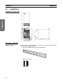
Mounting the G3ZA
Mount the G3ZA as shown in the diagram. First, pull down the DIN Track
mounting hook (1) and hook the top of the G3ZA on the DIN Track (2). Then
press the G3ZA onto the DIN Track far enough so that it can be locked in
place (3) and push the DIN Track mounting hook up to lock the G3ZA in place
(4).
(3)
(1)
Removing the G3ZA
(4)
Use a flat-blade screwdriver to pull down the DIN Track mounting hook (1) and
then pull out on the bottom of the G3ZA (2).
(2)
(1)
Mounting End Plates
Be sure to mount an End Plate on each side of the G3ZA so that it does not
slide on the DIN Track.
To mount an End Plate, hook the bottom of the End Plate on the bottom of the
DIN Track (1), place the top of the End Plate on the DIN Track (2), and then
pull down on the End Plate. Tighten the screw on the End Plate to secure it.
(2)
(1)
READY
SD/RD
SW 1
OCC
SW 2
ERROR
Note
Always mount one End Plate on each side of the G3ZA.
9
Preparations
(2)
Section 2-1
Installation
Mounting the G3ZA with Screws
Mounting Hole
Dimensions (Unit: mm)
Two, 4.2 dia. or M4 holes
Preparations
84 ±0.3
35 ±0.3
10
Section 2-2
How To Use the Terminals
How To Use the Terminals
+
19
Trigger output
12 V, 21 mA
Trigger
+
output
12 V,
21 mA
CH5
+
13
−
20
21
22
CH6
COM
CH7
Trigger output
12 V, 21 mA
+ Trigger
output
12 V,
21 mA
CH1
+
−
+
14
15
16
CH2
COM
CH3
Trigger output
12 V, 21 mA
+ Trigger
output
12 V,
21 mA
−
CT
CT
23
24
19
20
CH8
COM
CH1
CH2
Trigger output
12 V, 21 mA
+ Trigger
output
12 V,
21 mA
−
+
17
18
13
CH4
COM
CH1
CT
21
COM
Trigger output
12 V, 21 mA
Trigger
+ output
12 V,
21 mA
−
CT
22
23
24
CH3
CH4
COM
+
14
15
16
CH2
COM
CH3
Trigger output
−
12 V, 21 mA
Trigger
+ output
12 V,
21 mA
17
18
CH4
COM
Preparations
2-2
G3ZA-4H@03-FLK-UTU
G3ZA-8A@03-FLK-UTU
READY
SD/RD
SW 1
OCC
SW 2
ERROR
A
B
7
8
RS-485
+
9
7
11
8
RS-485
+
−
Alarm output
30 V, 50 mA
−
Alarm output
30 V, 50 mA
1
2
Control power supply
100 to 240 VAC
50/60 Hz
4
Load power supply
100 to 240 VAC
50/60 Hz
G3ZA-@@203-FLK-UTU
6
1
2
Control power supply
100 to 240 VAC
50/60 Hz
4
6
Load power supply
400 to 480 VAC
50/60 Hz
G3ZA-@@403-FLK-UTU
11
Section 2-2
How To Use the Terminals
Wiring Diagrams
Wiring Precautions
• To avoid the effects of noise, wire signal lines separately from power lines.
• Use cables with wires that have sufficient capacity.
• Attach solderless crimp terminals on wires that connect to the terminal
block.
• Use one of the following M3 solderless terminals for wiring.
Preparations
5.8 mm max.
5.8 mm max.
Use wires that are rated to withstand 70 °C minimum.
Control Power Supply
(Terminals 1 and 2)
In the wiring diagrams, the area within the lines indicating terminals numbers
is inside the G3ZA and the area outside the lines are outside the G3ZA.
• Connect terminals 1 and 2 as follows:
19 20 21 22 23 24
13 14 15 16 17 18
1
2
READY
SD/RD
OCC
ERROR
7 8 9
1 2
• The input power is 100 to 240 VAC.
11
4
6
Load Power Supply Input
(Terminals 4 and 6)
19 20 21 22 23 24
• To detect the zero-cross point of the load supply, connect the load power
supply to terminals 4 and 6 as follows:
4
6
13 14 15 16 17 18
READY
SD/RD
The voltage of the load power supply that can be connected depends on
the model of the Controller.
OCC
ERROR
100 to 240 VAC or 400 to 480 VAC
7 8 9
11
1 2
4 6
• The G3ZA detects the zero cross point of the load power supply.
• Use a load power supply with the same phase as the G3ZA Controller's
input power supply.
• The system will not be controlled correctly if the control power supply is
phase-controlled or has a different frequency from the input power supply.
RS-485 Communications
(Terminals 7 and 8)
19 20 21 22 23 24
• To communicate with a host system, connect the communications line to
terminals 7 and 8 as follows:
7
8
B
A
13 14 15 16 17 18
READY
(+)
SD/RD
(- )
RS-485
OCC
ERROR
7 8 9
1 2
12
• The connection type can be 1: 1 or 1: N. For 1: N connections, up to 32
Units can be connected, including the host.
11
4
6
• The maximum cable length is 500 m total.
Section 2-2
How To Use the Terminals
Cable Diagram (Reference)
• Use shielded twisted-pair cables (AWG16 to AWG22).
• Terminators must be connected at both ends of the transmission line,
including the PLC. Use terminators with a combined resistance of at least
54 Ω.
Alarm Output with 200 V
Rating (Terminals 9 and
11)
• Alarms are output on terminals 9 and 11.
9
11
SUB
19 20 21 22 23 24
13 14 15 16 17 18
READY
SD/RD
OCC
• The alarm output specifications are as follows:
Maximum load voltage: 30 VDC
Maximum load current: 50 mA
ERROR
7 8 9
1 2
11
4
6
Alarm Output with 400 V
Rating (Connector Pins A
and B)
• Alarms are output on pins A and B of the connector.
• The alarm output specifications are as follows:
A
19 20 21 22 23 24
13 14 15 16 17 18
Maximum load voltage: 30 VDC
Maximum load current: 50 mA
SUB
B
READY
SD/RD
OCC
ERROR
7 8 9
1 2
11
4
6
• The C-Grid SL connector for Molex Incorporated can be used for the connector.
Model number: 51030-0630
C-Grid SL Housing
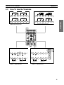
Trigger Outputs
(Terminals 13 to 18)
• The trigger outputs for channels 1 to 4 are output on terminals 13 to 18.
CH3
SSR
CH1
SSR
CH2
SSR
19 20 21 22 23 24
13
13 14 15 16 17 18
+
READY
14
CH4
SSR
15
+
12 VDC,
12 VDC, 21 mA
21 mA
−
16
+
17
18
−
+
12 VDC,
21 mA
12 VDC,
21 mA
SD/RD
OCC
Output voltage: 12 VDC ±15%
ERROR
7 8 9
1 2
PNP
11
4
6
Maximum load current: 21 mA
Short-circuit protection circuit provided.
13
Preparations
AWG22
Cross-sectional area of core:
0.326 mm2 min.
Section 2-2
How To Use the Terminals
Controllers without a Current Transformer Input Circuit (G3ZA-8A@03FLK-UTU)
• The trigger outputs for channels 5 to 8 are output on terminals 19 to 24.
CH5
SSR
CH7
SSR
CH8
SSR
CH6
SSR
19
+
20
21
−
+
22
+
Preparations
12 VDC,
12 VDC, 21 mA
21 mA
Current Transformer
Inputs (4-channel Models
Only, Terminals 19 to 24)
23
24
+
12 VDC,
21 mA
12 VDC,
21 mA
−
Controllers with Built-in Current Transformer Circuits (G3ZA-4H@03FLK-UTU)
• Connect terminals 19 to 24 to the current transformers (no polarity) to
detect heater burnouts, heater overcurrents, and SSR short-circuits.
19 20 21 22 23 24
CH1
CT
13 14 15 16 17 18
19
READY
SD/RD
CH3
CT
CH2
CT
20
21
CH4
CT
22
23
24
OCC
ERROR
7 8 9
1 2
There are four current transformer inputs that can be used.
11
4
Use the E54-CT1, the E54-CT3, or the G3ZA-CT150L from OMRON as
the current transformer.
6
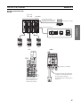
Connection Examples
Example Connection with
the PLC
Heater
Alarm output
20 mm min. (See note.)
RS-232C/485
Power Controller
power supply
CS/CJ-series PLC
Load power supply
(for zero-cross detection)
SSR
Note When installing next to an SSR,
provide sufficient spacing.
Example: When a current of 10 A (100%
of the control capacity) flows in
a G3PA-210B-VD SSR, a minimum spacing of 20 mm is
required between the G3ZA
Controller and the SSR.
14
Section 2-2
How To Use the Terminals
Example Connection with
the EJ1
EJ1@-TC4
or
EJ1@-TC2
EJ1C-EDU
Port A (connector): USB
connection can be made using the
E58-CIFQ1 (order separately).
CX-Thermo for setting
Computer
PLC
G3ZA
G3ZA
PT
Preparations
Port B: RS-485 (CompoWay/F)
Computer
G3ZA
EJ1
CN1
G3ZA
READY
SD/RD
OCC
ERROR
Set SW2 to 3 (57.6 kbit/s).
Connect the black line with a white stripe
to terminal 7 on the G3ZA and the black
line with no stripe to terminal 8.
Connect the G3ZA
Connecting Cable to the
CN1 connector on the
bottom of the TC Unit.
EJ1C-CBLA050 (order separately) (cable
length: 5 m)
15
Preparations
How To Use the Terminals
16
Section 2-2
SECTION 3
Communications (CompoWay/F)
3-1
Communications Settings . . . . . . . . . . . . . . . . . . . . . . . . . . . . . . . . . . . . . . . .
18
3-2
Frame Configuration . . . . . . . . . . . . . . . . . . . . . . . . . . . . . . . . . . . . . . . . . . . .
19
3-3
FINS-mini Text . . . . . . . . . . . . . . . . . . . . . . . . . . . . . . . . . . . . . . . . . . . . . . . .
21
3-4
Variable Area Write . . . . . . . . . . . . . . . . . . . . . . . . . . . . . . . . . . . . . . . . . . . .
23
3-5
Variable Area Read . . . . . . . . . . . . . . . . . . . . . . . . . . . . . . . . . . . . . . . . . . . . .
24
3-6
Operation Command . . . . . . . . . . . . . . . . . . . . . . . . . . . . . . . . . . . . . . . . . . . .
25
3-7
Controller Attribute Read . . . . . . . . . . . . . . . . . . . . . . . . . . . . . . . . . . . . . . . .
26
3-8
Controller Status Read . . . . . . . . . . . . . . . . . . . . . . . . . . . . . . . . . . . . . . . . . .
27
3-9
Echo-back Test . . . . . . . . . . . . . . . . . . . . . . . . . . . . . . . . . . . . . . . . . . . . . . . .
28
Communications
(CompoWay/F)
This section describes application information, including settings, communications, and controlling operation.
17
Section 3-1
Communications Settings
3-1
Communications Settings
G3ZA settings and operation are performed using RS-485 communications.
The communications functions use the program created in the host computer.
Descriptions of communications in this manual are therefore written from the
viewpoint of the host computer. For example, references to reading and writing mean reading data from the G3ZA to the host computer and writing data
from the host computer to the G3ZA.
Communications
(CompoWay/F)
Communications
Specifications
Transmission path connections
Multipoint
Communications method
Sync method
RS-485
Stop-start sync
Baud rate
Transmission code
9.6, 19.2, 38.4 or 57.6 kbit/s
ASCII
Data length
Stop bits
7 or 8 bits
1 or 2 bits
Error detection
Flow control
Vertical parity: None, even, or odd
None
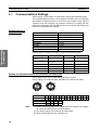
Communications settings are made as shown in the following table.
Setting
Setting range
Default
Setting method
Communications unit 0 to 31
number
1
SW1
Baud rate
9.6 kbit/s
SW2
Data length
9.6, 19.2, 38.4 or
57.6 kbit/s
7 or 8 bits
7 bits
Communications
Stop bits
Parity
1 or 2 bits
None, even, odd
2 bits
Even
Communications
Communications
Send standby time
0 to 99 ms
1 ms
Communications
Setting the Communications Unit Number and Baud Rate
The communications unit number and baud rate are set first.
These settings are made with SW1 and SW2 on the front of the G3ZA.
SW1
SW1
Unit number
SW2
Baud rate (kbit/s)
Note
SW2
0
1
2
3
4
5
6
7
8
9
A
0
9.6
C
D
E
F
1
2
3
19.2 38.4 57.6
(1) Refer to Connecting More Than 16 Controllers on page 64 in the Appendix when connecting more than 16 Controllers.
(2) The default settings are shaded in the above table.
(3) When connecting to the EJ1, set SW2 to 3.
18
B
00 01 02 03 04 05 06 07 08 09 10 11 12 13 14 15
Section 3-2
Frame Configuration
Other Communications Settings
Communications are used to set the data length, number of stop bits, parity,
and send standby time. To change the settings, use communications with the
default communications settings. Refer to 3-4 Variable Area Write on page 23
for the procedure for changing these settings.
Send Standby Time
The settings will be enabled only when the power is turned ON again or the
G3ZA is software reset.
The send standby time is used to adjust the time required for the host to
switch from sending to receiving status. For the G3ZA, this adjusts the time
between creating a response after receiving a transmission and switching to
send status.
Host
Receive status
Send status
Send
Receive
Receive
Send
Receive status
G3ZA
Send status
Response created
Send standby time
If switching time will not cause problems, the send standby time can be shortened to reduce the communications time with the host.
3-2
Frame Configuration
The communications protocol is the OMRON CompoWay/F protocol.
Commands from the host and responses from the G3ZA are sent in data
packets called frames. The structures of the command and response frames
are shown below.
In the following explanations, hexadecimal values are expressed by adding
the suffix H after the number, e.g., 02H. All other alphanumeric values in the
explanations indicate ASCII characters.
Command Frame
Format
Text
STX
Unit No.
02H
1
Sub-address S I D FINS-mini command text ETX
0
0
2
2
0
03H
1
1
BCC
1
BCC calculation range
Response Frames
Text
STX
Unit No.
02H
1
Sub-address
0
2
End code
FINS-mini command text
0
2
ETX BCC
03H
2
1
1
BCC calculation range
19
Communications
(CompoWay/F)
Note
Section 3-2
Frame Configuration
STX
This code indicates the beginning of the communications frame.
Always set 02H.
Unit. No.
• Set the unit number that is set on SW1 on the front of the G3ZA.
• No response will be received if another unit number is set.
Not used by the G3ZA. Always set to 0.
Sub-address and
SID
FINS-mini
command text
This text is the command. For details, refer to 3-6 Operation
Command on page 25.
ETX
This code indicates the end of the communications frame.
Always set to 03H.
BCC
This stores the result of the BCC calculation from the Unit No. to
EXT.
BCC Calculation Example
STX
Unit No.
02H 30H 30H
Sub-address SID
FINS-mini command text
30H 30H 30H 30H
35H 30H 30H 03H 36H
BCC = 30H 30H 30H 30H 30H 30H 35H
Communications
(CompoWay/F)
ETX BCC
30H 30H
03H = 36H
: XOR (exclusive OR) calculation
Note
No response will be returned unless the frame contains all elements up to the
ETX and BCC.
End Codes (CompoWay/F Communications)
End code
“0F”
“10”
Name
Description
Error detection priority
“11”
FINS command error The specified FINS command could not be executed.
Parity error
The OR of 1 bits in received data does not match the setting for the communications parity.
Framing error
Stop bit is “0”.
8
2
“12”
Overrun error
“13”
BCC error
“14”
Format error
“16”
“18”
Sub-address error
Frame length error
The sub-address is not included.
6
The received frame exceeds the required number of bytes. 4
“00”
Normal completion
Command processing was completed normally.
1
The next data was received when the reception data buffer 3
was full.
5
The calculated BCC value is different from the received
BCC value.
7
The FINS-mini command text contains characters other
than 0 to 9 and A to F. For details on the echoback test,
refer to 3-9 Echo-back Test on page 28.
SID and the FINS-mini command text are not included.
None
■ End Code Example
When the Sub-address, SID, and FINS-mini Command Text Are Not Included
• Command
STX
Unit No.
ETX
02H
0
03H
1
BCC
• Response
STX
Unit No.
02H
0
1
Subaddress
0
0
End code
1
6
ETX
BCC
03H
The sub-address is “00” and the end code is “16” (sub-address error).
20
Section 3-3
FINS-mini Text
3-3
FINS-mini Text
The FINS-mini command and response text is the text that form the command
and response communications.
The structure of FINS command and response text is shown below.
Command Text
An MRC (main request code) and SRC (sub-request code) followed by the
various required data is transferred in the command frame.
SID
Unit No.
Subaddress
STX
02H
Response Text
"00"
MRC
SRC
2
2
FINS-mini
BCC
command text ETX
"0"
03H
Data
Unit No.
STX
End code
Subaddress
02H
Communications
(CompoWay/F)
The MRES (main response code) and SRES (sub-response code) are transferred in the response frame following the above MRC/SRC. Data is then
transferred following the MRES and SRES.
ETX
FINS-mini
response text
BCC
"00"
03H
MRC
SRC
Response code
2
2
4
Data
Variable Type and Address
Note
Number of Elements
Refer to Parameter List on page 66.
The number of elements is expressed in 2-byte hexadecimal format.
The range for specifying the number of elements differs for each command.
Refer to 3-4 Variable Area Write or 3-5 Variable Area Read.
Communications Data
Setting (monitor) value
Hexadecimal
Communications data
(See note.)
Double word (8 digits)
Word
(4 digits)
Note
Negative values
2's complement
Decimal point
The decimal point is removed and the result is
converted to hexadecimal.
Example) 105.0 → 1050 → 0000041A (8 digits)
105.0 → 1050 → 041A
(4 digits)
Refer to Parameter List on page 66.
21
Section 3-3
FINS-mini Text
List of FINS-mini Service Commands
Communications
(CompoWay/F)
Note
22
MRC SRC
“01”
“02”
Service name
Variable Area Write
Description
Changes set values.
“01”
“30”
“01”
“05”
Variable Area Read
Operation Command
Reads set values.
Executes commands such as start/stop,
manipulated variable save and software
reset.
“05”
“06”
“03”
“01”
Controller Attribute Read Reads the model number of the Controller.
Controller Status Read
Reads the operating status.
“08”
“01”
Echo-back Test
Performs an echo-back test.
FINS is an acronym for Factory Interface Network Service. FINS is a protocol
used for message communications between controllers on OMRON FA networks.
Section 3-4
Variable Area Write
3-4
Variable Area Write
This command changes set values.
Command
Note
MRC
SRC Variable type
"01"
"02"
2
2
Write start
address
Bit position
Set values
No. of elements
"00"
2
4
2
4
No. of elements x 8 or 4
In the G3ZA, the bit position is not used. Set it to “00”.
Response
MRC
SRC
"01"
"02"
2
2
Response code
4
■ Variable Type and Write Start Address
Refer to the Parameter List on page 66 in the Appendix .
Specify the number of elements for which the set value is to be changed. Up
to 24 (0018H) elements can be specified.
Write data length
For double-word (8-digit) variable type
No. of elements
24 max. (0018H)
For word (4-digit) variable type
48 max. (0030H)
■ Response Code
Response code
“1002”
Error name
Command length too short
Cause
The command is too short.
“1101”
Area type error
The specified variable type
does not exist.
“1003”
Number of elements/Number
of data do not agree
“1100”
Parameter error
The specified number of elements does not agree with
the actual number of data elements.
The bit position specification
is not “00”.
A set value is outside of the
setting range.
“2203”
Operation error
An error occurred in nonvolatile memory.
“0000”
Normal end
Processing was completed
normally.
Example: The following command changes the manipulated variable for
channel 1 to 50% (set value: 8 digits).
Command: [STX]010000102C10000000001000001F4[ETX][BCC]
Response: [STX]01000001020000[ETX][BCC]
Example: The following command changes the manipulated variable for
channel 1 to 50% (set value: 4 digits).
Command: [STX]01000010281000000000101F4[ETX][BCC]
Response: [STX]01000001020000[ETX][BCC]
23
Communications
(CompoWay/F)
■ Number of Elements
Section 3-5
Variable Area Read
3-5
Variable Area Read
This command reads set values.
Command
Note
MRC
SRC
"01"
"01"
2
2
Bit
Variable
type Read start address position
No. of elements
"00"
2
2
4
4
In the G3ZA, the bit position is not used. Set it to “00”.
Response
MRC
SRC
"01"
"01"
2
2
Response code
4
Set values
No. of elements x 8 or 4
■ Variable Type and Read Start Address
Refer to the Parameter List on page 66 in the Appendix .
Communications
(CompoWay/F)
■ Number of Elements
Specify the number of elements for which the set value is to be read. Up to 25
(0019H) elements can be specified.
Read data length
For double-word (8-digit) variable type
No. of elements
25 max. (0019H)
For word (4-digit) variable type
50 max. (0032H)
■ Response Code
Response code
“1001”
Error name
Command length too long
Cause
The command is too long.
“1002”
“1101”
Command length too short
Area type error
“110B”
Response length too long
“1100”
Parameter error
“2203”
Operation error
“0000”
Normal end
The command is too short.
The specified variable type
does not exist.
The number of elements is
larger than the maximum
number allowed.
The bit position specification
is not “00”.
An error occurred in nonvolatile memory.
Processing was completed
normally.
Example: The following command reads the control variable for channel 1
(set value: 8 digits).
Command: [STX]010000101C00001000001[ETX][BCC]
Response: [STX]0100000101000000000000[ETX][BCC]
Example: The following command reads the control variable for channel 1
(set value: 4 digits).
Command: [STX]010000101800001000001[ETX][BCC]
Response: [STX]010000010100000000[ETX][BCC]
■ Precautions
• “0” is set when an address with no data set is read.
24
Section 3-6
Operation Command
3-6
Operation Command
This command is used to start and stop operation, save the manipulated variable, execute a software reset, or initialize settings.
Command
MRC
"30"
SRC
Operation Related
code information
"05"
2
2
MRC
SRC
"30"
"05"
2
2
2
2
Response
Response code
4
1. Operation Code and Related Information
“05”
Related information
Upper digit: Channel specification Refer to 4-12 Turning OFF a Control Output (4
and 8-channel Models) on page 52.
“0”: Channel 1
“1”: Channel 2
“2”: Channel 3
“3”: Channel 4
“4”: Channel 5
“5”: Channel 6
“6”: Channel 7
“7”: Channel 8
“F”: All channels
Lower digit: Start/stop
“0”: Start
“1”: Stop
“00”
“06”
Manipulated variable
save
Software reset
“0B”
Initialize settings
“00”
Note
Operation
“00”
Refer to 4-10 Changing the Manipulated Variable (4 and 8-channel Models) on page 50.
Performs the same processing as when the
G3ZA is turned ON.
Refer to 5-2 Handling Problems.
There is no response for a software reset. Responses are returned for all
other operation codes.
2. Response Codes
Response code
“1001”
Error name
Command length too long
The command is too long.
Cause
“1002”
“1100”
Command length too short
Parameter error
The command is too short.
The operation code or related information is not correct.
“2203”
“0000”
Operation error
Normal end
An error occurred in nonvolatile memory.
Processing was completed normally.
Example: The following command starts operation for channel 1.
Command: [STX]0100030050100[ETX][BCC]
Response: [STX]01000030050000[ETX][BCC]
25
Communications
(CompoWay/F)
Operation
Description
code
“01”
Start/stop
Section 3-7
Controller Attribute Read
3-7
Controller Attribute Read
This command reads the model number of the Controller and the communications buffer size.
Command
MRC
SRC
"05"
"03"
2
2
MRC
SRC
"05"
"03"
2
2
G
3
Response
Response code
Model number
"G3ZA-
Buffer size
"
"00D9"
10
4
4
1. Model Number
Z
Communications
(CompoWay/F)
Number
2. Buffer Size
A
–
1
Code
2
3
4
5
Meaning
A
“4”
“8”
4 channels
8 channels
B
“H”
“A”
With current transformer input
No current transformer input
C
“2”
“4”
Load power supply: 100 to 240 V
Load power supply: 400 to 480 V
DE
“03”
RS-485
The communications buffer size is expressed in 2-byte hexadecimal, and read
after being converted to 4-byte ASCII.
The buffer size is 217 bytes (D9H).
3. Response Code
Response code
Error name
“1001”
“2203”
Command length too long
Operation error
“0000”
Normal end
Cause
The command is too long.
An error occurred in nonvolatile memory.
Processing was completed
normally.
Example: The following command reads the model number and buffer size.
The response shows the Controller has four channels, supports a current
transformer, and has a load power supply of 400 to 480 V.
Command: [STX]010000503[ETX][BCC]
Response: [STX]01000005030000G3ZA-4H40300D9[ETX][BCC]
26
Section 3-8
Controller Status Read
3-8
Controller Status Read
This service reads the operating status and error status.
Command
MRC
SRC
"06"
"01"
2
2
MRC
SRC
"06"
"01"
2
2
Response
Response code
4
Operating Related
status information
2
2
1. Operating Status
Operating status
2. Related Information
The control output is ON for one or more channels.
The Controller is stopped or a zero cross error has
occurred during operation.
An OR of status bits 0 to 7 for all channels.
Refer to the Status in the Status Lists on page 65 in the Appendix .
Note
To read the status of individual channels, use the Variable Area Read command for the desired channel. Refer to 3-5 Variable Area Read for details.
3. Response Code
Response code
“1001”
Error name
Command length too long
Cause
The command is too long.
“2203”
Operation error
An error occurred in nonvolatile memory.
“0000”
Normal end
Processing was completed
normally.
Example:
Command: [STX]010000601[ETX][BCC]
Response: [STX]010000060100000100[ETX][BCC]
27
Communications
(CompoWay/F)
“00”
“01”
Meaning
Section 3-9
Echo-back Test
3-9
Echo-back Test
This command performs an echo-back test.
Command
MRC
SRC
"08"
"01"
2
2
Test Data
0 to 200
Response
1. Test Data
MRC
SRC
"08"
"01"
2
2
Response code
Test Data
4
0 to 200
The test data can contain up to 200 (00C8H) bytes.
Communications
(CompoWay/F)
Set the test data within the following ranges according to the communications
data length setting.
Data length
7 bits
Test data
ASCII 20H to 7EH
8 bits
ASCII 20H to 7EH or A1H to FEH
2. Response Codes
Response code
Error name
Cause
“1001”
“2203”
Command length too long
Operation error
The command is too long.
An error occurred in nonvolatile memory.
“0000”
Normal end
Processing was completed
normally.
Example:
Command: [STX]010000801123[ETX][BCC]
Response: [STX]01000008010000123[ETX][BCC]
28
SECTION 4
Functions
This section describes the functions of the G3ZA so that these functions can be used effectively according to the
application.
Setup Procedure . . . . . . . . . . . . . . . . . . . . . . . . . . . . . . . . . . . . . . . . . . . . . . .
Selecting the SSR (Control Method) 4 or 8-channel Models) V2 . . . . . . . .
30
33
4-4
Selecting the CT (4-channel Models Only) V2 . . . . . . . . . . . . . . . . . . . . . .
Allocating CTs (4-channel Models Only) V2 . . . . . . . . . . . . . . . . . . . . . . .
35
4-5
Detecting Heater Burnouts (4-channel Models Only) . . . . . . . . . . . . . . . . . .
36
4-2
4-3
31
4-6
Detecting Heater Overcurrent (4-channel Models Only) . . . . . . . . . . . . . . . .
43
4-7
Detecting SSR Short-Circuits (4-channel Models Only) . . . . . . . . . . . . . . . .
45
4-8
Detecting Communications Timeouts (4 and 8-channel Models). . . . . . . . . .
48
4-9
Setting the Soft Increase and Soft Decrease Times (4 and 8-channel Models) V2 49
4-10 Changing the Manipulated Variable (4 and 8-channel Models) . . . . . . . . . . .
50
4-11 Offsetting the Control Output's ON Timing (4 and 8-channel Models) . . . . .
51
4-12 Turning OFF a Control Output (4 and 8-channel Models) . . . . . . . . . . . . . . .
4-13 Setting the Abnormal Current Detection Delay (4 and 8-channel Models) V2
52
4-14 Setting Operation at Error (4 and 8-channel Models). . . . . . . . . . . . . . . . . . .
4-15 Monitoring the Effective Current V2 . . . . . . . . . . . . . . . . . . . . . . . . . . . . . .
53
52
54
Functions
4-1
29
Section 4-1
Setup Procedure
4-1
Setup Procedure
The following flowchart shows the setup procedure for the G3ZA. Make the
settings required for the application being used.
Set the SSR (control method)
(page 31)
Set the current range.
(page 33)
Set CT allocation in 4-channel
models only (page 35)
V2
Select the control method appropriate for the SSR being used.
V2
Set a displayable current range appropriate for the CT being used.
V2
Set which channel's current will be used for error detection.
Detect heater burnout.
(page 36)
Detect heater overcurrent.
(page 43)
Detect SSR short-circuit.
(page 45)
Functions
Detect communications
timeout. (page 48)
Set the time to use to determine if a communications error has occurred.
Set the MV after communications
error. (page 49)
Set the manipulated variable (MV) to output when a communications
error occurs.
When Using Soft-start Optimum Cycle Control
Set soft increase and soft decrease times.
The output value can be
V2
(page 49)
changed smoothly.
Note Default values can also be used.
Set the Switching MV threshold.
(page 32)
Note Default values can also be used.
Change the MV.
(page 50)
30
V2
Switches between phase control
and optimum cycle control.
Selecting the SSR (Control Method) 4 or 8-channel Models)
4-2
Section 4-2
Selecting the SSR (Control Method) 4 or 8-channel
Models) V2
The following kinds of SSRs can be selected to control operation: SSRs for
single-phase heaters with zero-cross function, SSRs for single-phase heaters
without zero-cross function, SSRs for three-phase heaters with zero-cross
function.
The default setting is for SSRs for single-phase heaters with zero-cross function. Select the appropriate control method for the application being used.
Variable
type
83/C3
Parameter
name
Setting range
SSR Selector 0: SSR for single-phase heater
with zero-cross function:
Optimum cycle control
1: SSR for single-phase heater
without zero-cross function:
Soft-start optimum cycle control
2: SSR for three-phase heater
with zero-cross function:
Three-phase optimum cycle
control
Example
application
Single-phase
heater
Default
0
Single-phase
halogen
heater
Three-phase
heater
Example: Setting the SSR Selector to an SSR for Single-phase Heaters without Zero-cross Function
1,2,3...
1. Set the SSR Selector to 1 with a Variable Area Write command.
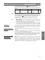
Optimum Cycle
Control
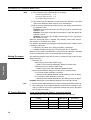
• Optimum cycle control is a control method in which the outputs are turned
ON/OFF each half cycle.
• Turning the outputs ON/OFF each half cycle can provide high-speed
response and high-precision temperature control while suppressing
noise.
• Use SSRs for single-phase heaters (with zero-cross function) for optimum
cycle control.
ON for 1/5 half cycles (20%)
MV 20%
Note
Soft-start Optimum
Cycle Control
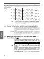
The image shows a current waveform with an MV of 20%.
• Soft-start optimum cycle control is a control method that combines phase
control and optimum cycle control.
• By smoothly switching between phase control and optimum cycle control,
it is possible to control the output and suppress the inrush current even
with loads with characteristics like halogen heaters.
• Use SSRs for single-phase heaters (without zero-cross function) for softstart optimum cycle control.
• The control method is switched at the Switching MV threshold.
31
Functions
2. After setting the SSR Selector, enable the new setting by executing a software reset with an Operation Command or turning the power OFF and
then ON again.
Section 4-2
Selecting the SSR (Control Method) 4 or 8-channel Models)
• Set the soft increase and soft decrease times to control the output. For
details on these settings, refer to 4-9 Setting the Soft Increase and Soft
Decrease Times (4 and 8-channel Models) on page 49.
• Current detection is not performed during phase control. The current values (heater ON current, heater OFF current, and actual current) will be 0
A, and the current alarms (heater burnout detection, heater overcurrent
detection, and SSR short-circuit detection) will always be OFF.
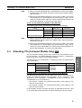
Setting the Switching MV
Threshold
The Switching MV Threshold is used in soft-start optimum cycle control. By
setting the Switching MV Threshold, the control method can be switched to
phase control below the set value and optimum cycle control above the set
value.
The default value is set to 20%.
Variable
type
85/C5
Parameter name
Setting range
Switching MV threshold for
channels 1 to 8
Default
0.0% to 100.0%
20.0
Example: Performing Soft-start Optimum Cycle Control in Channel 1 with a
Switching MV Threshold of 40.0%, an MV of 100.0%, and a Soft Increase
Time of 20 s
1,2,3...
1. Set the Channel 1 Switching MV Threshold to 40.0%, and the Channel 1
MV to 100.0% with a Variable Area Write command.
2. The channel 1 Soft Increase time is kept at its default value, so it is not necessary to set this value.
3. Once the Channel 1 Switching MV Threshold is written, the setting is
saved, and will also be effective the next time that the power is turned ON.
MV
Functions
100.0%
Time
40.0%
Soft increase time (20 s)
Phase control
Note
Three-phase
Optimum Cycle
Control
Optimum cycle control
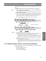
The image shows a current waveform.
• Three-phase optimum cycle control is a control method in which the outputs are turned ON/OFF every two cycles.
• Turning the outputs ON/OFF every two cycles allows optimum cycle control to be used with three-phase heaters.
• Use SSRs for three-phase heaters with zero-cross function for threephase optimum cycle control.
32
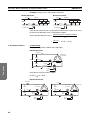
Section 4-3
Selecting the CT (4-channel Models Only)
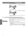
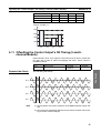
The following diagram shows an example connection to a three-phase heater.
1. Phase R
2. Phase S
3. Phase T
Load power supply
G3ZA
Trigger signal
SSR
Control power supply
CT (4-channel models only)
Load
When the G3ZA is connected as shown above and the MV is 50%, the
phases will have the current waveforms shown in the following diagram.
Load power supply
Phase R-S
Functions
Phase S-T
Phase R-T
4-3
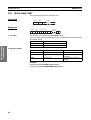
Selecting the CT (4-channel Models Only) V2
The selected CT setting determines the displayable current range, as shown
in the following table.
Variable
type
83/C3
Parameter name
Current Monitor
Selector (See note
1.)
Setting
Min. monitor Max. monitor
value
value (See
note 3.)
0: (0 to 50 A)
0A
1: (0 to 150 A)
0A
2: (0% to
100%) (See
note 2.)
0%
55 A (See
note 3.)
165 A (See
note 3.)
110% (See
note 3.)
Default
0
(0 to 50 A)
33
Section 4-3
Selecting the CT (4-channel Models Only)
Note
(1) The resolution of the monitor display is as follows.
0 to 50 A range selected:
0 to 150 A range selected:
1A
3A
0% to 100% range selected: 2%
(2) The heater burnout detection, heater overcurrent detection, and SSR
short-circuit detection values must be set as percentages.
(3) When the input exceeds the maximum value, the display will overflow at
the maximum value.
Example: If the range is 0 to 50 A and the input is 60 A, the display will
overflow at 55 A.
Example: If the range is 0 to 150 A and the input is 170 A, the display will
overflow at 165 A.
Example: If the range is 0% to 100% and the input is 115%, the display
will overflow at 110%.
When the percentage input is selected, the maximum current value measurable with the CT is measured as 100%.
For example, the following percentages will be displayed when a 30-A current
is flowing in the heater.
• If a E54-CT1 (0 to 50 A) CT is being used, 60% is displayed.
• If a G3ZA-CT150L (0 to 150 A) CT is being used, 20% is displayed.
Similarly, the heater burnout detection, heater overcurrent detection, and SSR
short-circuit detection values are also detected as percentages.
Setting Procedure
The following examples show how to select a suitable CT and set the Current
Monitor Selector.
• Select the CT.
• Detecting current in the 0 to 50 A range
→ Select a CT for 0 to 50 A detection (E54-CT1 or E54-CT3).
Functions
• Detecting current in the 0 to 150 A range
→ Select a CT for 0 to 150 A detection (G3ZA-CT150L).
• Set the Current Monitor Selector to match the CT selected above.
• If a CT for 0 to 50 A detection is selected:
→ Set the Current Monitor Selector to 0 (0 to 50 A) or 2 (0% to 100%).
• If a CT for 0 to 150 A detection is selected:
→ Set the Current Monitor Selector to 1 (0 to 150 A) or 2 (0% to 100%).
Example: Setting the Current Monitor Selector to the 0 to 150 A Range
1,2,3...
1. Set the Current Monitor Selector to 1 with a Variable Area Write command.
2. After setting the Current Monitor Selector, enable the new setting by executing a software reset with an Operation Command or turning the power
OFF and then ON again.
CT Current Monitors
CT for 0 to 50 A Detection (E54-CT1 or E54-CT3) Selected
The following table shows representative currents that are detected.
Current Monitor Selector
0: 0 to 50 A
setting
Minimum monitored value 0 A
34
1: 0 to 150 A
(See note 1.)
---
2: 0% to 100%
(See note 2.)
0%
10 A
50 A
-----
20%
100%
Maximum monitored value 55 A
---
110%
Section 4-4
Allocating CTs (4-channel Models Only)
Note
(1) When a CT for 0 to 50 A detection is selected, do not set the Current Monitor Selector to 1 (0 to 150 A). The correct current value cannot be detected if it is set to 1.
(2) When the Current Monitor Selector is set to 2 (0% to 100%), the current
will be displayed as a percentage of the connected CT's range. (For example, the current will be 100% for a 50-A current flowing through a CT
for 0 to 50 A detection, as shown in the table above.)
CT for 0 to 150 A Detection (G3ZA-CT150L) Selected
The following table shows representative currents that are detected.
Current Monitor Selector
setting
Note
0: 0 to 50 A
1: 0 to 150 A
(See note 1.)
2: 0% to 100%
(See note 2.)
Minimum monitored value -----
0A
30 A
0%
20%
--Maximum monitored value ---
150 A
165 A
100%
110%
(1) When a CT for 0 to 150 A detection is selected, do not set the Current
Monitor Selector to 0 (0 to 50 A). The correct current value cannot be detected if it is set to 0.
(2) When the Current Monitor Selector is set to 2 (0% to 100%), the current
will be displayed as a percentage of the connected CT's range. (For example, the current will be 100% for a 150-A current flowing through a CT
for 0 to 150 A detection, as shown in the table above.)
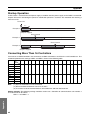
Allocating CTs (4-channel Models Only) V2
The CT allocation settings specify which currents are measured for the outputs of channels 1 to 4. When detecting abnormal current in a single-phase
heater, leave these settings at their default settings.
A heater burnout can be detected in a three-phase heater by allocating two
CTs to one output.
Variable type
Parameter name
83/C3
CT1 Allocation
CT2 Allocation
CT3 Allocation
CT4 Allocation
Setting range
0: Disabled
1: Channel 1
2: Channel 2
3: Channel 3
4: Channel 4
Default
1
2
3
4
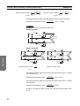
Example Settings for Detection of Three-phase Heater Burnout
The following measurements can be made when the CTs are connected as
shown in the following diagram, CT1 Allocation is set to 1 (channel 1), CT2
Allocation is set to 1 (channel 1), CT3 Allocation is set to 2 (channel 2), and
CT4 Allocation is set to 2 (channel 2).
• The channel 1 outputs are synchronized and the current inputs to CT1
and CT2 are measured.
• The channel 2 outputs are synchronized and the current inputs to CT3
and CT4 are measured.
In this example, all of the CT inputs (4 inputs) are allocated to channels 1 and
2, so a three-phase heater burnout cannot be detected in channels 3 and 4.
35
Functions
4-4
Section 4-5
Detecting Heater Burnouts (4-channel Models Only)
Loads Connected to Channel 1
17.3 A
Lo
17.3 A
200 V
ad
200 V
200 V
CT1: Measures the current of channel 1.
CT2: Measures the current of channel 1.
Lo
ad
Load such
as a heater
Load
To CT1
input
CT1
17.3 A
CT2
To CT2
input
Loads Connected to Channel 2
17.3 A
Lo
17.3 A
200 V
ad
200 V
200 V
CT3: Measures the current of channel 2.
CT4: Measures the current of channel 2.
Lo
ad
Load such
as a heater
Load
To CT3
input
CT3
CT4
17.3 A
To CT4
input
For details on heater burnout detection, refer to 4-5 Detecting Heater Burnouts (4-channel Models Only).
4-5
Detecting Heater Burnouts (4-channel Models Only)
Functions
A heater burnout is detected by determining if the heater current is below the
heater burnout detection value when a control output is ON. In addition, the
abnormal current detection delay can be set to prevent noise from causing
false burnout detection.
Setting Procedure
Make the following settings to detect heater burnout. If these settings are not
made, heater burnout may not be detected properly.
• Wire the CTs.
• Calculate the detection value as described under the heading Calculating
the Heater Burnout Detection Value on page 39, and set the heater burnout detection value.
• Set the abnormal current detection delay as described in 4-13 Setting the
Abnormal Current Detection Delay (4 and 8-channel Models) V2 on
page 52
36
Section 4-5
Detecting Heater Burnouts (4-channel Models Only)
Heater Burnout
Detection Timing
Hysteresis
Load current
(SSR output)
Heater burnout
detection value
G3ZA output
G3ZA alarm
A
Note
B
This example shows operation with the following settings:
Abnormal current detection delay = 0 (immediate alarm)
Operation at error = 0 (Continue with error clear)
• Heater burnout is detected at point 1 in the diagram above. The detection
condition is as follows:
Heater ON current (see note 1) ≤ Heater burnout detection value.
Heater ON current (see note 1) ≥ Heater burnout detection value + Hysteresis (see note 2)
Note
(1) The heater ON current is the peak load current that flows when the
G3ZA's output is ON.
(2) The hysteresis setting applies a dead zone between the detection condition and clearing condition, which prevents ON/OFF chattering of the
alarm. The same hysteresis setting is used for the heater burnout detection, heater overcurrent detection, and SSR short-circuit detection functions.
Variable type
81/C1
83/C3
Note
Parameter name
Setting range
Default
Channel 1 to 4 heater burnout
detection value
0 to 50 A (See note.) 0 (Disabled)
CT 1 to 4 heater burnout
detection value ( V2 )
0 to 165 A, or %
(See note.)
0 (Disabled)
Hysteresis
1 to 10 A, or %
1
If set to 0 A, heater burnout will not be detected.
If set to 50 A (or 165 A in the V2 models), detection is forced. Use these settings to confirm operation during installation.
37
Functions
• The heater burnout alarm is cleared at point 2 in the diagram above. The
clearing condition is as follows:
Section 4-5
Detecting Heater Burnouts (4-channel Models Only)
Setting Ranges Supported in the V2 Models (0 to 165 A, or %)
The current range and units are determined by the Current Monitor Selector
setting.
Variable type
Parameter name
83/C3
Current Monitor Selector
Note
0
Setting
Current range
0 to 55
Units
A
1
2
0 to 165
0 to 110
A
%
Detection values of 0 to 165 (A or %) max. can be detected, but set the detection value appropriate for the current range. If the detection value is set above
the current range, errors will not be detected. Refer to 4-3 Selecting the CT (4channel Models Only) V2 on page 33 for details on detection values.
Example: Setting the CT1 Heater Burnout Detection Value to 20 A
1,2,3...
1. Set the CT1 heater burnout detection value to 20 with a Variable Area
Write command.
2. The current is detected in CT1, and heater burnout is detected with the timing shown in the diagram on the preceding page.
3. Once the CT1 heater burnout detection value is written, the setting is
saved, and will also be effective the next time that the power is turned ON.
Precautions
• Turn ON the heater power supply at the same time or before turning ON
the G3ZA power supply. False detection will occur if the heater power
supply is turned ON after the G3ZA power supply.
• The actual current flowing in the heater may not be the same as the
heater's rated current. Check the heater current under actual conditions
using the CT1 to CT4 Heater ON currents.
Functions
• Detection will be unstable if there is only a small difference between the
normal current and burnout current. To achieve stable detection, set the
parameters as follows.
• For a Current Monitor Selector setting of 0 (0 to 50 A):
Heaters of less than 10 A: (Normal current - Burnout current) ≥ 2 A
Detection will not be stable if the difference is less
than 2 A.
Heaters of 10 A or more: (Normal current - Burnout current) ≥ 3 A
Detection will not be stable if the difference is less
than 3 A.
• For a Current Monitor Selector setting of 1 (0 to 150 A):
Heaters of less than 10 A: (Normal current - Burnout current) ≥ 6 A
Detection will not be stable if the difference is less
than 6 A.
Heaters of 10 A or more: (Normal current - Burnout current) ≥ 9 A
Detection will not be stable if the difference is less
than 9 A.
• For a Current Monitor Selector setting of 2 (0% to 100%):
Heaters of less than 10 A: (Normal current - Burnout current) ≥ 4%
Detection will not be stable if the difference is less
than 4%.
Heaters of 10 A or more: (Normal current - Burnout current) ≥ 6%
Detection will not be stable if the difference is less
than 6%.
If the conditions for stable detection cannot be met, increase the number of
turns of the heater wire through the current transformer and increase the
detection value. The monitored heater ON current value is proportional to the
number of turns.
38
Section 4-5
Detecting Heater Burnouts (4-channel Models Only)
Example:
• Each channel's status can be read individually to check it for heater burnout detection.
Operation after Error
Detection
It is possible to select the Controller's operation after a heater burnout is
detected.
For details on selecting operation after an error, refer to 4-14 Setting Operation at Error (4 and 8-channel Models) on page 53.
Calculating the Heater
Burnout Detection
Value
Use the following formula to calculate the heater burnout detection value.
Heater burnout detection value =
Note
(Normal current + Burnout current)
2
The result is an integer display.
When two or more heaters are connected through the current transformer, set
the burnout detection value to detect burnouts on the heater with the smallest
current. (If the heater currents are all the same, set the value for burnout of one
wire.)
Application Examples
Example 1: Using One 1-kW Heater (200 V AC)
Normal operation
Burnout occurred
AC line
5A
200 V
AC line
200 V
Load
5A
0A
Wire
break
CT
Functions
1. Single-phase Heaters
Load
CT
To CT input
To CT input
If the normal heater current is 5 A and the burnout heater current is 0 A, the
heater burnout detection value is calculated as follows:
Heater burnout detection value =
=
(Normal current + Burnout current)
2
5+0
2
= 2.5 → 2 [A]
39
Section 4-5
Detecting Heater Burnouts (4-channel Models Only)
Example 2: Using Three 1-kW Heaters (200 V AC)
Normal operation
15 A
Burnout occurred
AC line
200 V
AC line
10 A
Load
Load
Load Load
Wire
break
200 V
Load
10 A
15 A
CT
Load
CT
To CT input
To CT input
If the normal heater current is 15 A and the burnout heater current is 10 A, the
heater burnout detection value is calculated as follows:
(Normal current + Burnout current)
Heater burnout detection value =
2
15 + 10
=
2. Three-phase Heaters
= 12.5 A → 12 [A]
2
a. Delta Wiring
Example: Using Three 4-kW Heaters (200 V AC)
Normal Operation:
34.6 A
Load such
as a heater
ad
Lo
ad
200 V
Lo
200 V
34.6 A
Load
CT
Functions
200 V
To CT
input
CT
34.6 A
To CT
input
Each phase's normal current is 34.6 A.
34.6 A (
3 × 20 A)
Burnout Occurred:
Wire break
Load
200 V
34.6 A
200 V
CT
To CT
input
40
CT
To CT
input
30 A
ad
Load
CT
200 V
Wire break
Lo
Lo
30 A
Load such
as a heater
200 V
ad
Lo
200 V
ad
Lo
Load such
as a heater
200 V
ad
20 A
To CT
input
20 A
CT
To CT
input
Section 4-5
Detecting Heater Burnouts (4-channel Models Only)
Burnout current = 20 A ×
3
2
3 ×
Burnout current = 20 A ×
= 30 A
1
3
3 ×
= 20 A
The following formula yields the heater burnout current when there is a break
in the load wiring.
Heater burnout detection value =
34.6 + 30
2
= 32.3 → 32 [A]
The following formula yields the heater burnout current when there is a break
in the load itself.
Heater burnout detection value =
34.6 + 20
2
= 27.3 → 27 [A]
To detect a wire break at either location, set a heater burnout detection value
of 32 A.
b. Star Wiring
Example: Using three 6-kW heaters (200 V AC)
Normal Operation:
Load
17.3 A
200 V
ad
ad
Lo
17.3 A
Lo
200 V
Load such
as a heater
CT
200 V
17.3 A
Functions
To CT
input
CT
To CT
input
Each phase's normal current is 17.3 A.
17.3 A
30 A ×
1
3
Burnout Occurred:
Wire
break
ad
15 A
200 V
ad
200 V
Lo
Lo
200 V
ad
200 V
15 A
CT
ad
CT
CT
To CT input
Lo
Wire
break
200 V To CT input
200 V To CT input
15 A
Load
Load such
as a heater
Lo
Load such
as a heater
Load
15 A
CT
To CT input
41
Section 4-5
Detecting Heater Burnouts (4-channel Models Only)
1
3
Burnout current = 30 A ×
×
3
2
Burnout current = 30 A ×
= 15 A
1
3
×
3
2
= 15 A
The following formula yields the heater burnout current for the main wiring.
Heater burnout detection value =
17.3 + 15
2
= 16.15 → 16 [A]
c. V Wiring
Example: Using two 2-kW heaters (200 V AC)
Normal Operation:
10 A
CT
200 V
200 V
ad
Lo
Load such
as a heater
To CT input
ad
Lo
17.3 A
200 V
CT
10 A
To CT input
Burnout Occurred:
10 A
5A
CT
200 V
200 V
10 A
200 V
To CT
input
Load such
as a heater
CT
5A
CT
To CT
input
Burnout current = 10 A ×
To CT
input
1
2
ad
Lo
ad
Lo
Functions
200 V
200 V
ad
Lo
Load such
as a heater
Wire
200 V
break
CT
d
a
Lo
To CT
input
Wire
break
Burnout current = 0 A
=5A
The following formula yields the heater burnout current when there is a break
in the common wire.
Heater burnout detection value =
10 + 5
2
= 7.5 → 7 [A]
The following formula yields the heater burnout current when there is a break
in the load wire.
Heater burnout detection value =
10 + 0
2
= 5 [A]
To detect a wire break at either location, set a heater burnout detection value
of 7 A.
42
Section 4-6
Detecting Heater Overcurrent (4-channel Models Only)
4-6
Detecting Heater Overcurrent (4-channel Models Only)
Heater overcurrents are detected by determining whether the heater current is
above the heater overcurrent detection value when a G3ZA control output is
ON. The abnormal current detection delay can be set to prevent false overcurrent detection due to noise.
Setting Procedure
Make the following settings to detect heater overcurrent. If these settings are
not made, heater overcurrent may not be detected properly.
• Wire the CTs.
• Calculate the detection value that is appropriate for the application, and
set the heater overcurrent detection value.
• Set the abnormal current detection delay as described in 4-13 Setting the
Abnormal Current Detection Delay (4 and 8-channel Models) V2 on
page 52.
Heater Overcurrent
Detection Timing
Hysteresis
Heater overcurrent
detection value
Load current
(SSR output)
Functions
G3ZA output
G3ZA alarm
A
Note
B
This example shows operation with the following settings:
Abnormal current detection delay = 0 (immediate alarm)
Operation at error = 0 (Continue with error clear)
• Heater overcurrent is detected at point 1 in the diagram above. The detection condition is as follows:
Heater ON current (see note 1) ≥ Heater overcurrent detection value.
• The heater overcurrent alarm is cleared at point 2 in the diagram above.
The clearing condition is as follows:
Heater ON current (see note 1) ≤ Heater overcurrent detection value −
Hysteresis (see note 2)
Note
(1) The heater ON current is the peak load current that flows when the
G3ZA's output is ON.
(2) The hysteresis setting applies a dead zone between the detection condition and clearing condition, which prevents ON/OFF chattering of the
alarm. The same hysteresis setting is used for the heater burnout detec-
43
Section 4-6
Detecting Heater Overcurrent (4-channel Models Only)
tion, heater overcurrent detection, and SSR short-circuit detection functions.
Variable type
Parameter name
Setting range
Default
81/C1
Channel 1 to 4 heater overcur- 0 to 50 A (See note.) 50 (Disabled)
rent detection value
CT 1 to 4 heater overcurrent
83/C3
Note
detection value ( V2 )
0 to 165 A, or %
(See note.)
165 (Disabled)
Hysteresis
1 to 10 A, or %
1
If set to 50 A (or 165 A in the V2 models), heater overcurrent will not be
detected. If set to 0, detection is forced. Use these settings to confirm operation during installation.
Setting Ranges Supported in the V2 Models (0 to 165 A, or %)
The current range and units are determined by the Current Monitor Selector
setting.
Variable type
83/C3
Note
Parameter name
Current Monitor Selector
Setting
Current range
Units
0
1
0 to 55
0 to 165
A
A
2
0 to 110
%
Detection values of 0 to 165 (A or %) max. can be detected, but set the detection value appropriate for the current range. If the detection value is set above
the current range, errors will not be detected. Refer to 4-3 Selecting the CT (4channel Models Only) V2 on page 33 for details on detection values.
Example: Setting the CT1 Heater Overcurrent Detection Value to 20 A
Functions
1,2,3...
1. Set the CT1 heater overcurrent detection value to 20 with a Variable Area
Write command.
2. The current is detected in CT1, and heater overcurrent is detected with the
timing shown in the diagram on the preceding page.
3. Once the CT1 heater overcurrent detection value is written, the setting is
saved, and will also be effective the next time that the power is turned ON.
Precautions
• The actual current flowing in the heater may not be the same as the
heater's rated current. Check the heater current under actual conditions
using the CT1 to CT4 Heater ON currents.
• Detection will be unstable if there is only a small difference between the
normal current and the overcurrent setting. To achieve stable detection,
set the parameters as follows:
• For a Current Monitor Selector setting of 0 (0 to 50 A):
Heaters of less than 10 A: (Normal current - Overcurrent setting) ≥ 2 A
Detection will not be stable if the difference is less
than 2 A.
Heaters of 10 A or more: (Normal current - Overcurrent setting) ≥ 3 A
Detection will not be stable if the difference is less
than 3 A.
• For a Current Monitor Selector setting of 1 (0 to 150 A):
Heaters of less than 10 A: (Normal current - Overcurrent setting) ≥ 6 A
Detection will not be stable if the difference is less
than 6 A.
44
Detecting SSR Short-Circuits (4-channel Models Only)
Section 4-7
Heaters of 10 A or more: (Normal current - Overcurrent setting) ≥ 9 A
Detection will not be stable if the difference is less
than 9 A.
• For a Current Monitor Selector setting of 2 (0% to 100%):
Heaters of less than 10 A: (Normal current - Overcurrent setting) ≥ 4%
Detection will not be stable if the difference is less
than 4%.
Heaters of 10 A or more: (Normal current - Overcurrent setting) ≥ 6%
Detection will not be stable if the difference is less
than 6%.
• Each channel's status can be read individually to check it for heater overcurrent detection.
Operation after Error
Detection
It is possible to select the Controller's operation after a heater overcurrent is
detected.
For details on selecting operation after an error, refer to 4-14 Setting Operation at Error (4 and 8-channel Models) on page 53.
Calculating the Heater
Overcurrent
Detection Value
4-7
Set a heater overcurrent detection value appropriate for the customer's application.
Detecting SSR Short-Circuits (4-channel Models Only)
Setting Procedure
Make the following settings to detect an SSR short-circuit. If these settings are
not made, SSR short-circuits may not be detected properly.
• Wire the CTs.
• Calculate the detection value as described under the heading Calculating
the SSR Short-Circuit Detection Value on page 47, and set the SSR
short-circuit detection value.
• Set the abnormal current detection delay as described in 4-13 Setting the
Abnormal Current Detection Delay (4 and 8-channel Models) V2 on
page 52.
45
Functions
An SSR short-circuit is detected by determining whether the heater current is
above the SSR short-circuit detection value when a G3ZA control output is
OFF. The abnormal current detection delay can be set to prevent false SSR
short-circuit detection due to noise.
Section 4-7
Detecting SSR Short-Circuits (4-channel Models Only)
SSR Short-Circuit
Detection Timing
Hysteresis
SSR short-circuit
detection value
Load current
(SSR output)
G3ZA output
G3ZA alarm
A
Note
B
This example shows operation with the following settings:
Abnormal current detection delay = 0 (immediate alarm)
Operation at error = 0 (Continue with error clear)
• An SSR short-circuit is detected at point 1 in the diagram above. The
detection condition is as follows:
Heater OFF current (see note 1) ≥ SSR short-circuit detection value.
• The heater short circuit alarm is cleared at point 2 in the diagram above.
The clearing condition is as follows:
Functions
Heater OFF current (see note 1) ≤ SSR short-circuit detection value - Hysteresis (see note 2)
Note
(1) The heater OFF current is the peak load current that flows when the
G3ZA's output is OFF.
(2) The hysteresis setting applies a dead zone between the detection condition and clearing condition, which prevents ON/OFF chattering of the
alarm. The same hysteresis setting is used for the heater burnout detection, heater overcurrent detection, and SSR short-circuit detection functions.
Variable type
81/C1
Parameter name
Setting range
Default
Channel 1 to 4 SSR short-circuit detection value
0 to 50 A (See note.) 50 (Disabled)
CT 1 to 4 SSR short-circuit
detection value ( V2 mod-
0 to 165 A, or% (See 165 (Disnote.)
abled)
els)
83/C3
Note
46
Hysteresis
1 to 10 A, or %
1
If set to 50 A (or 165 A in the V2 models), SSR short-circuit will not be
detected. If set to 0 A, detection is forced. Use these settings to confirm operation during installation.
Section 4-7
Detecting SSR Short-Circuits (4-channel Models Only)
Setting Ranges Supported in the V2 Models (0 to 165 A, or %)
The current range and units are determined by the Current Monitor Selector
setting.
Variable type
Parameter name
83/C3
Current Monitor Selector
Note
0
Setting
Current range
0 to 55
Units
A
1
2
0 to 165
0 to 110
A
%
Detection values of 0 to 165 (A or %) max. can be detected, but set the detection value appropriate for the current range. If the detection value is set above
the current range, errors will not be detected. Refer to 4-3 Selecting the CT (4channel Models Only) V2 on page 33 for details on detection values.
Example: Setting the CT1 SSR short-circuit detection value to 20 A
1,2,3...
1. Set the CT1 SSR short-circuit detection value to 20 with a Variable Area
Write command.
2. The current is detected in CT1, and SSR short-circuits are detected with
the timing shown in the diagram on the preceding page.
3. Once the CT1 SSR short-circuit detection value is written, the setting is
saved, and will also be effective the next time that the power is turned ON.
Precautions
The actual current flowing in the heater may not be the same as the heater's
rated current. Check the heater current under actual conditions using the CT1
to CT4 Heater OFF currents.
Operation after Error
Detection
It is possible to select the Controller's operation after an SSR short-circuit is
detected.
When an SSR short-circuit has been detected, it is possible that the SSR has
failed in the always-ON state so that it cannot control operation. Consider
installing a failsafe circuit to cut off the power supply to the heater.
Calculating the SSR
Short-Circuit
Detection Value
Set an SSR short-circuit detection value appropriate for the customer's application.
As a rule, set a detection value that is at least two times the normal heater
OFF current. Proper detection may not be possible if a value that is less than
two times the normal heater OFF current is set. In additions, short-circuit
detection value is set to 0 A, so set a detection value of at least 1 A.
47
Functions
For details on selecting operation after an error, refer to 4-14 Setting Operation at Error (4 and 8-channel Models) on page 53.
Section 4-8
Detecting Communications Timeouts (4 and 8-channel Models)
4-8
Detecting Communications Timeouts (4 and 8-channel
Models)
Operation can be stopped if communications cannot be performed normally
for longer than the communications timeout time. In addition to stopping operation, the MV after communications error setting can also be set to output an
MV to each channel after a communications error is detected.
With the upgraded V2 models, the communications timeout time can be set
in seconds.
Host device
Communications
Operating
G3ZA
Stopped
Communications timeout time
Variable type
Parameter name
83/C3
Communications timeout time
Communications timeout time
2 (See note 1.) ( V2 only)
Note
Setting range
0: Disabled
1 to 60 min
Default
0 (Disabled)
0: Disabled
1 to 3,600 s
0 (Disabled)
(1) When the communications timeout time (minutes) is set, the same time
will be reflected in communications timeout time 2 (seconds). For example, a setting of 1 minute will become 60 s.
(2) Communications timeouts will not be detected if the time is set to 0.
Functions
(3) The new setting will become valid and detection of communications timeouts will start after executing a software reset with an Operation Command or turning the power OFF and then ON again.
When a communications timeout is detected, operation will stop, and the communications error flag in the status, the ERROR indicator, and the alarm output will turn ON. To clear the error, execute a software reset or start command
with an Operation Command.
Error status
ERROR indicator
All channels ON
Lit
Auxiliary output
Control output (Run)
ON
All channels stopped. The “MV after communications error” value will be output.
Execute a software reset or start command
with an Operation Command.
Clearing method
Example: Setting the communications timeout time to 20 seconds
1,2,3...
1. Set “communications timeout time 2” to 20 with a Variable Area Write command.
2. After setting communications timeout time 2, enable the new setting by executing a software reset with an Operation Command or turning the power
OFF and then ON again.
48
Setting the Soft Increase and Soft Decrease Times (4 and 8-channel Models)
Setting the MV after
Communications
Error
When a communications timeout has been detected, the preset MV after
communications error value can be output at each channel.
Use a Variable Area Write command to set the Channel 1 to 8 MV after communications error settings.
Variable type
85/C5
Note
4-9
Section 4-9
Parameter name
Setting range
Channel 1 to 8 MV after communications error
0.0% to 100.0%
Default
0.0
The Soft Increase and Soft Decrease times are applied to the “MV after communications error” outputs.
Setting the Soft Increase and Soft Decrease Times (4 and
8-channel Models) V2
The Soft Increase Time and Soft Decrease Time can be set to smoothly
change the output level. The Soft Increase and Soft Decrease times can be
set for each channel. Also, either one of the times can be set and used alone.
Variable type
85/C5
Note
Parameter name
Setting range
Channel 1 to 8 Soft Increase
Time
Channel 1 to 8 Soft Decrease
Time
0.0 to 99.9 s
0.0 to 99.9 s
Default
20.0 (See
note.)
0.0 (See
note.)
(1) If the Soft Increase or Soft Decrease Time is not being used, set it to 0.0
s (disabled).
(2) Only the Soft Increase Time is set to 20.0% as a default setting.
The Soft Increase Time sets the time it takes for the MV to go from 0% to
100% of its value, and the Soft Decrease Time sets the time it takes for the
MV to go from 100% to 0% of its value.
Since these are continuously changed parameters, they can be changed during operation.
Soft Increase Time
Soft Decrease Time
Manipulated variable (MV)
Manipulated variable (MV)
100%
100%
0
Time
Soft Increase Time
0
Time
Soft Decrease Time
Example: Setting the channel 1 Soft Increase Time to 50.0 s, and the channel
1 Soft Decrease Time to 30.0 s
1,2,3...
1. Set the channel 1 Soft Increase Time to 50.0 with a Variable Area Write
command.
2. Set the channel 1 Soft Decrease Time to 30.0 with a Variable Area Write
command.
3. When the settings are written, they are stored and become effective the
next time that the power is turned ON.
49
Functions
Soft Increase and Soft
Decrease Times Settings
Section 4-10
Changing the Manipulated Variable (4 and 8-channel Models)
Manipulated variable (MV)
100%
0
Time
Soft Increase
Time
Soft Decrease
Time
4-10 Changing the Manipulated Variable (4 and 8-channel
Models)
The Variable Area Write command is used to change the manipulated variable. The manipulated variable is 0.0% by default when the power supplied is
turned ON, but this value can be changed to a non-zero value with the Manipulated Variable Save operation command.
Example: Changing the manipulated variable to 20.0% when the power is
turned ON
1,2,3...
1. Set the manipulated variables to 20.0% for all channels with a Variable
Area Write command.
2. Execute the Manipulated Variable Save operation command.
3. The manipulated variables will be set to 20.0% the next time power is
turned ON.
Manipulated variable calculations can be used to set a channel's control variable based on another channel's manipulated variable. Set the control variable with the channel 1 to 8 source channel, channel 1 to 8 slope, and
channel 1 to 8 offset settings.
Using Manipulated
Variable Calculations
Functions
The following calculation method and set values can be used.
Control variable = (Source channel's MV × Slope ÷ 100.0) + Offset
The following table shows the default values, which will output 100% of each
channel's MV as the control variable.
Variable type
81/C1
Note
Parameter name
Setting range
Default
Channel 1 to 8 source channel Channel 1 to 8 (Set
the channel to use
as the source for
calculation.)
1 to 8
Channel 1 to 8 slope
Channel 1 to 8 offset
100.0
0.0
0.0 to 400.0%
−400.0 to 400.0%
(1) If the control variable exceeds the range of 0% to 100%, it will be clamped
at 0% or 100%.
(2) The control variable can be read using the Variable Area Read command.
Example: Setting the Other Channels' Control Variables Based on Channel
2's MV
The following values are set for each parameter with Variable Area Write commands.
50
Channel
Manipulated variable
0.0
1
20.0
2
0.0
3
0.0
4
Source channel
2
2
2
2
Section 4-11
Offsetting the Control Output's ON Timing (4 and 8-channel Models)
Slope
Channel
1
325.0
2
100.0
3
175.0
4
250.0
Offset
Control variable
15.0
80.0
0.0
20.0
5.0
40.0
10.0
60.0
Control variable (%)
80.0
60.0
40.0
20.0
ch1
ch2
ch3
ch4
4-11 Offsetting the Control Output's ON Timing (4 and 8channel Models)
Offset Control can be set to adjust the time when each channel's control output goes ON in order to reduce overlapping ON states. Offset Control is
enabled by default.
Variable type
Parameter name
81/C1
Offset control
Default
1 (Enabled)
The ON timing will overlap
Functions
Disabled (No Offset)
Setting range
0: Disabled
1: Enabled
ch1
ch2
ch3
ch4
Note
(1) The waveforms are current waveforms of the SSR load power supply voltage.
(2) The amount of overlapping depends on the control variables and the timing of control variable changes.
51
Section 4-12
Turning OFF a Control Output (4 and 8-channel Models)
Enabled (Offsets
Applied)
Overlapping of the ON outputs is reduced.
ch1
ch2
ch3
ch4
Note
(1) The waveforms are current waveforms of the SSR load power supply voltage.
(2) The amount of overlapping depends on the control variables and the timing of control variable changes.
4-12 Turning OFF a Control Output (4 and 8-channel Models)
Functions
Use the start/stop operation command to turn OFF control outputs. The start/
stop command can control individual channels, not just all channels at once.
For details on operation commands, refer to 3-6 Operation Command on
page 25.
!Caution Since the start/stop status is written to non-volatile memory, a channel will still
be stopped when power is turned back ON if the power is turned OFF while
the control output is stopped. To restart operation, use the Start/Stop operation command again.
4-13 Setting the Abnormal Current Detection Delay (4 and 8channel Models) V2
The abnormal current detection delay can be set to prevent false detection of
current errors (such as heater burnout) due to noise or other causes. Set a
suitable number of detections for the usage conditions.
Variable type
Parameter name
85/C5
Abnormal current detection
delay
Note
Setting range
0 to 200 detections
Default
3 (See note.)
To output an alarm immediately when an error is detected, set the delay to 0
(disabled).
When heater burnouts, heater overcurrents, and SSR short-circuits are being
detected, an abnormal current detection delay can be set to output an alarm
only when the number of consecutive errors exceeds the set number of detections.
If the number of detections is set to 0, an alarm will be output immediately
when an error is detected.
52
Section 4-14
Setting Operation at Error (4 and 8-channel Models)
Use the following example as a reference when setting the number of detections.
Example: Setting the Abnormal Current Detection Delay to 3 Detections
1,2,3...
1. Set the abnormal current detection delay to 3 detections (0000 0003 hex)
with a Variable Area Write command.
2. When the setting is written, it is stored and becomes effective the next time
that the power is turned ON.
3. An alarm is not output even if heater burnout is detected 3 times consecutively. A heater burnout will be detected and the alarm will be output only
when the heater burnout is detected consecutively 4 times or more.
Error value detected 4 consecutive times.
Alarm is output.
Heater burnout
detection value
Error value
detected once.
Detected
3 times.
Alarm is not output.
Heater burnout
detection value
(1) The image shows a current waveform.
(2) During optimum cycle control or soft-start optimum cycle control, the operation of the abnormal current detection delay is as follows:
Output ON/OFF control and Current error detection are performed
each half cycle, so the errors are detected and counted each half cycle.
During three-phase optimum cycle control, the operation of the abnormal
current detection delay is as follows:
Output ON/OFF control and Current error detection are performed every two cycles, so the errors are detected and counted once every two
cycles.
4-14 Setting Operation at Error (4 and 8-channel Models)
This setting can select the operation of the Controller after one of the following
errors has occurred.
• Zero cross error (See note 2.)
• Heater burnout detection
• Heater overcurrent detection
53
Functions
Note
Section 4-15
Monitoring the Effective Current
• SSR short-circuit detection
Variable type Parameter name
83/C3
Operation at Error
Setting range
0: Continue with error clear
1: Continue without error clear
2: Stop
Default
0
The following table shows the error clearing methods when an error is
detected.
Setting
0
Note
Operation at
Error
Continue with
error clear
Operation
Continues.
Error clearing method
When the Controller returns to normal
status, the error is cleared (i.e., the status flag, ERROR indicator, and alarm
output are turned OFF).
The error is not cleared even when the
Controller returns to normal status.
Restore normal status and then execute
a Start command with the Operation
Command.
1
Continue without error clear
Continues.
2
Stop
Affected chan- The error is not cleared and operation
nel stops. (See remains stopped even when the Connote 1.)
troller returns to normal status. Restore
normal status and then execute a Start
command with the Operation Command.
(1) Operation will stop for all channels if a zero cross error occurs.
(2) A zero cross error occurs when there is an error in the load power supply
voltage, frequency, or waveform. Refer to SECTION 5 Troubleshooting for
details.
Functions
Example: Setting the Operation at Error Setting to “Continue without Error
Clear”
1,2,3...
1. Set the Operation at Error to 1 with a Variable Area Write command.
2. When the setting is written, it is stored and becomes effective the next time
that the power is turned ON.
4-15 Monitoring the Effective Current V2
The G3ZA can monitor the current read by the CT sensor as the effective current. The following formula is used to calculate the effective current that is
actually displayed.
Effective current (A) = CT Current (A)/ (100/Control variable (%))
Note
(1) The display shows the current in 0.1 A units.
(2) The CT current is the heater ON current (the current flowing through the
heater when the control output is ON).
The effective current is monitored with the Variable Area Read command.
Variable type
8E/CE
Note
54
Parameter name
CT1 to CT4 effective current
Monitor range
Default
0.0 to 165.0 A, or % 0.0
(See note.)
The setting range is determined by the Current Monitor Selector setting. For
details, refer to 4-3 Selecting the CT (4-channel Models Only) V2 on
page 33.
Monitoring the Effective Current
Section 4-15
In the following cases, the display will indicate a value other than the effective
current.
• Operation is stopped or a communications error occurred: 0.0 A is displayed.
Functions
• Power is turned ON or a zero-cross error occurred: 0.0 A is displayed.
55
Functions
Monitoring the Effective Current
56
Section 4-15
SECTION 5
Troubleshooting
5-1
Errors. . . . . . . . . . . . . . . . . . . . . . . . . . . . . . . . . . . . . . . . . . . . . . . . . . . . . . . .
58
5-2
Handling Problems . . . . . . . . . . . . . . . . . . . . . . . . . . . . . . . . . . . . . . . . . . . . .
59
Troubleshooting
This section provides information on problems that may occur during operation and corrective measures for them.
57
Section 5-1
Errors
5-1
Errors
Error Table
Troubleshooting
ERROR
indicator
Status
Operation
Error
Correction
Cycle the power supply.
If operation does not recover, use the following
procedure, noting that all settings will be returned
to their default values.
• Error Response Received
Initialize the settings and perform a software
reset with an Operation Command.
• Error Response Not Received
Set the host data length, stop bits, and parity to
the default values for the G3ZA (if a Converter is
being used, set it to the same values) and then
initialize the settings and perform a software
reset with an Operation Command.
If operation still does not recover, the G3ZA
needs to be repaired.
• Check to see if the communications line is broken.
• Check to see if a communications error has
occurred.
• Check the host to see if it is functioning correctly.
• Check the information provided in 4-8 Detecting
Communications Timeouts (4 and 8-channel
Models) on page 48.
• Check to see if the load power supply's voltage
and frequency are within specifications. The
specified ranges are as follows:
Controllers with 100 to 240 V Load Voltage:
75 to 264 VAC
Controllers with 400 to 480 V Load Voltage:
340 to 528 VAC
Frequency (all models) : 47 to 63 Hz
• Noise may be a factor. Check the load power
supply line for noise and check the general area
around the G3ZA for noise.
Lit
No response or
an error
response
Stops
There is an
error in internal
memory or in
non-volatile
memory.
Lit
Communications error bit is
ON.
Stops
A communications timeout
has occurred.
Lit
Zero cross error According to the A zero cross
error has been
bit is ON.
operation at
error setting
detected.
Lit
Heater burnout
bit is ON.
Lit
Heater overcurrent bit is ON.
Flashing
SSR short-circuit bit is ON.
58
According to the A heater burnoperation at
out has been
error setting
detected.
• The heater has burned out. Repair the heater or
the heater line.
• Check the information provided in 4-5 Detecting
Heater Burnouts (4-channel Models Only) on
page 36.
According to the A heater over• An overcurrent has occurred to the heater.
current has
Return the current to the correct range.
operation at
error setting
been detected. • Check the information provided in Wiring Diagrams on page 12 and in 4-6 Detecting Heater
Overcurrent (4-channel Models Only) on
page 43.
According to the An SSR short- • The SSR has short-circuited. Replace the SSR.
operation at
circuit has been • Check the information provided in Wiring Diaerror setting
detected.
grams on page 12 and in 4-7 Detecting SSR
Short-Circuits (4-channel Models Only) on
page 45.
Section 5-2
Handling Problems
Handling Problems
Handling Problems
Preliminary Checks
Check item
Items to check
Is the power supply
turned ON?
If the power supply is turned ON, the READY indicator will be
lit.
Was wiring performed correctly?
Check all of the wiring.
Were settings performed correctly?
• Check the switches to see if they are set correctly.
• Read out the settings to see if they have been set correctly.
• Read out all settings to see if any of them are incorrect.
Handling Problems
Condition
Communications
cannot be performed.
Correction
• If the SD/RD indicator does not light when communications
are attempted, there is a problem with the communications
line. Check the wiring of the communications line.
• If a communications converter is being used, check the settings of the converter to see if they are correct.
• Check the settings of SW1 and SW2 to see if they agree with
the settings of the host.
• Check the data length, number of stop bits, and parity to see
if they are the same as the host. If any of the settings are
incorrect or if any are unknown, use the following method for
communications.
1. Set SW2 to 7. (If more than 16 communications unit numbers are used, set SW2 to F.)
2. Set the baud rate, data length, number of stop bits, and parity of the host to the default values for the G3ZA.
If a converter is being used, set the converter to the same
values.
3. This should enable communications. Change all settings to
the correct values.
• Check the communications line to see if it is correct.
Outputs do not turn
ON.
• Unless the OCC indicator is lit and the control variable is set
to 0.0%, then there is a problem in the wiring. Check the wiring of the control outputs.
• If the ERROR indicator is lit or flashing, refer to the corrections given in the Error Table on page 58.
Returning settings to • Initialize the settings with an Operation Command. All of the
default values
settings can be returned to their default values. Refer to the
Status Lists on page 65 in the Appendix for default values.
Current cannot be
detected correctly.
• Check to see if the CT setting in the G3ZA matches the CT
that is connected. Refer to 4-3 Selecting the CT (4-channel
Models Only) V2 .
An output is not stable.
• Check to see if the SSR setting in the G3ZA matches the
SSR that is connected. Refer to 4-2 Selecting the SSR (Control Method) 4 or 8-channel Models) V2 .
59
Troubleshooting
5-2
Troubleshooting
Handling Problems
60
Section 5-2
Appendix
Appendix
Specifications
Specifications
Ratings
Control power supply voltage
100 to 240 VAC (50/60 Hz)
Control power supply voltage range 85 to 264 VAC
Power consumption
Load power supply voltage
Load power supply voltage range
Manipulated variable inputs
Trigger outputs
Approx. 5.9 W
100 to 240 VAC
400 to 480 VAC
Controllers for 100 to 240 VAC: 75 to 264 VAC
Controllers for 400 to 480 VAC: 340 to 528 VAC
Indications
0.0% to 100.0% (via RS-485 communications)
One for each channel, 12 VDC ±15%, max. load current: 21 mA (with built-in
short-circuit protection circuit)
NPN open collector, one output
(Max. load voltage: 30 VDC, max. load current: 50 mA)
LED indicators
Ambient operating temperature
Ambient operating humidity
−10 to 55°C (with no icing or condensation)
25% to 85%
Storage temperature
Elevation
−25 to 65°C (with no icing or condensation)
2,000 m max.
Accessories
Instruction Sheet
Alarm output
Model
E54-CT1/E54-CT3
G3ZA-CT150L
CT input
Single-phase between 0 and 50 A AC
Single-phase between 0 and 150 A AC
Performance
Insulation resistance
Current range:0 to 50 A: ±3 A max.
0 to 150 A: ±9 A max.
0% to 100%: ±6% max.
100 MΩ min. (at 500 VDC) between primary and secondary
Dielectric strength
Vibration resistance
2,000 VAC, 50/60 Hz for 1 min between primary and secondary
Shock resistance
Weight of main body
300 m/s2 three times each in six directions along three axes
Approx. 200 g (including terminal cover)
Degree of protection
Memory backup
IP20
EEPROM (non-volatile memory), write life: 100,000 writes
Installation environment
Approved standards
Overvoltage category III, pollution degree 2 (according to IEC 60664-1)
UL508 (Listing), CSA22.2 No. 14
EN50178
EN61000-6-4 (EN55011: 1998, A1: 1999 Class A, Group 1)
EN61000-6-2: 2001
Vibration frequency: 10 to 55 to 10 Hz, acceleration: 50 m/s2 in X, Y, Z directions
Appendix
Current accuracy
61
Appendix
Model Numbers
Model Numbers
G3ZA-ABCDE-F-G
Number
Code
Specifications
A
No. of control points
4
8
4 channels
8 channels
B
C
Control method
Current transformer input
None
H
Optimum cycle control
Yes
D
Load power supply voltage
A
2
None
100 to 240 VAC
E
Communications specifications
4
03
400 to 480 VAC
RS-485
F
G
Communications protocol
International standards
FLK
UTU
CompoWay/F
Approved by TÜV.
Current Transformer
Specifications
Item
Model number
E54-CT1
Max. continuous heater current
Dielectric strength
50 A
1,000 VAC for 1 min
Vibration resistance
Weight
98 m/s2, 50 Hz
Approx. 11.5 g
Accessories
None
Specification
E54-CT3
G3ZA-CT150L
120 A (See note.)
150 A
2,000 VAC for 1 min
Approx. 50 g
Approx. 130 g
Connection terminals (2) None
Plugs (2)
Note The maximum continuous current of the G3ZA together with the E54-CT3 is 50 A.
Dimensions (Unit: mm)
E54-CT1
21
15
7.5
2.8
3
10.5
25
5.8 dia.
40
Appendix
10
Two, 3.8 dia.
30
62
Appendix
E54-CT3
2.36 dia.
9
30
40
12 dia.
40
15
Two, M3 holes, depth: 4
30
G3ZA-CT150L
1.7
1.7
9.3
9.3
11
63
54
4.7
26MAX
20
Four, M4 × 6
50
8.5
17
13.5
di
a.
34.5
30
81.5
33.5
6
14.5
57
86
14.5
5.2
10
20
10
1.8
76
5.9
Appendix
4.1
63
Appendix
Startup Operation
It takes about 1 second for the load power supply to stabilize after the power supply to the G3ZA is turned ON.
Outputs will not turn ON during this period. A stabilization period of 1 second is also executed after clearing a
zero cross error.
Power ON
1s
Example 1 Stabilization
Normal operation
Outputs stopped
Error cleared
Example 2
Normal operation
Stabilization
Zero cross error
Outputs stopped
Error cleared
Example 3 Stabilization Normal operation
Zero cross error
Stabilization Normal operation
Outputs stopped
Outputs stopped
Connecting More Than 16 Controllers
If more than 16 G3ZA Controllers are connected, set SW2 to between 8 and B for the 17th Controller on. The
relationship between the settings of SW1 and SW2 is shown in the following table.
kbit/s
sw1
9.6
sw2
0
19.2
38.4
1
2
57.6
---
3
4 to 7
9.6
19.2
8
9
38.4
57.6
A
B
---
C to F
Note
0
1
2
3
4
5
6
7
8
9
A
B
C
00
01
02
03
04
05
06
07
08
09
10
11
12
16
17
18
19
20
21
22
23
24
25
26
27
28
D
E
F
13
14
15
29
30
31
(1) Up to 31 Controllers can be connected.
(2) Do not set SW2 to between 4 and 7 or C and F.
(3) It's easiest to set the communications unit number first and then the baud rate.
Setting example: The following settings would be used to set a Controller to communications unit number 7
and a baud rate of 38.4 kbit/s.
Appendix
SW1 = 7 and SW2 = 2
64
Appendix
Status Lists
Use the status listed in the following tables to check G3ZA status.
Status
Bit
31 to 13
Not used.
Status
OFF
OFF
---
ON
12
11
Start/stop
Not used.
Operating
OFF
Stopped
---
10
9
Not used.
Alarm output (applies to all channels)
OFF
OFF
--ON
8
7
Control output
Not used.
OFF
OFF
ON
---
6
5
Not used.
Communications error (applies to all channels)
OFF
No
--Yes
4
3
Zero cross error (applies to all channels)
Not used.
No
OFF
Yes
---
2
Heater overcurrent
No
Yes
1
0
SSR short-circuit
Heater burnout
No
No
Yes
Yes
Operating
Output
Error
Condition
Alarm output and zero cross error bit are ON.
Status
H’00000210
Stopped with no errors
H’00001000
Appendix
Example:
65
Appendix
Parameter List
If variables without parentheses are used in communications, the set values will be eight-digit (double-word)
data. If variables with parentheses are used in communications, the set values will be four-digit (word) data.
Example:
Variable type C4: Double word (8 digits)
Variable type 84: Word (4 digits)
Parameter List for Pre-V2 Controllers
Note Refer to Parameter List for V2 Controllers on page 69 for parameters for upgraded Controllers.
Level
Operation
Variable
type
C0 (80)
Appendix
C1 (81)
66
Address
Parameter
Setting/monitor range
Default
Unit
0000
Version
---
---
---
0001
CH1 control variable
H’00000000 to H’000003E8 (0.0 to 100.0)
0.0
%
0002
CH2 control variable
H’00000000 to H’000003E8 (0.0 to 100.0)
0.0
%
0003
CH3 control variable
H’00000000 to H’000003E8 (0.0 to 100.0)
0.0
%
0004
CH4 control variable
H’00000000 to H’000003E8 (0.0 to 100.0)
0.0
%
0005
CH5 control variable
H’00000000 to H’000003E8 (0.0 to 100.0)
0.0
%
0006
CH6 control variable
H’00000000 to H’000003E8 (0.0 to 100.0)
0.0
%
0007
CH7 control variable
H’00000000 to H’000003E8 (0.0 to 100.0)
0.0
%
0008
CH8 control variable
H’00000000 to H’000003E8 (0.0 to 100.0)
0.0
%
0009
CH1 status
---
---
000A
CH2 status
---
---
000B
CH3 status
---
---
000C
CH4 status
---
---
000D
CH5 status
---
---
000E
CH6 status
---
---
000F
CH7 status
---
---
0010
CH8 status
---
0011
CH1 heater ON current
H’00000000 to H’00000037 (0 to 55)
0
A
0012
CH2 heater ON current
H’00000000 to H’00000037 (0 to 55)
0
A
0013
CH3 heater ON current
H’00000000 to H’00000037 (0 to 55)
0
A
0014
CH4 heater ON current
H’00000000 to H’00000037 (0 to 55)
0
A
0015
CH1 heater OFF current
H’00000000 to H’00000037 (0 to 55)
0
A
0016
CH2 heater OFF current
H’00000000 to H’00000037 (0 to 55)
0
A
0017
CH3 heater OFF current
H’00000000 to H’00000037 (0 to 55)
0
A
0018
CH4 heater OFF current
H’00000000 to H’00000037 (0 to 55)
0
A
0000
CH1 manipulated variable
H’00000000 to H’000003E8 (0.0 to 100.0)
0.0
%
0001
CH2 manipulated variable
H’00000000 to H’000003E8 (0.0 to 100.0)
0.0
%
0002
CH3 manipulated variable
H’00000000 to H’000003E8 (0.0 to 100.0)
0.0
%
0003
CH4 manipulated variable
H’00000000 to H’000003E8 (0.0 to 100.0)
0.0
%
0004
CH5 manipulated variable
H’00000000 to H’000003E8 (0.0 to 100.0)
0.0
%
0005
CH6 manipulated variable
H’00000000 to H’000003E8 (0.0 to 100.0)
0.0
%
0006
CH7 manipulated variable
H’00000000 to H’000003E8 (0.0 to 100.0)
0.0
%
0007
CH8 manipulated variable
H’00000000 to H’000003E8 (0.0 to 100.0)
0.0
%
0008
CH1 slope
H’00000000 to H’00000FA0 (0.0 to 400.0)
100.0
%
0009
CH2 slope
H’00000000 to H’00000FA0 (0.0 to 400.0)
100.0
%
000A
CH3 slope
H’00000000 to H’00000FA0 (0.0 to 400.0)
100.0
%
000B
CH4 slope
H’00000000 to H’00000FA0 (0.0 to 400.0)
100.0
%
000C
CH5 slope
H’00000000 to H’00000FA0 (0.0 to 400.0)
100.0
%
000D
CH6 slope
H’00000000 to H’00000FA0 (0.0 to 400.0)
100.0
%
---
Appendix
Operation
Variable
type
Address
Parameter
Setting/monitor range
Default
Unit
C1 (81)
000E
CH7 slope
H’00000000 to H’00000FA0 (0.0 to 400.0)
100.0
%
000F
CH8 slope
H’00000000 to H’00000FA0 (0.0 to 400.0)
100.0
%
0010
CH1 offset
H’FFFFF060 to H’00000FA0 (−400.0 to 400.0)
0.0
%
0011
CH2 offset
H’FFFFF060 to H’00000FA0 (−400.0 to 400.0)
0.0
%
0012
CH3 offset
H’FFFFF060 to H’00000FA0 (−400.0 to 400.0)
0.0
%
0013
CH4 offset
H’FFFFF060 to H’00000FA0 (−400.0 to 400.0)
0.0
%
0014
CH5 offset
H’FFFFF060 to H’00000FA0 (−400.0 to 400.0)
0.0
%
0015
CH6 offset
H’FFFFF060 to H’00000FA0 (−400.0 to 400.0)
0.0
%
0016
CH7 offset
H’FFFFF060 to H’00000FA0 (−400.0 to 400.0)
0.0
%
0017
CH8 offset
H’FFFFF060 to H’00000FA0 (−400.0 to 400.0)
0.0
%
0018
CH1 source channel
H’00000001 to H’00000008 (1 to 8)
1
---
0019
CH2 source channel
H’00000001 to H’00000008 (1 to 8)
2
---
001A
CH3 source channel
H’00000001 to H’00000008 (1 to 8)
3
---
001B
CH4 source channel
H’00000001 to H’00000008 (1 to 8)
4
---
001C
CH5 source channel
H’00000001 to H’00000008 (1 to 8)
5
---
001D
CH6 source channel
H’00000001 to H’00000008 (1 to 8)
6
---
001E
CH7 source channel
H’00000001 to H’00000008 (1 to 8)
7
---
001F
CH8 source channel
H’00000001 to H’00000008 (1 to 8)
8
---
0020
CH1 heater burnout detection value
H’00000000 to H’00000032 (0 to 50)
0
A
0021
CH2 heater burnout detection value
H’00000000 to H’00000032 (0 to 50)
0
A
0022
CH3 heater burnout detection value
H’00000000 to H’00000032 (0 to 50)
0
A
0023
CH4 heater burnout detection value
H’00000000 to H’00000032 (0 to 50)
0
A
0024
CH1 SSR short-circuit
detection value
H’00000000 to H’00000032 (0 to 50)
50
A
0025
CH2 SSR short-circuit
detection value
H’00000000 to H’00000032 (0 to 50)
50
A
0026
CH3 SSR short-circuit
detection value
H’00000000 to H’00000032 (0 to 50)
50
A
0027
CH4 SSR short-circuit
detection value
H’00000000 to H’00000032 (0 to 50)
50
A
0028
CH1 heater overcurrent
detection value
H’00000000 to H’00000032 (0 to 50)
50
A
0029
CH2 heater overcurrent
detection value
H’00000000 to H’00000032 (0 to 50)
50
A
002A
CH3 heater overcurrent
detection value
H’00000000 to H’00000032 (0 to 50)
50
A
002B
CH4 heater overcurrent
detection value
H’00000000 to H’00000032 (0 to 50)
50
A
002C
Offset control
H'00000000 (Disabled)
H'00000001 (Enabled)
Enabled ---
Appendix
Level
67
Appendix
Level
Operation
Note
Variable
type
Address
Parameter
C3 (83)
0000
Data length
(See note 2.)
H’00000000 (7)
H’00000001 (8)
7
bits
0001
Stop bits (See note 2.)
H’00000000 (1)
H’00000001 (2)
2
bits
0002
Parity (See note 2.)
H'00000000 (None)
H'00000001 (Even)
H'00000002 (Odd)
Even
---
0003
Send standby time (See
note 2.)
H’00000000 to H’00000063 (0 to 99)
20
ms
0004
Communications timeout
time (See note 2.)
H'00000000 (Disabled)
H'00000001 to H'0000003C (1 to 60)
0
min
0005
Operation at error
H'00000000 (Continue with error clear)
H'00000001 (Continue with no error clear)
H'00000002 (Stop) (See note 2.)
0
---
0006
Offset value
H’00000000 to H’000003E8 (0.0 to 100.0)
20.0
%
0007
Hysteresis
H’00000001 to H’0000000A (1 to 10)
1
A
Appendix
Default
Unit
(1) These settings are valid after the G3ZA is reset with an operation command or after the power is
turned ON again.
(2) Only the channel with the error will stop.
68
Setting/monitor range
Appendix
V2
Parameter List for V2 Controllers
Operation
Variable
type
Address
C0 (80)
0000
Version
---
---
---
0001
CH1 control variable
H’00000000 to H’000003E8 (0.0 to 100.0)
0.0
%
0002
CH2 control variable
H’00000000 to H’000003E8 (0.0 to 100.0)
0.0
%
0003
CH3 control variable
H’00000000 to H’000003E8 (0.0 to 100.0)
0.0
%
0004
CH4 control variable
H’00000000 to H’000003E8 (0.0 to 100.0)
0.0
%
0005
CH5 control variable
H’00000000 to H’000003E8 (0.0 to 100.0)
0.0
%
0006
CH6 control variable
H’00000000 to H’000003E8 (0.0 to 100.0)
0.0
%
0007
CH7 control variable
H’00000000 to H’000003E8 (0.0 to 100.0)
0.0
%
0008
CH8 control variable
H’00000000 to H’000003E8 (0.0 to 100.0)
0.0
%
0009
CH1 status
---
---
---
000A
CH2 status
---
---
---
000B
CH3 status
---
---
---
000C
CH4 status
---
---
---
000D
CH5 status
---
---
---
000E
CH6 status
---
---
---
000F
CH7 status
---
---
---
0010
CH8 status
---
---
---
0011
CT1 heater ON current
H’00000000 to H’000000A5 (0 to 165)
0
A or %
0012
CT2 heater ON current
H’00000000 to H’000000A5 (0 to 165)
0
A or %
0013
CT3 heater ON current
H’00000000 to H’000000A5 (0 to 165)
0
A or %
0014
CT4 heater ON current
H’00000000 to H’000000A5 (0 to 165)
0
A or %
0015
CT1 heater OFF current
H’00000000 to H’000000A5 (0 to 165)
0
A or %
0016
CT2 heater OFF current
H’00000000 to H’000000A5 (0 to 165)
0
A or %
0017
CT3 heater OFF current
H’00000000 to H’000000A5 (0 to 165)
0
A or %
0018
CT4 heater OFF current
H’00000000 to H’000000A5 (0 to 165)
0
A or %
CE (8E)
Parameter name
Setting/monitor range
Default
Unit
0000
CH1 control variable
H’00000000 to H’000003E8 (0.0 to 100.0)
0.0
%
0001
CH2 control variable
H’00000000 to H’000003E8 (0.0 to 100.0)
0.0
%
0002
CH3 control variable
H’00000000 to H’000003E8 (0.0 to 100.0)
0.0
%
0003
CH4 control variable
H’00000000 to H’000003E8 (0.0 to 100.0)
0.0
%
0004
CH1 status
---
---
---
0005
CH2 status
---
---
---
0006
CH3 status
---
---
---
0007
CH4 status
---
---
---
0008
CT1 effective current
H’00000000 to H’00000672 (0.0 to 165.0)
0.0
A or %
0009
CT2 effective current
H’00000000 to H’00000672 (0.0 to 165.0)
0.0
A or %
000A
CT3 effective current
H’00000000 to H’00000672 (0.0 to 165.0)
0.0
A or %
000B
CT4 effective current
H’00000000 to H’00000672 (0.0 to 165.0)
0.0
A or %
000C
CT1 heater ON current
H’00000000 to H’000000A5 (0 to 165)
0
A or %
Appendix
Level
69
Appendix
V2
Level
Operation
Variable
type
Address
CE (8E)
000D
CT2 heater ON current
H’00000000 to H’000000A5 (0 to 165)
0
A or %
000E
CT3 heater ON current
H’00000000 to H’000000A5 (0 to 165)
0
A or %
000F
CT4 heater ON current
H’00000000 to H’000000A5 (0 to 165)
0
A or %
0010
CT1 heater OFF current
H’00000000 to H’000000A5 (0 to 165)
0
A or %
0011
CT2 heater OFF current
H’00000000 to H’000000A5 (0 to 165)
0
A or %
0012
CT3 heater OFF current
H’00000000 to H’000000A5 (0 to 165)
0
A or %
0013
CT4 heater OFF current
H’00000000 to H’000000A5 (0 to 165)
0
A or %
0014
Version
---
---
---
0000
CH1 manipulated variable
H’00000000 to H’000003E8 (0.0 to 100.0)
0.0
%
0001
CH2 manipulated variable
H’00000000 to H’000003E8 (0.0 to 100.0)
0.0
%
0002
CH3 manipulated variable
H’00000000 to H’000003E8 (0.0 to 100.0)
0.0
%
0003
CH4 manipulated variable
H’00000000 to H’000003E8 (0.0 to 100.0)
0.0
%
0004
CH5 manipulated variable
H’00000000 to H’000003E8 (0.0 to 100.0)
0.0
%
0005
CH6 manipulated variable
H’00000000 to H’000003E8 (0.0 to 100.0)
0.0
%
0006
CH7 manipulated variable
H’00000000 to H’000003E8 (0.0 to 100.0)
0.0
%
0007
CH8 manipulated variable
H’00000000 to H’000003E8 (0.0 to 100.0)
0.0
%
0008
CH1 calculated slope
H’00000000 to H’00000FA0 (0.0 to 400.0)
100.0
%
0009
CH2 calculated slope
H’00000000 to H’00000FA0 (0.0 to 400.0)
100.0
%
000A
CH3 calculated slope
H’00000000 to H’00000FA0 (0.0 to 400.0)
100.0
%
000B
CH4 calculated slope
H’00000000 to H’00000FA0 (0.0 to 400.0)
100.0
%
000C
CH5 calculated slope
H’00000000 to H’00000FA0 (0.0 to 400.0)
100.0
%
Appendix
C1 (81)
70
Parameter name
Setting/monitor range
Default
Unit
000D
CH6 calculated slope
H’00000000 to H’00000FA0 (0.0 to 400.0)
100.0
%
000E
CH7 calculated slope
H’00000000 to H’00000FA0 (0.0 to 400.0)
100.0
%
000F
CH8 calculated slope
H’00000000 to H’00000FA0 (0.0 to 400.0)
100.0
%
0010
CH1 offset
H’FFFFF060 to H’00000FA0 (−400.0 to 400.0)
0.0.
%
0011
CH2 offset
H’FFFFF060 to H’00000FA0 (−400.0 to 400.0)
0.0
%
0012
CH3 offset
H’FFFFF060 to H’00000FA0 (−400.0 to 400.0)
0.0
%
0013
CH4 offset
H’FFFFF060 to H’00000FA0 (−400.0 to 400.0)
0.0
%
0014
CH5 offset
H’FFFFF060 to H’00000FA0 (−400.0 to 400.0)
0.0
%
0015
CH6 offset
H’FFFFF060 to H’00000FA0 (−400.0 to 400.0)
0.0
%
0016
CH7 offset
H’FFFFF060 to H’00000FA0 (−400.0 to 400.0)
0.0
%
0017
CH8 offset
H’FFFFF060 to H’00000FA0 (−400.0 to 400.0)
0.0
%
0018
CH1 source channel
H’00000001 to H’00000008 (1 to 8)
1
---
0019
CH2 source channel
H’00000001 to H’00000008 (1 to 8)
2
---
001A
CH3 source channel
H’00000001 to H’00000008 (1 to 8)
3
---
001B
CH4 source channel
H’00000001 to H’00000008 (1 to 8)
4
---
001C
CH5 source channel
H’00000001 to H’00000008 (1 to 8)
5
---
001D
CH6 source channel
H’00000001 to H’00000008 (1 to 8)
6
---
001E
CH7 source channel
H’00000001 to H’00000008 (1 to 8)
7
---
001F
CH8 source channel
H’00000001 to H’00000008 (1 to 8)
8
---
0020
CT1 heater burnout detection value
H’00000000 to H’000000A5 (0 to 165)
0
A or %
0021
CT2 heater burnout detection value
H’00000000 to H’000000A5 (0 to 165)
0
A or %
0022
CT3 heater burnout detection value
H’00000000 to H’000000A5 (0 to 165)
0
A or %
0023
CT4 heater burnout detection value
H’00000000 to H’000000A5 (0 to 165)
0
A or %
Appendix
V2
Level
Operation
Variable
type
Address
C1 (81)
0024
CT1 SSR short-circuit
detection value
H’00000000 to H’000000A5 (0 to 165)
165
A or %
0025
CT2 SSR short-circuit
detection value
H’00000000 to H’000000A5 (0 to 165)
165
A or %
0026
CT3 SSR short-circuit
detection value
H’00000000 to H’000000A5 (0 to 165)
165
A or %
0027
CT4 SSR short-circuit
detection value
H’00000000 to H’000000A5 (0 to 165)
165
A or %
0028
CT1 heater overcurrent
detection value
H’00000000 to H’000000A5 (0 to 165)
165
A or %
0029
CT2 heater overcurrent
detection value
H’00000000 to H’000000A5 (0 to 165)
165
A or %
002A
CT3 heater overcurrent
detection value
H’00000000 to H’000000A5 (0 to 165)
165
A or %
002B
CT4 heater overcurrent
detection value
H’00000000 to H’000000A5 (0 to 165)
165
A or %
002C
Offset control
H’00000000 (Disabled)
H’00000001 (Enabled)
1
---
0000
Communications data
length (See note 1.)
H’00000000 (7)
H’00000001 (8)
7
bit
0001
Communications stop bits
(See note 1.)
H’00000000 (1)
H’00000001 (2)
2
bit
0002
Communications parity
(See note 1.)
H’00000000 (Note)
H’00000001 (Even)
H’00000002 (Odd)
1
---
0003
Communications send
standby time (See note 1.)
H’00000000 to H’00000063 (0 to 99)
1
ms
0004
Communications timeout
time (See note 1.)
H’00000000 (Disabled)
H’00000001 to H’0000003C (1 to 60)
0
min
0005
Operation at error
H’00000000 (Continue with error clear)
H’00000001 (Continue with no error clear)
H’00000002 (Stop) (See note 2.)
0
---
0006
Offset value
H’00000000 to H’000003E8 (0.0 to 100.0)
20.0
%
0007
Hysteresis
H’00000001 to H’0000000A (1 to 10)
1
A or %
0008
SSR drive selection (See
note 1.)
0
H’00000000:
SSR for single-phase heater with zero-cross
function:Optimum cycle control
H’00000001:
SSR for single-phase heater without zerocross function: Soft-start optimum cycle
control
H’00000002:
SSR for three-phase heater with zero-cross
function: Three-phase optimum cycle control
---
0009
Current monitor display
selection (See note 1.)
H’00000000 (0 to 50 A)
H’00000001 (0 to 150 A)
H’00000002 (0% to 100%)
0
---
000A
Control switchover hystere- H'00000000 to H'0000012C (0.0 to 30.0)
sis (See note 1.)
1.0
%
000B
Communications timeout
time 2 (See note 1.)
H’00000000 (Disabled)
H’00000001 to H’00000E10 (1 to 3600)
0
s
000C
CT1 assignment (See
note 1.)
1
---
000D
CT2 assignment (See
note 1.)
H’00000000 (Disabled)
H’00000001 (ch1)
H’00000002 (ch2)
H’00000003 (ch3)
H’00000004 (ch4)
2
---
000E
CT3 assignment (See
note 1.)
3
---
000F
CT4 assignment (See
note 1.)
4
---
Appendix
C3 (83)
71
Parameter name
Setting/monitor range
Default
Unit
Appendix
V2
Level
Appendix
Operation
Note
Variable
type
Address
Parameter name
C5 (85)
0000
CH1 soft increase time
H’00000000 to H’000003E7 (0.0 to 99.9)
20.0
s
0001
CH2 soft increase time
H’00000000 to H’000003E7 (0.0 to 99.9)
20.0
s
0002
CH3 soft increase time
H’00000000 to H’000003E7 (0.0 to 99.9)
20.0
s
0003
CH4 soft increase time
H’00000000 to H’000003E7 (0.0 to 99.9)
20.0
s
0004
CH5 soft increase time
H’00000000 to H’000003E7 (0.0 to 99.9)
20.0
s
0005
CH6 soft increase time
H’00000000 to H’000003E7 (0.0 to 99.9)
20.0
s
0006
CH7 soft increase time
H’00000000 to H’000003E7 (0.0 to 99.9)
20.0
s
0007
CH8 soft increase time
H’00000000 to H’000003E7 (0.0 to 99.9)
20.0
s
0008
CH1 soft decrease time
H’00000000 to H’000003E7 (0.0 to 99.9)
0.0
s
0009
CH2 soft decrease time
H’00000000 to H’000003E7 (0.0 to 99.9)
0.0
s
000A
CH3 soft decrease time
H’00000000 to H’000003E7 (0.0 to 99.9)
0.0
s
000B
CH4 soft decrease time
H’00000000 to H’000003E7 (0.0 to 99.9)
0.0
s
000C
CH5 soft decrease time
H’00000000 to H’000003E7 (0.0 to 99.9)
0.0
s
000D
CH6 soft decrease time
H’00000000 to H’000003E7 (0.0 to 99.9)
0.0
s
000E
CH7 soft decrease time
H’00000000 to H’000003E7 (0.0 to 99.9)
0.0
s
000F
CH8 soft decrease time
H’00000000 to H’000003E7 (0.0 to 99.9)
0.0
s
0010
CH1 switching MV threshold
H’00000000 to H’000003E8 (0.0 to 100.0)
20.0
%
0011
CH2 switching MV threshold
H’00000000 to H’000003E8 (0.0 to 100.0)
20.0
%
0012
CH3 switching MV threshold
H’00000000 to H’000003E8 (0.0 to 100.0)
20.0
%
0013
CH4 switching MV threshold
H’00000000 to H’000003E8 (0.0 to 100.0)
20.0
%
0014
CH5 switching MV threshold
H’00000000 to H’000003E8 (0.0 to 100.0)
20.0
%
0015
CH6 switching MV threshold
H’00000000 to H’000003E8 (0.0 to 100.0)
20.0
%
0016
CH7 switching MV threshold
H’00000000 to H’000003E8 (0.0 to 100.0)
20.0
%
0017
CH8 switching MV threshold
H’00000000 to H’000003E8 (0.0 to 100.0)
20.0
%
0018
CH1 operation at communi- H’00000000 to H’000003E8 (0.0 to 100.0)
cations error
0.0
%
0019
CH2 operation at communi- H’00000000 to H’000003E8 (0.0 to 100.0)
cations error
0.0
%
001A
CH3 operation at communi- H’00000000 to H’000003E8 (0.0 to 100.0)
cations error
0.0
%
001B
CH4 operation at communi- H’00000000 to H’000003E8 (0.0 to 100.0)
cations error
0.0
%
001C
CH5 operation at communi- H’00000000 to H’000003E8 (0.0 to 100.0)
cations error
0.0
%
001D
CH6 operation at communi- H’00000000 to H’000003E8 (0.0 to 100.0)
cations error
0.0
%
001E
CH7 operation at communi- H’00000000 to H’000003E8 (0.0 to 100.0)
cations error
0.0
%
001F
CH8 operation at communi- H’00000000 to H’000003E8 (0.0 to 100.0)
cations error
0.0
%
0020
Current error detection
delay
3
Times
H’00000000 to H’000000C8 (0 to 200)
Default
Unit
(1) These settings are valid after the G3ZA is reset with an operation command or after the power is
turned ON again.
(2) Only the channel with the error will stop.
72
Setting/monitor range
Appendix
Leftmost digit
Rightmost digit
0
1
2
3
4
5
6
7
0
1
NUL
SOH
DLE
DC1
SPACE
!
0
1
@
A
P
Q
`
a
p
q
2
3
STX
ETX
DC2
DC3
‘‘
#
2
3
B
C
R
S
b
c
r
s
4
5
EOT
ENQ
DC4
NAK
$
%
4
5
D
E
T
U
d
e
t
u
6
7
ACK
BEL
SYN
ETB
&
‘
6
7
F
G
V
W
f
g
v
w
8
9
BS
HT
CAN
EM
(
)
8
9
H
I
X
Y
h
i
x
y
A
B
LF
VT
SUB
ESC
*
+
:
;
J
K
Z
[
j
k
z
{
C
D
FF
CR
FS
GS
,
-
<
=
L
M
¥
]
l
m
|
}
E
F
SO
SI
RS
US
.
/
>
?
N
O
^
_
n
o
~
DEL
Appendix
ASCII Table
73
Appendix
Appendix
74
Index
A
alarm output, 2
terminals on 200-V Controllers, 13
terminals on 400-V Controllers, 13
ASCII table, 73
B
baud rate, 18
C
calculating the heater overcurrent detection value, 45
communications specifications, 18
errors
table, 58
F
FINS-mini
command and response text, 21
functional upgrades, xiii
G
G3ZA-CT150L, 63
H
communications terminals, 12
heater OFF current, 46
communications unit number, 18
heater ON current, 37, 43
CompoWay/F, 19
end codes, 20
connection examples, 14
control channels
maximum number, 2
control power supply
terminals, 12
controller attributes
reading, 26
controller status
reading, 27
crimp terminals, 12
I
initializing settings, 25
installation, 2, 8
mounting, 8
removing, 9
using screws, 10
L
load power supply input, 12
current monitor selector, 33
current transformer, 62
input terminals, 14
selecting the CT, 33
D
M
manipulated variable
calculations, 2
saving, 25
model numbers, 62
data length, 18
monitoring the effective current, 54
dimensions, 8
MRC, 21
E
O
E54-CT1, 62
OCC indicator, 4
E54-CT3, 63
offset control, 2
echo-back test, 28
operation command, 25
error detection, 2
ERROR indicator, 4
75
Index
P
parameter list, 66
V
V2 (Version 2), xiii
variable type, 21
R
READY indicator, 4
resetting
software reset, 25
RS-485 communications, 12
S
SD/RD indicator, 4
send standby time, 18, 19
set values
reading, 24
writing, 23
setting the abnormal current detection delay, 52
setup procedure, 30
soft increase and soft decrease times, 49
soft-start optimum cycle control, 2, 31
specifications, 61
SRC, 21
SSR, 2
calculating the SSR short-circuit detection value, 47
detecting SSR short-circuits, 45
drive selection, 2
starting operation, 25
startup operation, 64
status lists, 65
stop bits, 18
stopping operation, 25
switches
SW1, 4
SW2, 4
switching MV threshold for channels, 32
T
three-phase optimum cycle control, 2, 32
trigger outputs, 13
troubleshooting, 57
handling problems, 59
76
W
wiring example, 14
Revision History
A manual revision code appears as a suffix to the catalog number on the front cover of the manual.
Cat. No. Z200-E1-02
Revision code
The following table outlines the changes made to the manual during each revision. Page numbers refer to the
previous version.
Revision code
Date
01
02
April 2004
February 2007
Revised content
Original production
Made additions and changes for upgraded version (V2) of the Controller.
77
Revision History
78
G3ZA Multi-channel Power Controller
OMRON Corporation
Industrial Automation Company
Control Devices Division H.Q.
Analog Controller Division
Shiokoji Horikawa, Shimogyo-ku,
Kyoto, 600-8530 Japan
Tel: (81)75-344-7080/Fax: (81)75-344-7189
Regional Headquarters
OMRON EUROPE B.V.
Wegalaan 67-69, NL-2132 JD Hoofddorp
The Netherlands
Tel: (31)2356-81-300/Fax: (31)2356-81-388
User s Manual
OMRON ELECTRONICS LLC
1 East Commerce Drive, Schaumburg, IL 60173
U.S.A.
Tel: (1)847-843-7900/Fax: (1)847-843-8568
OMRON ASIA PACIFIC PTE. LTD.
83 Clemenceau Avenue,
#11-01, UE Square,
239920 Singapore
Tel: (65)6835-3011/Fax: (65)6835-2711
OMRON (CHINA) CO., LTD.
Room 2211, Bank of China Tower,
200 Yin Cheng Road (M),
Shanghai, 200120 China
Tel: (86)21-5037-2222/Fax: (86)21-5037-2200
Authorized Distributor:
Z200-E1-02
Cat. No. Z200-E1-02
Note: Specifications subject to change without notice.
Printed in Japan
0404-0.5M (0404)(B)