1
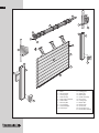
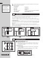
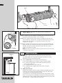
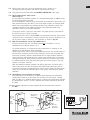
TO SUIT ANSA RS-1 CONTROL
INSTALLATION AND USER MANUAL FOR
IMPORTANT
PLEASE READ THESE INSTRUCTIONS CAREFULLY PRIOR TO
COMMENCING THE INSTALLATION OF THE UNIT
The THERMAGLIDE door has been designed to provide years of trouble free use.
The unit will perform efficiently only if it is installed and operated properly.
READ THESE IMPORTANT SAFETY RULES FIRST
This equipment must be installed and used in accordance with these
instructions. Failure to follow these instructions could result in damage
to the integrity of the safety circuits.
Two persons are required to install this product to ensure safe
handling procedures.
CAUTION
Do not wear rings, watches or loose clothing while installing or servicing
the unit.
To avoid serious personal injury from entanglement, remove any ropes
connected to the equipment prior to operating door.
Installation and wiring must be in accordance with your local building and
electrical regulations.
DANGER Any electrical work must be carried out by a suitably qualified person, if in
doubt consult a qualified electrician.
Use only the mains lead supplied with the operator.
Connect the mains lead to an adjacent 13amp 3 pin switched socket.
The plug must be fitted with a 5 amp fuse.
NOTE: For optimum electrical safety this unit should be connected to
circuit protected by a R.C.D. (max 30 mA trip rating).
This unit should not be installed in a damp or wet space.
Disconnect electric power to the control unit before making repairs or
removing covers.
DANGER
Install the door control box (or any additional push buttons) in a location
where the garage door is visible, but out of the reach of children. Do not allow
CAUTION children to operate push button(s) or remote control(s). Serious personal injury
from a closing garage door may result from misuse of the operator.
CAUTION: Activate unit only when the door is in full view, free of obstructions
and operator is properly adjusted. No one should enter or leave the garage
while the door is in motion. Do not allow children to play near the door.
IMPORTANT: Fix the caution label supplied to the rear of the garage door
as a reminder of safe operating procedures.
CAUTION
Ensure “Beam break” photo-cell is installed and operating correctly.
Once a month check for correct safety operation, (see Section 19)
NOTE TO INSTALLER
PLEASE ENSURE THIS MANUAL REMAINS WITH THE END USER AS
IT CONTAINS IMPORTANT SAFETY AND WARRANTY INFORMATION
2
7
4
6
3
2
5
1
13
12
9
10
15
8
16
14
21
13
17
12
19
18
20
1. Motor
2. Axle assembly
3. Locking rings
4. Shaft end cap
5. Shaft support bracket
6. Guide rollers
7. R/H end plate
8. L/H end plate
9. Overide adapter
10. Overide eye
11. Locking joint
12. Guide rails
13. Brush strips
14. Curtain assembly
15. Door Laths
16. Locking caps
17. Bottom lath
18. Rubber seal
19. Control unit
20. Photo beam unit
21. Photo beam reflector
3
COMPONENT CHECK:
Unpack and check that all components are present.
1
Curtain assembly (inc. set of locking joints)
2
Axle assembly (pre-fitted with motor, locking rings and shaft end cap)
3
1 pair of guide rails (pre-fitted with brush strips)
4
Accessory pack comprising:
1 pair of end plates (pre-fitted with rollers)
1 motor override eye and manual winding handle
1 shaft support bracket
1 fittings pack
5
Control system comprised of:–
– Control unit/radio receiver Pre-wired and temporarily attached
to axle assembly for R.H. Motor installation
– Photo cell unit
as standard
– Mains lead
– Remote hand transmitter
– Photo cell reflector and mounting bracket set
Ñ
1
PRE-INSTALLATION CHECK:
IMPORTANT NOTE
In case of power failure a manual override system is fitted as standard but this
can only be operated from inside the garage.
If the garage has no service entrance door then an EXTERIOR RELEASE KIT
MUST be fitted to allow manual operation of the garage door from outside.
(See back page for order details).
1
2
Check that the door size and colour correspond with that which was ordered.
Structural condition of opening
ENSURE THE AREA AROUND THE OPENING IS STRONG ENOUGH TO SUPPORT
THE DOOR
The surface where the door is to be fitted must be flush and reasonably smooth.
Small irregularities in the brickwork will be acceptable. The lintel must not
protrude backwards or forwards from the brick piers. Should the lintel protrude
backwards or forwards from the brick piers this will require special instructions,
please consult your Thermaglide dealer.
3 Fitting notes
3.1 It is recommended that 2 people are available for fitting all door sizes.
3.2 The door must be fitted square and level, irrespective of the shape of the opening.
On no account should any compensation be made to suit an irregular opening.
3.3 Ensure all necessary tools are to hand before starting.
3.4 The door package and its contents should be checked for obvious damage before
removal of the wrapping.
IF THERE IS ANY DAMAGE YOUR SUPPLIER SHOULD BE CONTACTED
IMMEDIATELY.
4
Ensure there is a suitable 13amp 3 pin switched socket adjacent to where the
control box is to be fitted. (see safety rules)
4
5
Ensure all tools and door components are gathered together inside the garage
prior to starting the installation.
NOTE A: No wall
plugs are provided.
It is the responsibility
of the installer to
provide and fit wall
plugs suitable for the
structure to which the
door is to be fitted.
Tools required:–
2 stepladders
Spirit level
Steel tape
Power drill
10mm A/F spanner
Slot screwdriver
Pozi screwdriver
2
3.8 drill bit
7.0 drill bit
13.0 drill bit
Hacksaw
Suitable wall plugs (not supplied) see note A
Small electrical screwdriver
3mm A/F Allen key
CHECK HEADROOM
The headroom is the clear vertical height required between the top of the guide rails
and any obstruction above the shutter (see Figs 1 and 2).
This space is required to house the door roll and for doors up to 9.0 sq. metres a
headroom of 270mm is required. For doors over 9.0 sq. metres this increases to 300mm.
Limited Head room
If insufficient headroom is available the door can still be fitted (see your survey sheet)
but the shorter guide rails will give a corresponding reduction in door opening height
(see Fig 3).
270
Headroom
Fig 1 Headroom within
aperture
Fig 2 Headroom behind aperture
3
Door open
height
Aperture
height
Aperture
height
270
Headroom
Door open
height
Aperture height
270
Headroom
Total avaible height
NOTE: Ensure that the headroom above the guides is clear of any obstructions
(especially small protrusions or nail heads) which could cause damage to the door roll
during installation/operation.
Fig 3 Limited headroom
PREPARING THE GUIDE RAILS
For fitting WITHIN the aperture.
3.1.1Check guide rail length
Check that guide rails have been supplied to the correct length as
per your survey sheet/order. The correct length is aperture height
less 270mm (see Fig 1).
Drill 13.0
3.1.2Drill fixing holes
Drill holes through 7.0 diameter and counter drill 13.0 diameter
as shown in Fig 4.
Three holes per rail are required, positioned as shown in Fig 5.
NB. Position holes for best fixing to brickwork.
Drill 7.0
Fig 5
Guide Rail Length
150 min.
150 min.
3.1
Fig 4
5
For fitting BEHIND the aperture
Guide rail
height
3.2.1Check guide rail length
Check that guide rails have been supplied to the correct length as per your
survey sheet/order.
a. Where headroom of 270mm or more is available guide rail length equals
aperture height (see Fig 6).
b. Where only limited headroom is available guide rail length equals total
available height less 270mm. (see Fig 7).
Aperture height
3.2
3.2.2Drill fixing holes
Drill holes through 7.0 diameter and counter drill 13.00 diameter as shown in
Fig 8. Three holes per rail are required as shown in Fig 9.
NB position holes for best fixing to brickwork.
Fig 6
Guide Rail Length
150 min
Drill 13.0
15.0
Fig 7
4
150 min
Total available height
Guide rail height
270
Drill 7.0
Fig 8
Fig 9
ASSEMBLE FRAME
4.1 L/H or R/H motor
The motor and control unit can be mounted on either the L/H side or R/H side.
Decide which side is best suited for your installation and proceed accordingly.
(Fig 11 shows assembly for RH motor mounting).
NOTE ALL units are supplied pre-wired for RH motor mounting as standard
(see page 9)
4.2 Fit end plates
Lay the axle assembly on the ground, parallel with and just inside the garage
opening. Ensure the motor is situated at the correct end for your installation
and that the motor limit adjusters are at the top/bottom (see Fig 10).
Fix the end plate to the motor using two M6 x 25 c’sunk screws and M6 Nyloc
nuts provided. See Fig 11.
M6 Nyloc nut
Shaft support
bracket
Shaft
Locking
rings
Adjuster
Axle
Motor
M6x25
c’sunk
screw
Adjuster
End plate
End
plate
Roller
Shaft
support
bracket
Roller
NOTE: R.H. motor mounting shown
Fig 11
Fixing
screws
Limit
adjusters
Manual
winder
must be
at front
Guide
roller
Fig 10
6
Fix the shaft support bracket to the other end plate using 4 off M6 x 25
c’sunk screws and M6 Nyloc nuts provided. Ensure orientation of the
bracket is as shown in Fig 12.
Fix SHAFT to end plate by aligning hole in shaft with hole in ‘U’ bracket and
using the M6 x 35 Hex head bolt and M6 Nyloc nut provided (see Fig 12).
4.3 Fit guide rails
Select R/H guide rail and slide fully onto the bottom square tube spigot projecting
from the R/H end plate. Repeat for the L/H guide rail as shown in Fig 13.
M6
Nyloc nut
Shaft support
bracket
M6x35
Hex.
head
Axle assembly
Fig 12
Left-hand
guide rail
Right-hand
guide rail
Fig 13
5
INSTALL FRAME
You will have drilled your guide rails (Section 3) for fitting either:–
a Within the aperture b Behind the aperture
Please proceed accordingly. (SAFETY NOTE: 2 people required)
5.1 Fitting within aperture
For installation within the aperture we strongly recommend the use of a Fascia
plate as this covers and protects the door curtain roll
5.1.1Fit fascia plate as per the instructions provided with that item.
5.1.2Lift the frame assembly into position and align with the front of the aperture.
Ensure the guide rails are VERTICAL (in both directions) are parallel to each other,
at the same height and the correct distance apart.
NB: Some width adjustment is available on the sliding shaft end of the axle,
the correct distance is shown in Fig 14.
Ensure the axle assembly is horizontal by using a spirit level.
Lath width (excluding end caps)
Lath width +84.0
Fig 14
7
5.1.3Once the frame is correctly positioned, mark and drill for fixings.
Use 3 per side of the No. 12 x 3" self tapping screws provided using suitable wall
plugs (see Note A).
5.1.4When the guide rails are securely fixed, double check that they are vertical,
parallel and correct distance apart and that the axle assembly is level.
5.1.5Fix end plates to the wall by drilling a hole 7.0 diameter through the plate in a
position to suit the brickwork. Drill the brickwork and fix with one No. 12 x 3"
screw (provided) in each end plate (see Note A).
5.2 Fitting behind aperture
Lift the frame assembly into position and align centrally with the aperture. Ensure
the guide rails are vertical (in both directions) and are parallel to each other, at the
same height and the correct distance apart.
NOTE: Some width adjustment is available on the sliding shaft end of the axle.
The correct distance apart is shown in Fig 14.
Ensure axle is horizontal by using a spirit level.
5.2.1Once the frame is correctly positioned, mark and drill for fixings. Use 3 per side of
the No. 12 x 3" self tapping screws provided and suitable wall plugs (see Note A).
5.2.2When guide rails are securely fixed, double check for vertical, parallel and correct
spacing and that the axle is level.
5.2.3Fix end plates to lintel wall by drilling a hole (7.0 diameter) through the square
tube projecting above the end plate, position to suit brickwork.
Drill the brickwork and fix with one No.12 x 3" screw (provided) in each end plate.
NOTE: Once the frame is fully fitted and checked, use the plastic plugs supplied to
cover the fixing holes in the guide rails to give a ‘fully finished’ effect.
6
INSTALLING THE CURTAIN ASSEMBLY
6.1 Carefully unwrap and remove the electrical control system from the axle, where it
is attached only for transportation purposes.
Temporarily secure it to one side, away from the axle and frame assembly.
6.2 Carefully position the curtain assembly in the door aperture, below the axle as
shown in Fig. 15. Slit the packaging to gain access to the curtain but leave some
packaging to protect the curtain.
Axle
Bottom
seal
Bottom
lath
Curtain assembly
Locking
joint
Wrapping
Fig 15
8
Bottom
lath
Curtain
assembly
Fig 16
Bottom
lath
6.3 SAFETY NOTE: Two people are required for this procedure to
ensure safe handling.
6.3.1It is essential to place sections of bubble wrap or card over the axle
to prevent marking the curtain as it is installed.
6.3.2Using 2 people carefully lift the curtain assembly up level with the
axle. Practice has shown that it is best to place one hand on the axle,
keeping that arm straight, and support the curtain roll on that
shoulder (see Fig 16).
Axle
Guide
roller
Guide
rail
6.3.3Feed the bottom lath over the top of the axle and down between the
guide rails (see Fig 17) taking care not to scuff the curtain assembly.
Proceed until the full curtain has been fed over the axle and the
bottom lath reaches the floor.
Curtain
assembly
NOTE: Do not let the curtain ‘free fall’ over the axle as this will result
in damage to the curtain.
Fig 17
7
Adjacent
13A switched
socket
7.1 The electric motor, control box, photo-cell and mains lead are all
pre-wired together and have been temporarily secured to one side.
Release them from this temporary fixing.
Control
box
1.6 m
7.2 Fix the control box to an adjacent wall,ensuring that:–
a. It can be plugged into an adjacent 13amp switched socket.
b. It is within the constraints of the motor to control box lead,
using a ‘tidy’ cable run.
c. It is mounted with the light at the top.
d. It is mounted high enough to be out of reach of children
(see Fig 18).
7.3
Floor
Fig 18
CONNECT THE ELECTRICS
Fitting the enclosure
Remove the courtesy lamp lens from the base by squeezing the side
of the lens and pulling away, disengaging the clip in the top of the
lens. Remove any packaging from the lamp.
Pull off the trim, and undo the two fixing screws approx 8mm, noting
that it is not necessary to completely remove the screws which remain
attached to the cover. Carefully remove the cover by pulling away from
the base with a slightly downward movement.
9
7.4
Mark and drill the wall and fix the control box using 3 off No. 8 x 1”
self tapping screws provided. (see Note A concerning wall plugs)
7.5
Plug power lead into 13A socket but DO NOT SWITCH ON at this stage
7.6
Fit the photo electric safety sensor
Refer to Fig 19
Fix the Photo-Cell Brackets to guides at a recommended height of 300mm using
the self-drilling screws provided.
Fit the photoelectric sensor to the pivot bracket using 2No M3 x 25mm nuts and
bolts provided ensuring that the flat and shake proof washers are correctly fitted.
Attach the pivot bracket to the photocell bracket using 2No M4 x 15mm nuts
and bolts provided.Fit the photocell reflector to the opposite bracket using
2No M4 x 15mm nuts and bolts provided.
The diagram shows a right hand installation. The photo sensor can be fitted to
the left hand using a similar assembly.
Ensure power to the unit is switched OFF and secure the photo cell sensor cable
using cable clips [ not supplied ] leaving sufficient slack for final adjustment. Cut
off any excess cable, if necessary, and re-connect as shown in Fig 20.
7.7
Align the photoelectric sensor [ Type MLV 13/54 ]
Fit cover to the control unit and switch power ON. [ The Green L.E.D. on
photoelectric cell indicates power is on ].
For reliable operation it is important that the photo beam is “centred” on the
reflector using the following set-up procedure:
Adjust fixing screws A & B so that the photoelectric sensor and pivot bracket can
be moved up and down and left to right. Move the sensor until the yellow LED
illuminates. Carefully move the pivot bracket left and right to obtain reference
points where the yellow LED goes out. Set the pivot bracket in the mid position
and tighten screws A. Now similarly move the sensor up and down again noting
the reference points where the yellow LED goes out. Set the sensor in the mid
position and tighten screws B
With the photocell correctly adjusted and working the green and yellow LED’s
fitted to the sensor and the red indicator LED fitted to the control unit will be
illuminated. Breaking the photo-beam will switch off the yellow LED fitted to the
sensor and cause the red indicator LED to flash quickly, confirming the correct
operation.
7.8
Photoelectric sensor operation and testing
The safety beam has no effect on an opening door. Breaking the safety beam
prevents the closure of an open door and will stop and also re-open a closing
door. The ADS v1.1 software fitted to the RS 1 control unit continuously monitors
the photoelectric sensor. If a fault is detected the system prohibits the closure of
the door.
7.9 Once correct alignment has been established turn the power to the control
box OFF.
“A”
M4 x 15
nuts and bolts
M4 x 15
nuts and
bolts
M3 nuts and
shakeproof
washers
Self
drilling
screws
Photo
cell
bracket
“B”
M3 x 25
bolts and
flat washers
Reflector
PHOTOCELLS
VE
+
Link
Brown
Black
Blue
Fig 20
VE S1 S2 +VE
Photoelectric
sensor
PHOTOCELLS
VE S1 S2
PHOTOCELLS
VE S1 S2
VE
+
Fig 19
10
8
ATTACH THE CURTAIN
8.1 FIT THE MOTOR
OVERRIDE
Attach the motor override
EYE fitting to the motor as
shown in Fig 22. Using
3mm A/F Allen key.
Fig 22
8.2 POSITION THE AXLE
Use the motor override to
rotate the axle shaft.
Rotate the axle until the
locking joint attachment
holes are positioned as
shown in Fig 23.
Locking joint
attachment holes
Forward
8.3 There are a pair of locking
rings positioned on the
shaft for each locking
joint, the number of
locking rings will vary
according to curtain width.
Clamp the outermost rings
to the shaft approx.
150mm in from each end
and equally space the
other pairs as shown in
fig. 24.
Slide each locking joint
along the top lath and
engage the fastening pin
into the appropriate hole
in the respective clamped
locking ring. (Four holes
are provided in the rings
so that shaft position is
not critical).
Slide the loose locking ring
to engage the other end of
the fastening pin and
secure the loose locking
ring to the shaft using the
clamping screw. Repeat
this for each locking joint.
(see Fig 24).
Locking ring
Axle
Fig 23
Slide loose locking ring
to engage pin on locking
joint, then clamp
Top lath partially
engaged in
guide rail
Fig 24
clamped locking
ring
11
9
SETTING CURTAIN OPEN AND CLOSE POSITION
9.1 SETTING OPEN POSITION
L. H. Mounted motor
R. H. Mounted motor
9.1.1Ensure power is turned OFF.
viewed
from
below
viewed from above
9.1.2Remove the protective cap from the head of
the motor. (see Fig 25)
Guide rail
9.1.3Fully depress both limit switch buttons.
override
handle
(see Fig 25). They will automatically lock in
the down position.
CLOSE
9.1.4Turn power ON and operate the START
CLOSE
WHITE
button. Ensure the curtain is moving in the
YELLOW
limit switch
OPEN direction. IF THIS IS NOT CORRECT
limit switch
STOP IMMEDIATELY. Switch off power and
OPEN
interchange the motor wires at terminals L1,
OPEN
YELLOW
WHITE limit
L2 (see Fig 30). Switch power back on and
limit switch
switch
operate start button again, curtain should move
in correct OPEN direction.
9.1.5Identify the OPEN limit switch button on the
override
motor (see Fig 25 for RH or LH mounted motor).
handle
9.1.6When the curtain approaches the fully open
position operate the STOP button to hold the
Guide rail
curtain in position.
Fig 25
9.1.7Use the Motor override handle to move the curtain to the correct OPEN
position.
IMPORTANT see Fig 26 for correct OPEN position.
9.1.8Set the OPEN limit switch by depressing and releasing the limit switch button.
9.2 SETTING CLOSE POSITION
9.2.1Press the START button so curtain moves downwards.
9.2.2Identify the CLOSE limit switch on the motor (see Fig 25).
9.2.3When the curtain approaches the fully closed position operate the STOP button.
9.2.4Use the Motor override handle to move the curtain to the correct CLOSED position.
IMPORTANT see Fig 27 and Fig 28 in section 10 for correct CLOSE position.
9.2.5Set the CLOSE limit switch by depressing and releasing the limit switch button.
9.3 CHECK SETTINGS
Operate the door a number of times to ensure the limits are correctly set. In particular
the CLOSED ‘LOCKED’ position (section 10).
9.4 Reset the protective cap on the limit switches.
(Take care not to depress the limit switch buttons.)
Appropriate
hole in
locking ring
selected
Locking
joint
50 mm
Bottom lath
engaged in
track
Ground level
open position
Fig 26 Fully open Fully
position
Fig 27 Fully closed position
Bottom lath
contacting
ground
12
10
SETTING THE ‘LOCKED’ POSITION
In order that the locking
joints operate effectively,
the position of the shaft in
the closed position needs
to be finely adjusted.
Use the Manual override
to move the curtain
downwards until the
bottom lath is pushed
firmly on the ground and
the top lath is pushed
hard against the head.
The locking joints should
be sprung into the locked
position. (Fig 28). Do not
adjust past this position
as this will impose
excessive loads on the
mechanism.
Locking
Locking
joint
Top lath pushed
against head by
locking joints
Locking joints must be
in ‘locked’ position
(see section 10
Bottom lath
hard on ground
Ground level
Fig 28
11
ELECTRICAL CONTROL CIRCUIT DIAGRAM
Control fuse
T500 MA
Motor run
timer
Open &
close
status
LED’s
Option
DIP
switches
Motor
fuse
T6.3A
De-code
LED
[ Power terminals ]
Fig 29 Control unit PCB layout
[ Control terminals ]
13
IMPORTANT
ALL UNITS ARE PRE-WIRED FOR R.H. MOTOR INSTALLATION. IF YOUR
UNIT IS TO BE INSTALLED FOR L.H. MOTOR OPERATION THEN THE
MOTOR WIRES WILL HAVE TO BE REVERSED AS SHOWN IN FIG ‘30’
NB: WITH A LEFT HAND MOTOR THE PHOTOELECTRIC CELLS AND THE
BRACKETS NEED TO BE REVERSED AS WELL
(SEE ALSO MAIN ELECTRICAL DIAGRAM FIG 29)
SWITCH OFF AT MAINS IF WIRES NEED CHANGING.
MOTOR
E
L1 L2 N3
MOTOR
E
L1 L2 N3
Blue
Brown
Black
Green/Yellow
Green/Yellow
Brown
Black
Blue
LH Mounted Motor
RH Mounted Motor
Fig 30
12
OPERATION
12.1 The microprocessor control unit operates in sequential impulse logic. The door
can be operated using the start button fitted to the front of the control unit, the
remote control hand set or other optional controls connected to the system.
Push any of the above buttons and the door will open. Push a button again and
the door will close. If a button is pressed whilst the door is moving it will stop
and pushing the button again will reverse the original direction.
The advanced electronics monitors the motor drive and limit switches and turn
off the motor run timer as soon as the door reaches a fully open or fully closed
position. There is no need to wait for the run time to expire before closing a
recently opened door and accidentally operating the photoelectric safety sensor
will not affect a recently closed door.
12.2 Function of red LED indicator (see Fig 31)
Operation
Continuous on - Power is switched on [ stand-by mode ]
Flashing quickly - Safety input is active [ e.g. photobeam is obstructed ]
Flashing slowly - Diagnostic self-test is active [ indicates fault in control
wiring, control device or photo-electric sensor. ] Door is inoperable until
the fault is corrected.
12.3 Courtesy lamp
The courtesy light will switch on for four minutes whenever the door is operated
and turn off automatically.
13
13
ADDING TRANSMITTERS
Press the start button for 5 seconds and release when the red LED indicator
goes out. The LED will flash once to confirm the Add Mode.
Take the new transmitter to be added and press the button once. The red
LED indicator should flash once. Repeat this for every new transmitter to be
added to the system.
After the last transmitter has been added either wait 30 seconds or press the
start push button once to reset to normal operation.
The remote control system uses the latest “rolling code” technology. Hand
transmitters supplied are pre-programmed. The receiver can memorise the
codes of 15 transmitters.
Multi-function
Red Indicator LED
Operating Button
Fig 31
14
14
DELETING TRANSMITTERS
It is not possible to selectively delete transmitters and selecting delete mode will
erase ALL transmitters from the system.
Switch off the power supply to the unit and remove the front cover. Turn on Dip
switch 5 and re-power the unit. The circuit board mounted yellow “set radio”
LED will illuminate for 5 seconds, all transmitters are now deleted. Switch off
the power supply, turn off Dip switch 5 and re-fit the front cover. Transmitters
can now be reloaded using the “Add transmitters” procedure.
15
DIP SWITCH SETTINGS
The RS 1 control unit has three onboard Dip switches which control the
following features.
15.1 DIP SWITCH 1 - WARNING
When switched on the courtesy light will flash three times before the door
moves.
15.2 DIP SWITCH 2 - PARTIAL RETRACT
When switched on selects partial retract. If the photocell is activated the door
retracts 200mm instead of returning to the fully open position.
15.3 DIP SWITCH 5 - DECODE
Used when removing lost or stolen transmitters from the receiver memory.
[ see 14 Deleting Transmitters. ]
16
MULTI DOOR CONTROL
Two types of transmitters are available, 1 or 2 buttons, therefore up to two doors
each fitted with a standard RS 1 control unit can be controlled independently by
using a single transmitter. Simply select the transmitter button you wish to use
with a particular door and programme the transmitter as per Section 13
“Adding Transmitters”.
17
PHOTOELECTRIC CELL OVERRIDE
Activation of the safety circuit is indicated by the red LED which will flash
quickly, this could be due to:A loose or poor connection to the terminals -Ve, +Ve, S1 or S2.
A dirty photocell sensor lens or reflector.
Poor alignment of the photoelectric sensor and reflector.
If the safety input is active, the system automatically switches to “Photoelectric
Cell Override Mode” which enables controlled closure of the door in “dead-man”
operation. Using a hand transmitter or the built-on start button and with the door
in full view, press and continue to hold the button. The red LED indicator will
change state from flashing to on. The button is monitored and after 5 seconds
the door will close in “deadman” control. Releasing the button will stop the door
and the above procedure can be repeated to continue closing the door.
18
FAULT DIAGNOSTIC SYSTEM
The microprocessor monitors the circuit board. low voltage wiring, control devices
connected to the system and photoelectric sensor[s] and detects possible faults. If a
fault is detected the door cannot be operated and the red LED will flash slowly. The
power supply should be switched off until the fault is found and corrected.
15
19
SAFETY REVERSE CHECK
Once a month check the SAFETY REVERSE for correct operation.
Using the handset or STOP/START button on the control box operate the door to the fully
open position.
CHECK SAFETY REVERSE
Standing inside the garage operate the door to CLOSE and, whilst it is closing,
block the photo beam (using a piece of cardboard or similar).
The door should immediately stop and then reverse to the fully open position.
IMPORTANT
THE SAFETY REVERSE MUST ONLY OPERATE WHEN THE DOOR IS CLOSING, WHEN THE
DOOR IS OPENING BLOCKING THE PHOTO BEAM SHOULD NOT AFFECT DOOR TRAVEL.
20
PROBLEM SOLVING
20.1 UNIT FAILS TO OPERATE WHEN MAINS POWER SWITCHED ON.
– Try to operate from the handset and from the start button on the control unit.
– See if the courtesy light comes on.
– If unit is ‘dead’ then turn off mains power:
1) Check fuse in 13A plug (should be fitted with 5A fuse)
2) Check fuses in control box (see Fig 29)
CONTROL FUSE
T500mA L 250V dia 5 x 20
MOTOR FUSE
T6.3A L 250V dia 5 x 20
20.2 DOOR NOT FULLY CLOSING TO THE ‘LOCKED’ POSITION
– Adjust the CLOSE limit switch (see Section 9.2).
20.3 DOOR NOT FULLY OPENING
– Adjust the OPEN limit switch (see Section 9.1).
20.4 DOOR WILL OPEN BUT WILL NOT CLOSE
– Check alignment of the photo beam (see Section 7.7).
– Check electrical connections of the photo cells.
20.5 DOOR TIGHT OR JAMS IN OPERATION
– Check for good entry of curtain laths into guide rails .
– Check that bottom lath is correctly engaged into track when fully open
(see Section 9.1).
– Check for correct clearance of curtain in guide rails. NB: laths should have a
sideways ‘end float’ of approx 6mm.
– Adjust guide rails if necessary to achieve free movement.
20.6 DOOR WILL NOT OPERATE FROM REMOTE CONTROL HANDSET
– Check that door operates correctly from the start button on the control unit,
to prove system function.
– Check that signal is being sent from the handset. Red LED should illuminate
on the handset when button is pressed.
IF NOT – replace battery in handset.
– Reset the code (see Section 14)
– Fit optional aerial
FIT THE OPTIONAL AERIAL
The circuit board incorporates a built on aerial for the remote control receiver which
is ideal for most applications.
An optional aerial is supplied which can be fitted as follows:
Pass the 135mm stainless steel wire aerial through the small hole in the base of the
RS 1 control unit and connect to the terminal marked “EXT A”. Snip the wire link
marked “A” on the circuit board, this is located on the right hand side of the board
just above the receiver card.
IMPORTANT
THE MOTOR IS FITTED WITH A SAFETY THERMAL CUT OUT. IF THE UNIT IS OPERATED
MORE THAN 5–6 TIMES THE CUT OUT WILL BE ACTIVATED AND SHUT THE UNIT DOWN.
ALLOW 15–20 MINUTES FOR MOTOR TO COOL DOWN.
21
OPERATING INSTRUCTIONS
21.1 General operation
Your THERMAGLIDE door can be operated from outside or inside the garage
using the Remote Control Handset, or from inside the garage using the START
BUTTON mounted on the Control Box.
CAUTION: Activate unit only when the door is in full view, free of obstructions and
operator is properly adjusted. No one should enter or leave the garage while the
door is in motion. Do not allow children to play near the door.
21.2 In event of power failure
If the door is not used during the power failure then no action has to be taken as
the unit will reset itself when the power is restored.
If required the door can be operated manually by using the winding handle supplied,
for which you have to gain access to the inside of the garage.
Insert the hooked end of the winding handle into the override eye, this is
projecting downwards from the drive motor at one end of the curtain roll.
(see Section 8). Rotate the handle to operate the door to open or close.
IMPORTANT If the garage has no service door then an EXTERIOR RELEASE KIT
should have been fitted to allow EMERGENCY opening from outside.Follow
instructions supplied with that kit.
NOTE: When closing the door manually ensure that the locking joints are set
in the fully closed position to ensure security (see Fig. 28).
22
MAINTENANCE
The Thermaglide door is essentially a low maintenance product but certain simple
checks, carried out regularly, will ensure extended trouble free operation.
CLEANING
– Periodically wash the door curtain with warm soapy water using a soft cloth.
– Check and clean out the guide rails, removing any accumulated leaves and debris.
– Ensure door closes onto a level clean surface.
– Clean photocell lens and reflector using damp soft cloth.
SAFETY
Regularly check the safety reverse photo beam for correct operation (see Section 19).
23
ACCESSORIES
The following accessories are available for use with your THERMAGLIDE door:AZAT 0006 – Additional hand transmitters (1 channel)
AZAT 0007 – 2 channel hand transmitter
AZAT 0008 – 3 channel hand transmitter
AZAT 0003 – Up/down switch
AZAT
AZAT
* AZAT
* AZAT
0004 – Touch up paint ALL COLOURS
0005 – Exterior release kit
0050 – Fascia plate WHITE/BROWN/BEIGE cut to your required length.
0051 – Vision panel
*Only available when ordered with door.
IN THE EVENT OF DIFFICULTY PLEASE CONSULT YOUR THERMAGLIDE
INSTALLER OR CONTACT:
THERMAGLIDE TEL: 01724 270396
DPIN 8091 ISSUE D FEBRUARY 2004