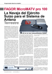
Download The Microma-MATV Aerial System Test Report (400kb pdf)
Transcript
TEST REPORT
Programmable Selective Amplifier
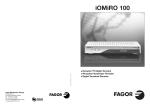
FAGOR MicroMATV pro 100
Swiss Army Knife
for the Terrestrial
Antenna System
When writing about antenna systems here in TELE-satelite, we usually mean the satellite
antenna systems. However, most of us who use the satellite receivers do not resign from the
conventional terrestrial reception. After all, quite often an interesting channel is transmitted
for free in your region via the terrestrial transmitter. This channel may be not available through
satellite (for example local news channel) or be a part of a Pay-TV satellite package. New digital
channels show up in the terrestrial TV what keeps it attractive.
Depending on the region you live, you can
receive the terrestrial channels with either
a single dipole/yagi antenna or you have to
install a number of them pointing in different directions. In the latter case, it is always
necessary to combine the signals from a few
antennae into one signal and send it down to
the TV-set. In the family house, such signal
is usually distributed among many rooms. In
the block of apartments – among many flats.
Combining the signal from different antennae was usually done with a mixture of amplifiers, multiplexers and filters (or traps). For a
regular mortal, it was a kind of black magic
what kind of equipment should he or she use
and how to interconnect all components. This
kind of problem does not exist when you have
a selective programmable amplifier from
Spanish company Fagor Electronica.
The first products from that company
appeared on the market already in 1992. The
products offered now belong to the third generation. Fagor Electronica designed and produced a family of products called MicroMATV
pro, models: 100, 100C, 200C and 300C. They
differ in number of inputs and Automatic Gain
Control function. To put it simply, a selective
programmable amplifier enables us to connect a several antennae to one TV-set or to
one distribution cable network.
We took a closer look at the MicroMATV
pro 100 model. You can connect up to six different antennae for various bands. You have
the following inputs: FM (87.5-108 MHz0, BI
(47-68 MHz), BIII/DAB (174-230 MHz) and 3
UHF inputs (470-862 MHz). Unfortunately the
model we tested had no SAT IF input (9502150 MHz). This input is available in models
200C and 300C. However, it had an auxiliary input AUX (47-68, 130-862 MHz). Using
this input and the additional device of Fagor
Electronica called DISAT-4, you can connect
a satellite dish to the system. Alternatively,
the AUX input may be used for some other
TV or radio signal (for example from another
MicroMATV amplifier output or from an existing cable TV network).
Programmable Selective Amplifier TEST REPORT
Figure 1 shows the exemplary antenna
system that Fagor Electronica provide in
their user manual. Not only can you connect a number of antennae to the amplifier
but also you have the possibility to adjust
its amplification for different inputs. And
that’s not all. In the UHF bands, you can set
a number of filters so that to pass only a portion of the UHF frequency spectrum: 470-862
MHz. In this way, you filter out the part of
band in which the TV channels that you want
to receive are transmitted.
For example: you may take channels
settings and a power cord for 230Vac supply.
The unit itself is rather big and heavy and it is
designed to be wall mounted in the indoors. It
makes an impression of a very solid piece of
equipment. Its workmanship leaves nothing
to be desired. The user manual that we got
along with the unit was prepared in Spanish,
French and English. Apart from the specifications, it includes the programming guide.
At first we were somewhat afraid that it
may be not that easy to enter all the necessary settings, but the reality was quite the
Fig. 1. Exemplary antenna system
We started with FM band. As you can see
in figure 2, the filter amplitude response is
practically perfect. No passband ripple, and
very steep rolloff of 25dB/8MHz. Filter covers
exactly 87.5-108 MHz band. [Fig. 2.]
The gain can be adjusted in 25 steps.
According to the specification, the adjustment range should be 25 dB. We measured
that actually the range is somewhat bigger:
28 dB. One step is roughly 1 dB.
The difference between specification and
actual adjustment range was even bigger
in BI band (47-68 MHz). Instead of 25 dB
adjustment range, the actual range was
35 dB. So, we got something between 1.5
and 1.7 dB per one step. While in practice,
greater range and coarser resolution of
the gain adjustment should not pose any
problem, it is still a certain deviation from
the published specification. The frequency
response for this input was as perfect as for
the FM input. Rolloff was about 20dB/8MHz.
See figure 3. [Fig. 3.]
BIII input (174-230 MHz) was better with
respect to gain setting. For settings between
0 through 20 the actual changes were almost
exactly 1 dB per step. For settings between
20 and 25 it was about 1.5 dB per step. Low
ripple in the passband – see figure 4 but the
rolloff of 10dB/8MHz was not equally good as
for the previous inputs. [Fig.4.]
20-25, 36-37 and 55-60 from the first UHF
antenna, channels 40-42 and 63-65 from
the second UHF antenna and channels 29-32
from the third UHF antenna. You may set up
to 10 different filters in UHF band. The filter’s
pass-through bandwidth can be individually
set from a single channel (8 MHz) to six channel (48 MHz).
opposite. The control unit with 2 line liquid
crystal display and five buttons could not be
simpler to operate! It takes rather seconds
than minutes to understand its logic.
MicroMATV pro 100 comes with an external control unit used to enter all necessary
For our tests, we used the NG-281 noise
generator and the Prolink-4C Premium spectrum analyzer of PROMAX. Additionally, we
checked the operation of the amplifier with
the real TV and radio signals of different frequencies.
Fig. 2. FM input frequency response
Fig. 3. BI input frequency response
Before dealing with the UHF bands, we
quickly checked the auxiliary input (47-68,
130-862 MHz). The flatness of its frequency
characteristics was a nice surprise – see
figure 5. You should take into account that
our noise generator had ca. 5 dB decrease
in amplitude at maximum frequency. So the
amplifier itself introduce maybe 1 or 2 dB
difference in amplitude response over the
entire band! [Fig. 5.]
When we moved to the most interesting
inputs – UHF inputs, the first observation was
Fig.4. BIII/DAB frequency response
TEST REPORT Programmable Selective Amplifier
that the rolloff of the filter is slightly worse
compared to the previous fixed band inputs.
Although we got quite good 17dB/8MHz for
the lower slope but only 9dB/8MHz for the
upper slope of the filter. When the filter was
set to one or two channel bandwidth, its frequency response looked quite good, but for
the wider settings we observed a dip between
2 peaks in the passband. Figure 6 shows a
filter set for 1 channel and figure 7 shows
filter set for 6 channels. [Fig. 6.] [Fig. 7.]
Fig. 5. Auxiliary input frequency
response
Still more passband ripple resulted when
we tried to achieve more than 6-channel wide
bandwidth by setting 2 adjoining filters on one
UHF input. We set the first filter for channels
21-26 (474-514 MHz) and the second filter
for channels 27-32 (522-562 MHz). In such
configuration, one could expect a frequency
response more or less flat for channels 2132 (474-562 MHz). As you can see in figure
8, the frequency response was not perfectly
flat. It had peaks and dips. Of course, this
will result in lower and higher amplification
of different TV channels. Fortunately, the difference was not great and it should not pose
any problem for the TV-set to cope with such
differences. [Fig. 8.]
The gain setting for the UHF bands turned
out to be very linear. Every 5 step setting
change resulted in almost exactly 5 dB
change of the amplifier output. Apart from
the frequency response and gain setting, we
took a several measurements of signal to
noise. All of them showed almost no degradation of S/N ratio between amplifier output
and input. MicroMATV pro 100 is really a low
+
noise amplifier! Also, all the practical tests
with live TV signals showed absolutely no distortion or noise in the output of the device.
The MicroMATV pro programmable selective amplifiers have other practical features
like Automatic Equalization System or Automatic Gain Control. AES when activated,
measures the signal at all inputs and automatically sets the optimum gain setting for
every band. This is extremely convenient!
Without this feature, the installer should
either use something like spectrum analyzer
to check the output level for every channel or
group of channels or do it by trial and error.
AGC helps keeping the optimal output level
when incoming signal changes in power, for
example due to weather conditions.
The amplifiers can automatically recognize
the digital channels and keep their level 15
dB below the analog channel level. Thanks
to this, DVB-T receivers or digital/analog
TV-sets work properly. We can say that
Fagor’s selective amplifiers are really ready
for today’s mixed analog/digital terrestrial
transmissions.
Expert conclusion
Very versatile, replaces big number of classical devices like amplifiers, filters or multiplexers. Easy programming. AES function makes
the necessary adjustments very simple. Low noise. Flat frequency
response of the AUX amplifier.
-
Fig. 6. UHF filter set to one channel
bandwidth
Different sensitivity of gain setting (dB per step) on various bands.
The rolloff of the upper slope of UHF filters could be steeper.
Peter Miller
TELE-satellite
Test Center
Poland
TECHNICAL
DATA
Fig. 7. UHF filter set to six channel
bandwidth
Fig. 8. Interaction between two adjoining 6-channel wide filters
Manufacturer
Fagor Electronica, S.Coop., San Andres,
Mondragon, Spain
www.fagorelectronica.es
E-mail
[email protected]
Phone
+34 43 712526
Fax
+34 43 712893
Model
MicroMATV pro 100
Description
Programmable Selective Amplifier
Inputs
FM, BI, BIII/DAB, AUX, 3xUHF
Number of programmable
amplifiers/filters in UHF band
10
Programmable filter bandwidth
8 - 48 MHz (1-6 channels)
Maximum gain
23-53 dB (depending on band)
Input adjustment
23-25 dB (depending on band)
Output adjustment
20-25 dB (depending on band)
Noise factor
6-8 dB (depending on band)
Output level
116 dBµV (DIM –35dBc) for FM
121 dBµV (DIM –60dBc) for other bands
Power supply
230 Vac ±15%
Ambient temperature
0-50ºC


