1
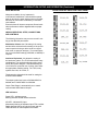
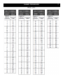
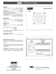
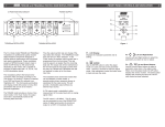
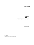
QM1000
QAM MODULATOR with UPCONVERTER
INSTRUCTION MANUAL
Is a registered trademark of the R.L. Drake Company
© Copyright 2014 R. L. Drake Holdings, LLC
P/N: 651227800A
Rev: 100814
1002572
CAUTION STATEMENTS
WARNING: TO PREVENT FIRE OR
ELECTRICAL SHOCK, DO NOT
EXPOSE TO RAIN OR MOISTURE
2
A product and cart combination should be
moved with care. Quick stops, excessive
force and uneven surfaces may cause the
product and cart combination to overturn.
The lightning flash with arrow head
symbol, within an equilateral triangle, is
intended to alert the user to the presence of
uninsulated "dangerous voltage" within the
product's enclosure that may be of sufficient
magnitude to constitute a risk of electric
shock to persons.
The exclamation point within an equilateral
triangle is intended to alert the user to
the presence of important operating and
maintenance (servicing) instructions in the
literature accompanying the product.
***NOTE: Connect and apply power only after all other connections are made.***
IMPORTANT SAFETY INSTRUCTIONS
WARNING:
O REDUCE THE RISK OF FIRE OR ELECTRIC SHOCK, DO NOT EXPOSE THIS PRODUCT TO
T
RAIN OR MOISTURE.
DO NOT OPEN THE CABINET, REFER SERVICING TO QUALIFIED PERSONNEL ONLY.
CAUTION:
T
O PREVENT ELECTRIC SHOCK, DO NOT USE THIS (POLARIZED) PLUG WITH AN EXTENSION
CORD RECEPTACLE OR OTHER OUTLET UNLESS THE BLADES CAN BE FULLY INSERTED TO
PREVENT BLADE EXPOSURE.
ATTENTION: POUR PREVENIR LES CHOCS ELECTRIQUES, NE PAS UTILISER CETTE FICHE POLARISEE
AVEC UN PROLONGATEUR, UNE PRISE DE COURANT OU UNE AUTRE SORTIE DE COURANT,
SAUF SI LES LAMES PEUVENT ETRE INSEREES A FOND SANS EN LAISSER AUCUNE PARTIE A
DECOUVERT.
1.
Read Instructions: All the safety and operating instructions should be read before the product is operated.
2.
Retain Instructions: The safety and operating instructions should be retained for future reference.
3.
Heed Warnings: All warnings on the product and in the operating instructions should be adhered to.
4.
Follow Instructions: All operating and use instructions should be followed.
5.
Cleaning: Unplug this product from the wall outlet before cleaning. Do not use liquid cleaners or aerosol cleansers. Use a damp cloth
for cleaning.
6.
Attachments: Do not use attachments that are not recommended by the product manufacturer as they may cause hazards.
7.
Water and Moisture: Do not use this product near water—for example, near a bathtub, wash bowl, kitchen sink or laundry tub; in a
wet basement; or near a swimming pool; and the like.
8.
Accessories: Do not place this product on an unstable cart, stand, tripod, bracket, or table. The product may fall, causing serious
injury to a child or adult, and serious damage to the product. Use only with a cart, stand, tripod, bracket, or table recommended by
the manufacturer, or sold with the product. Any mounting of the product should follow the manufacturer’s instructions, and should use
a mounting accessory recommended by the manufacturer.
9. A product and cart combination should be moved with care. Quick stops, excessive force, and uneven surfaces may cause the product
and cart combination to overturn.
10. Ventilation: Slots and openings in the cabinet are provided for ventilation and to ensure reliable operation of the product and to
protect it from overheating, and these openings must not be blocked or covered. The openings should never be blocked by placing
the product on a bed, sofa, rug, or similar surface. This product should not be placed in a built-in installation such as bookcase or rack
unless proper ventilation is provided or the manufacturer’s instructions have been adhered to.
IMPORTANT SAFETY INSTRUCTIONS (Cont.)
3
3
11. Power Sources: This product should be operated only from the type of power source indicated on the marking label. If you are
not sure of the type of power supplied to your home, consult your product dealer or local power company. For products intended to
operate from battery power, or other sources, refer to the operating instructions.
12. Grounding or Polarization: This product may be equipped with a polarized alternating-current line plug (a plug having one blade
wider than the other). This plug will fit into the power outlet only one way. This is a safety feature. If you are unable to insert the plug
fully into the outlet, try reversing the plug. If the plug should still fail to fit, contact your electrician to replace your obsolete outlet. Do
not defeat the safety purpose of the polarized plug. Alternate Warnings – If this product is equipped with a three-wire grounding- type
plug, a plug having a third (grounding) pin, the plug will only fit into a grounding-type power outlet. This is a safety feature. If you are
unable to insert the plug into the outlet, contact your electrician to replace your obsolete outlet. Do not defeat the safety purpose of
the grounding-type plug.
13. Outdoor Antenna Grounding: If an outside antenna or cable system is connected to the product, be sure the antenna or
cable system is grounded so as to provide some protection against voltage surges and built-up static charges. Article
810 of the National Electrical Code, ANSI/NFPA 70, provides information with regard to proper grounding of the mast and
supporting structure, grounding of the lead-in wire to an antenna discharge unit, size of grounding conductors, location of
antenna-discharge unit, connection to grounding electrodes, and requirements for the grounding electrode.
Power-Cord Protection: Power-supply cords should be routed so that they are not likely to be walked on or pinched by items placed
14. upon or against them, paying particular attention to cords at plugs, convenience receptacles, and the point where they exit from the
product.
15. Lightning: For added protection for this product during a lightning storm, or when it is left unattended and unused for long periods
of time, unplug it from the wall outlet and disconnect the antenna or cable system. This will prevent damage to the product due to
lightning and power-line surges.
Power Lines: An outside antenna system should not be located in the vicinity of overhead power lines, other electric light or power
16. circuits, where it can fall into such power lines or circuits. When installing an outside antenna system, extreme care should be taken
to keep from touching such power lines or circuits as contact with them may be fatal.
17. Overloading: Do not overload wall outlets, extension cords, or integral convenience receptacles as this can result in a risk of fire or
electric shock.
18. Object and Liquid Entry: Never push objects of any kind into this product through openings as they may touch dangerous voltage
points or short-out parts that could result in a fire or electric shock. Never spill liquid of any kind on the product.
19. Servicing: Do not attempt to service this product yourself as opening or removing covers may expose you to dangerous voltage or
other hazards. Refer all servicing to qualified service personnel.
20. Damage Requiring Service: Unplug this product from the wall outlet and refer servicing to qualified service personnel under the
following conditions:
a) When the power-supply cord or plug is damaged,
b) If liquid has been spilled, or objects have fallen into the product,
c) If the product has been exposed to rain or water,
d) If the product does not operate normally by following the operating instructions.
Adjust only those controls that are covered by the operating instructions as an improper adjustment of other controls may result in
damage and will often require extensive work by a qualified technician to restore the product to its normal operation, e. If the product
has been dropped or damaged in any way, and f. When the product exhibits a distinct change in performance—this indicates a need
for service.
21. Replacement Parts: When replacement parts are required, be sure the service technician has used replacement parts specified by
the manufacturer or have the same characteristics as the original part. Unauthorized substitutes may result in fire, electric shock or
other hazards.
22. Safety Check: Upon completion of any service or repairs to this product, ask the service technician to perform safety checks to
determine that the product is in proper operating condition.
23. Wall or Ceiling Mounting: The product should be mounted to a wall or ceiling only as recommended by the manufacturer.
24. Heat: The product should be situated away from heat sources such as radiators, heat registers, stoves, or other products (including
amplifiers) that produce heat.
WARRANTY STATEMENT
4
THREE YEAR LIMITED WARRANTY
R.L. DRAKE LLC warrants to the original purchaser this product shall be free from defects in material or workmanship for
three (3) years from the date of original purchase.
During the warranty period the R.L. DRAKE LLC or an authorized Drake service facility will provide, free of charge, both
parts and labor necessary to correct defects in material and workmanship. At its option, R.L. DRAKE LLC may replace a
defective unit.
To obtain such a warranty service, the original purchaser must:
(1) Retain invoice or original proof of purchase to establish the start of the warranty period.
(2) Notify the R.L. DRAKE LLC or the nearest authorized service facility, as soon as possible after discovery of a
possible defect, of:
(a) the model and serial number,
(b) the identity of the seller and the approximate date of purchase; and
(c) A detailed description of the problem, including details on the electrical connection to associated
equipment and the list of such equipment.
(3) Deliver the product to the R.L. DRAKE LLC or the nearest authorized service facility, or ship the same in its
original container or equivalent, fully insured and shipping charges prepaid.
Correct maintenance, repair, and use are important to obtain proper performance from this product. Therefore carefully
read the Instruction Manual. This warranty does not apply to any defect that R.L. DRAKE LLC determines is due to:
(1) Improper maintenance or repair, including the installation of parts or accessories that do not conform to the
quality and specifications of the original parts.
(2) Misuse, abuse, neglect or improper installation.
(3) Accidental or intentional damage.
All implied warranties, if any, including warranties of merchantability and fitness for a particular purpose, terminate three
(3) years from the date of the original purchase.
The foregoing constitutes R.L. DRAKE LLC's entire obligation with respect to this product, and the original purchaser shall
have no other remedy and no claim for incidental or consequential damages, losses or expenses. Some states do not
allow limitations on how long an implied warranty lasts or do not allow the exclusions or limitation of incidental or consequential damages, so the above limitation and exclusion may not apply to you.
This warranty gives you specific legal rights and you may also have other rights which vary from state to state.
This warranty shall be construed under the laws of Ohio.
For Service, contact:
R. L. DRAKE HOLDINGS LLC
710 Pleasant Valley Drive
Springboro, OH 45066
Customer Service and Parts:
Fax:
Email:
Web Site: (937) 746-6990
(937) 806-1576
[email protected]
www.rldrake.com
INTRODUCTION, SETUP, AND OPERATION
Introduction
The Drake® QM1000 QAM Modulator with
Upconverter is a professional quality modular digital headend component designed to
provide optimum performance with minimized
rack space requirements. This modulator
accepts a MPEG2 transport stream input in an
ASI serial format and is capable of providing
a QAM output with 64 or 256 constellation
points.
FRONT VIEW
Power LED
ASI LED
The modulator performs the forward error
correction (FEC) encoding according to ITU
Channel Selector
J.83 Annex B. Annex B is referred to as
(push wheel)
‘DigiCipher II®’. The front panel push wheel
selector and channel display allow the selection of QAM RF Channel Output, and a
Modulation Selector
sliding Modulation Selector allows for setting
the QM1000’s QAM Output modulation mode
(a CW output mode option is also selectable
to allow measurement of the output level with
an analog signal meter). The output symbol
RF Output Level
rate is set at 5.056941MS/S for 64QAM, and
Adjustment Dial
5.360537MS/S for 256QAM. The maximum
RF output is +45dBmV nominal (+30dBmV
44MHz IF mode) and may be attenuated with
the RF Output Level Adjustment Dial located
on the front panel. This RF Output Level AdChassis Removal
justment Dial attenuates in 0.5dB increments
Handle
with a total range of 15dB. NOTE: the 44MHz
IF mode is selected by setting the front panel
REAR VIEW
Channel Selector switches to 000.
NOTE:
The QM1000 requires the use of a separate
power supply and module chassis:
ASI Input Port
The power supply is the Drake PS8.
Power Supply Port
Interleaver Dip
Switch
RF Output Port
The chassis is the Drake DRMM12.
5
INTRODUCTION, SETUP, AND OPERATION (Continued)
RACK MOUNTING
Adequate ventilation is very important in
multi-channel installations. Units should be spaced
apart by at least one panel height wherever possible,
and some air movement is mandatory in enclosed
rack cabinets.
Excessive heat will shorten component life and modulator performance will be degraded without proper
cooling.
QM1000 OPERATION, SETUP, CONNECTIONS
AND CONTROLS
The following information may serve as an aid in setting up the QM1000 parameters:
Modulation Selector: the CW setting is for testing
and should be selected to allow setting of the up-converter output level using a device such as a signal
level meter or spectrum analyzer. For normal operation, one of the MOD settings (256QAM, or 64QAM) is
required.
Interleave Dip Switch: this allows the setting of
the interleaver values. The ITU-B mode allows many
combinations. The required setting should be specified by the system designer. If the demodulating device must have a particular set of values, then select
the appropriate matching setting. For ITU-B, many
systems use I128, J4 or I128, J1.
The chart to the right should be used for setting the
INTERLEAVER MODE:
The output symbol rate is set at 5.056941MS/S for
64QAM, and 5.360537MS/S for 256QAM.
Output Filter Range is automatically set to match
user-selected QAM Channel Output.
LED indicators:
Power LED - Indicates power.
Blinking indicates invalid channel selection.
ASI LED - Indicates ASI input.
Momentarily blinking off indicates input FIFO overflow. Rapid alternate blinking of both the power and ASI
LEDs indicates an over-temperature condition.
INTERLEAVER DIP SWITCH SETTINGS CHART
6
CHANNEL FREQUENCIES
7
SPECIFICATIONS
Modulation modes:
Symbol rate:
FEC:
Interleaver modes:
I/Q phase error:
Carrier suppression:
Channel amplitude error:
MER:
Output frequency range: Channel plan:
Frequency stability:
Output level:
Output adjustment range:
Output flatness:
Output return loss:
Output filter ranges:
Spurious:
Phase noise:
Adjacent channel:
Broadband noise:
Power:
Weight:
Size:
Operating temperature range:
Note concerning operating temperature:
8
64QAM, 256QAM or CW selected via front panel slide switch.
5.056941MS/S for 64QAM, 5.360537MS/S for 256QAM.
ITU-B
I128-J1, I128-J2, I64-J2, I128-J3, I32-J4, I128-J4, I16-J8, I128-J5, I8-J16, I128-J6, I4-J32, I128-J7, I2-J64, I128-J8, or
I1-J128. Selected via rear panel DIP switch.
<1 degree.
>40dB.
<0.5dB.
>40dB with blind equalizer.
44MHz to 1002MHz.
Standard CATV and 44MHz IF mode(channel 000).
+/- 2.5ppM.
+45dBmV nominal. +30dBmV for 44MHz IF mode.
+/-15dB via front panel potentiometer. Output level adjusts in
0.5dB steps.
+/-2dB.
>10dB within output filter passband.
44MHz to 100MHz
100MHz to 150MHz
150MHz to 250MHz
250MHz to 450MHz
450MHz to 600MHz
600MHz to 1002MHz
> -60dBc except 44MHz IF mode where the 3rd harmonic is
> -35dBc.
> -101dBc at 10KHz offset.
1KHz to 10KHz = < -55dBc double sideband noise power.
10KHz to 50KHz = < -52dBc double sideband noise power.
50KHz to 3MHz = < -48dBc double sideband noise power.
+/- 3.0MHz to +/- 3.75MHz = > -60dBc in 750KHz.
+/- 3.75MHz to +/- 9.0MHz = > -59dBc in 5.25MHz.
+/- 9.0MHz to +/- 15.0MHz = > -65dBc in 6.0MHz.
-78dBc in 6MHz bandwidth.
+12V @ 275mA, +5V @ 400mA typical.
TBM
TBM
0 to 50 degrees Celsius.
If the operating temperature of the unit changes by more than 25
degrees Celsius the unit will recalibrate its internal synthesizer. This will cause a momentary interruption of the output.
R.L. Drake Holdings, LLC
710 Pleasant Valley Drive
Springboro, OH 45066
(937) 746-4556
www.rldrake.com