1
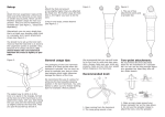
ROSE
MODEL NUMBER
USER INSTRUCTIONS
DYNESCAPE™
MANUALLY CONTROLLED
EMERGENCY DESCENT SYSTEM
! WARNING
National standards and state, provincial and federal laws require the user to
be trained before using this product. Use this manual as part of a user safety
training program that is appropriate for the user's occupation. These
instructions must be provided to users before use of the product and retained
for ready reference by the user. The user must read, and understand (or have
explained), and heed all instructions, labels, markings and warnings supplied with this product and with those products intended for use in association with it. FAILURE TO DO SO MAY RESULT IN SERIOUS INJURY OR DEATH.
1.0
DESCRIPTION OF THE SYSTEM AND COMPONENTS
The Dynescape Descender system is a controlled descent device designed for emergency rescue
of an injured person from aloft, or emergency evacuation (self-rescue) by a person working at
heights. The Dynescape is intended for use in conjunction with Rose anchorage connectors,
connectors, body supports and other components to make up rescue/evacuation systems from
elevations. When combined with other approved Rose components, the Dynescape may be used
for vertical descent from virtually any structure, where suitable anchorage and no obstructions are
present.
THREE MODES OF VERTICAL EMERGENCY DESCENT ARE POSSIBLE:
Mode 1:
Self-rescue by a worker who lowers himself;
Mode 2:
Rescuer climbs down while lowering an injured person and guiding his descent;
Mode 3:
Rescuer remains aloft and lowers an injured person.
All configurations of the system permit trained personnel to effect rescue or evacuation of up to
a 310 lbs. (141 kg) working load with a 10:1 factor of safety, at an average controlled descent speed
of 6.5’ (2 m) per second, over a maximum distance of 1501 (46 m).
Copyright © 2000, Rose Manufacturing Company
P/N 621883 Rev.E
Page 2
USER INSTRUCTIONS ! DYNESCAPE MANUALLY CONTROLLED
! CAUTION
Use the Dynescape descender only for emergency descent of one person at a
time as described in this manual. DO NOT USE DESCENDER FOR FALL
ARREST, WORK POSITIONING OR IN WAYS OTHER THAN SPECIFICALLY DESCRIBED IN THIS MANUAL.
The basic Dynescape descender system consists of the Dynescape descent device, a length of
1/2 inch (13mm) polyester rope terminating in one thimble end and one spliced end (See Figure
1), two carabiner connectors (See Figure 2), and an anchorage connector strap (See Figure 3). These
items are packed in a water resistant carrying bag (See Figure 4). The versatility of this system is
greatly enhanced through use of a full body harness, such as the Rose Pullover Harness (See Figure
5). Optional equipment includes an Installation Snap Hook (See Figure 6).
The Dynescape descender can be operated in one of the following three modes:
MODE 1, SELF-RESCUE:
The worker connects the thimble end of the rope to a suitable overhead anchorage using a
carabiner (or other approved connector). The worker then connects the cam on the descent device
with a carabiner to their approved body support. The free end of the rope is then dropped to the
ground. The worker then takes up slack in the rope to suspend himself from the descender, and
rotates the handle of the descender up to lower himself, controlling his rate of descent. See Figure
7.
MODE 2, RESCUER DESCENDS:
The rescuer connects the thimble end of the rope to a suitable overhead anchorage using a
carabiner (or other approved connector). The rescuer then connects the cam on the descent
device with a carabiner to the injured person’s approved body support. The free end of the rope
is then dropped to the ground. The rescuer takes up slack in the rope to suspend the injured
person from the descender, removes any equipment which might interfere with the rescue, and
then alternately rotates the handle of the descender up to lower the injured person, and climbs
down the structure, guiding the descent of the injured person. The rescuer must have an
independent continuous fall protection system. See Figure 8.
MODE 3, RESCUER REMAINS ALOFT:
The rescuer connects the cam on the descent device with a carabiner to a suitable overhead
anchorage. The rescuer then connects the thimble end of the rope to the injured person using a
carabiner (or other approved connector). The free end of the rope is then dropped to the ground.
The rescuer then takes up the slack to suspend the injured person from the descender device,
disconnects any equipment which might impede descent of the injured person, and rotates the
handle of the descender down to begin lowering and control the rate of descent. The rescuer
must have an independent continuous fall protection system. See Figure 9.
! CAUTION:
Use this system only for the types of rescue specifiaclly detailed in this manual.
Do not attempt to use the system for any other application without first
consulting the manufacturer. Failure to do so may result in serious personal
injury or death.
Other types of emergency descent using the Dynescape desender, such as angular descent of
injured persons, and angular self-rescue from aloft, are possible with different combinations of
components than those described in this manual. These applications require factory engineering
P/N 621883 Rev.E
Copyright © 2000, Rose Manufacturing Company
USER INSTRUCTIONS ! DYNESCAPE MANUALLY CONTROLLED
Page 3
assistance. Contact the Rose Sales Department for information on engineered descent systems.
! CAUTION
Use of the Dynescape requires an anchorage connector connected to an
overhead anchorage with a static tensile strength of at least 5,400 lbs., and
suitable body support for the person being lowered., The anchorage connector and body support will vary depending on the intended application for the
descender. Suitable anchorage connectors should be installed prior to beginning work at any location where the Dynescape might be required. Wherever possible, body supports such as full body harnesses should be worn
during the normal course of work. These measures will save valuable time
during a rescue, This al contains several suggested anchorage connectors.
Consult the manufacturer for additional anchorage connection means for
specific applications.
1.1 DYNESCAPE DESCENDER
The Dynescape descender assembly consists of a central sheave protected by an aluminum
housing; two internal spring-loaded pawls; two rope roller guides; a moving cam; a handle; an
external rope guide; and a length of 1/2 inch (13 mm) three strand twisted polyester rope with one
free end (spliced so the rope may not be removed from the descender) and one metal teardrop
thimble end. See Figure 1.
The rope is reeved between one roller guide and the cam, around the central sheave, and between
the other roller guide and the cam. The thimble end of the rope is used for attachment to an
approved anchorage connector (Modes 1 and 2) or body support (Mode 3). When the descender
is connected to an anchorage connector or body support and the rope is then loaded, the cam
pinches against the rope on the side leading to the free end of the rope and prevents it from sliding
through the descender. Therefore, the descender handle is always rotated towards the rope
thimble to disengage the cam from the rope and begin descent.
The descender permits the rescuer to control the rate of descent by varying the rotation of the
descender handle. Greater rotation of the handle toward the rope thimble decreases the friction
between the cam and the rope and increases the rate of descent; lesser rotation increases the
friction and thus decreases the rate of descent.
The descender incorporates a “dead man’s” feature, and will automatically stop on the line when
the handle is released*
The spring-loaded pawls interact with the housing to prevent the pulley from rotating in the
direction of the thimble end of the rope. The pulley will only rotate in the direction of the free
end of the rope, permitting a user to pull on this end to take up slack between the descender and
the thimble end of the rope.
! CAUTION
The rope is specifically sized for the sheave and selected for compatibility
with the system. Do not attempt to remove or replace the rope.
The external rope guide is permanently attached to the housing. It ensures that the rope enters the
descender at the correct angle, and also helps control the speed of descent.
Copyright ©2000, Rose Manufacturing Company
P/N 621883 Rev.E
Page 4
USER INSTRUCTIONS ! DYNESCAPE MANUALLY CONTROLLED
FIGURE 1:
Dynescape Descender
P/N 506416
! CAUTION
The position of the rope guide is factory set. Do not alter the position of the
rope guide.
Multiple rescues are possible in all modes of use by pulling the rope back through the device from
the free end.
1.2 CARABINER
Two lightweight aluminum carabiners are provided with the system. The carabiners interfacebetween
the anchorage connector and descender, and between the descender and body support. The
connection point varies depending on which mode of rescue is to be used. The carabiner will
normally be compatible with all descender-body support connections. . Depending on the anchorage connector being used, the carabiner may not be a compatible connector between anchorage
connector and descender.
! CAUTION
If any question as to the suitability of the carabiner as a compatible
connector exists, consult the manufacturer for assistance in selecting a
compatible connection means.
P/N 621883 Rev.E
Copyright © 2000, Rose Manufacturing Company
USER INSTRUCTIONS ! DYNESCAPE MANUALLY CONTROLLED
Page 5
The carabiner incorporates a positive locking- mechanism, which requirestwo separate and distinct
manipulations by the user to open and unlock the snaphook gate. When the carabiner gate is
released it will close and lock automatically. See Figure 2.
FIGURE 2
Carabiner
P/N 506259
! CAUTION
Always check
to be sure gate
is closed and
locked.
TO OPEN:
TO CLOSE:
1. Rotate outer gate (A) 90o
1. Release gate and it will
close (C) and lock (D)
2. Depress gate to open (B)
1.3
* NOTE:
Lubricate area about hinge
and inner sleeve (on both
sides of snap).
ANCHORAGE CONNECTOR STRAP
The anchorage connector strap is a highly versatile installation linkage. See Figure 3. It consists of
a length of 3”, (76 mm) wide nylon webbing, with a minimum tensile strength of 5,400 lbs (24 kN).
The anchorage connector strap has a sewn loop at one end, and a D-ring at the other end. It may be
looped around structural members such as beams with a minimum edge radius of 1/32”, (0.8 mm).
The D-ring end is then passed through the sewn loop and the strap cinched down. The thimble
end of the rope (Modes 1 and 2) or descender cam (Mode 3) is then connected to the D-ring using
one of the carabiner connectors.
1.4
CARRYING BAG
The carrying bag is a lightweight, vinyl coated nylon bag with draw string and nylon carrying
handles. See Figure 4. The carrying bag is sized to permit packaging of a complete system for
rescue and evacuation, including the components described above and a separately purchased
body support.
Copyright ©2000, Rose Manufacturing Company
P/N 621883 Rev.E
Page 6
USER INSTRUCTIONS ! DYNESCAPE MANUALLY CONTROLLED
FIGURE 3:
Anchorage Connector Strap
P/N 505282
FIGURE 4:
Carrying Bag
P/N 622080
P/N 621883 Rev.E
Copyright © 2000, Rose Manufacturing Company
USER INSTRUCTIONS ! DYNESCAPE MANUALLY CONTROLLED
Page 7
1.5 OPTIONAL COMPONENTS
! CAUTION
Under no circumstances should products of other manufacturers be used in
conjunction with Rose products or systems without the prior written consent
of Rose Manufacturing Company. Use of incompatible products of other
manufacturers may result in serious personal injury or death and damage to
equipment.
1.5.1 BODY SUPPORTS
The versatility of the Dynescape descender system is greatly enhanced through use of a full body
harness such as the Rose Pullover Harness. Pullover Harnesses are available in various models, with
different combinations of D-rings. The models recommended by the manufacturer for
controlled descent applications incorporate a sternal (chest) D-ring. See Figure 5. If a Pullover
harness with sternal D-ring is the body support, the rescuer may attach the cam (Modes 1 & 2) or
descender rope (Mode 3) directly to the sternal D-ring, take up slack, and commence lowering.
All Pullover harnesses permit adjustment of the harness for different sizes by means of one overall
torso adjustment buckle. A sub-pelvic strap permits the user to attain a seated position during
lowering. The harness straps are color coded to aid in donning.
Depending on model selected, the harnesses incorporate D-rings in various locations. The dorsal
(back) D-ring is provided for attachment of fall arrest lifelines. The sternal (chest) D-ring is used
during lifting/lowering and rescue/evacuation. Shoulder D-rings may be provided for attachment
of a “V” or “Y” retrieval lanyard (with or without spreader bar) for lifting, lowering and
positioning. Hip D-rings may be provided to obtain additional versatility. They permit tie-off
with a suitable lanyard for work positioning only.
Pullover harnesses are made with 1-3/4 inch nylon or polyester webbing, with a minimum tensile
strength of 6,800 lbs. (30 kN). Nylon is recommended for neutral or alkaline environments;
polyester is recommended for acidic environments. The harnesses come with either single pass
friction buckle or tongue buckle thigh straps. Literature describing the range of Rose harnesses is
available from the manufacturer.
1.5.2 INSTALLATION SNAPHOOK
The installation snaphook is a versatile piece of installation hardware as it can often be used without
any special adaptation of the anchorage. See Figure 6. The snaphook is a self-closing, self-locking
connector which requires two separate and distinct manipulations to unlock and open the gate, yet
may be manipulated using only one hand. To open, the spring-loaded gate is rotated 90 degrees
around its axis and then depressed along its hinge axis. To close and lock, the gate is released.
The installation snaphook has a minimum tensile strength of 5,400 pounds (24 kN) and a throat
opening of 2" (51 mm). It is constructed from formed steel, zinc chromate plated ‘to resist
corrosion.
!
CAUTION
Install the installation snaphook so that unwanted movement of the snap
during lowering is prevented. Otherwise, movement of the load may cause
sudden movement of the snaphook and result in loss of balance by the
operator.
The installation snaphook may not be used in Mode 3 rescue to attach the
cam directly to the anchorage.
Copyright ©2000, Rose Manufacturing Company
P/N 621883 Rev.E
Page 8
USER INSTRUCTIONS ! DYNESCAPE MANUALLY CONTROLLED
FIGURE 6:
Installation Snaphook
P/N 506308
! CAUTION
Always check
to be sure gate
is closed and
locked.
TO OPEN:
1. Rotate outer gate (A) 90o
2. Depress gate to open (B)
TO CLOSE:
1. Release gate and it will
close (C) and lock (D)
FIGURE 5:
Pullover Harness
P/N 502733
P/N 621883 Rev.E
Copyright © 2000, Rose Manufacturing Company
USER INSTRUCTIONS ! DYNESCAPE MANUALLY CONTROLLED
Page 9
Contact Rose Manufacturing Company for information on other optional accessories, such as
harness comfort pads, back supports, and spreader bar assemblies.
2.0 USER TRAINING
All users of the emergency descent system must be thoroughly trained in all aspects of installation,
inspection, use and maintenance as described in this manual. However, the instructions contained
in this manual cannot and must not take the place of hands-on training under the supervision of a
competent person.
!
WARNING
THE MANUFACTURER REQUIRES THAT ALL USERS OFTHE SYSTEM RECEIVE
HANDS-ON TRAINING IN ALL ASPECTS OF INSTALLATION, INSPECTION, USE
AND MAINTENANCE UNDER THE SUPERVISION OF A QUALIFIED PERSON.
TRAINING SHOULD BE PERFORNED UNDER CONTROLLED CONDITIONS
WHICH APPROXIM M LIKELY WORK CONDITIONS AND WHICH PROVIDE
BACKUP SAFETY FOR TRAINERS AND TRAINERS. REQUEST SEPARATE
INSTRUCTIONS FROM ROSE MANUFACTURING FOR SUCH A TRAINING
PROGRAM.
If the system is to be used under adverse weather conditions, particular attention should be
focused on:
1.
The restricted mobility due to bulky clothing;
2.
The decrease in endurance due to cold weather conditions;
3.
Environmental hazards that. may affect rescue/evacuation procedures.
A RESCUE PLAN MUST BE ESTABLISHED PRIOR TO BEGINNING WORK AT A
SITE WHERE USE OF THE SYSTEM MAY BE REQUIRED. The rescue plan must take
into account environmental and site specific factors which may affect the ability of rescuers to
perform their roles effectively.
Standby rescue personnel should be available and emergency preparedness training should cover
the steps to be taken to summon trained rescue personnel and the actions to be performed while
awaiting their arrival.
Each member of the work crew should be prepared to assume the duties of any other member
should an emergency situation arise. Training should include the procedures to be followed by all
crew members in case of an emergency and the appropriate first aid procedures to assist an injured
person.
Each member of the work crew should wear the necessary protective equipment at all times during
use of the system. Such protective equipment should include appropriate clothing, protective
headgear and personal fall protection equipment.
Provision should be made for transportation of an injured person to a site which can provide
appropriate medical attention.
Copyright ©2000, Rose Manufacturing Company
P/N 621883 Rev.E
Page 10
USER INSTRUCTIONS ! DYNESCAPE MANUALLY CONTROLLED
!
CAUTION
Node 2 descent (rescuer descending with injured person) affords greater
control of the injured person during descent but will substantially lengthen
the time required to effect a rescue. Rescuers must be trained to evaluate the
condition of an injured person and decide instantly which method of rescue
is indicated.
3.0 INSPECTION AND MAINTENANCE
Before beginning work at any site, first inspect the descender system in accordance with the
instructions in this section. Look for excessive wear, damage, alteration, missing parts, corrosion
and foreign matter that may impair proper function. Make sure that all components are packed in
the order in which they will be needed.
NOTE: The descender system must be formally inspected by a competent person
semi-annually. Inspections should be logged, records preserved and made
available for examination upon request. An inspection log is provided in Appendix
B, and an inspection grid is located on the label near the rope thimble end, for
this purpose.
3.1 INSPECTION OF DESCENDER
Perform the following inspections and refer to Figure 1 for identification of parts.
Check the descender for loose or missing bolts and nuts. Check for presence of the rope guide.
Remove from use and return to the manufacturer if any of these parts are missing.
Check that the cam moves freely between the rope on either side. Check that the roller guides
rotate freely and are not excessively worn. Check that the rope will slide through the descender at
a controlled rate when the cam is disengaged from the rope.
Check that the central sheave moves easily in the direction of the free rope end. A clicking sound
indicates that the internal pawls are operating correctly. Check that the sheave does not rotate in the
opposite direction (toward the rope thimble end).
Remove from use and return to Rose manufacturing Company if the clicking sound is not heard,
or if the sheave rotates in both directions.
Check for excessive corrosion and remove from use if evident.
Check the entire length of the rope for burns, cuts, abrasion or fraying which could impair its
strength. Check for hockling (unlaying) of the twisted rope. If any of these conditions are found,
remove the descender from use and return it to the manufacturer.
!
CAUTION
The rope used with the descender is specifically selected for compatibility
with the descender. No substitution or repair of this rope is possible and must
not be attempted. The free rope end is terminated so that it may not be
removed from the descender. Remove the system from use if any evidence
exists that the rope has been altered or replaced and immediately return it to
the manufacturer.
P/N 621883 Rev.E
Copyright © 2000, Rose Manufacturing Company
USER INSTRUCTIONS ! DYNESCAPE MANUALLY CONTROLLED
Page 11
Check that the rope thimble is secure. Check for the presence of the hog ring that retains the
spliced ends. Check that the labels attached to the thimble end and free end are present and legible.
If any of these items are missing or illegible, remove the descender from use and return to the
manufacturer.
The descender requires no lubrication.
Store the descender in the carrying bag in a clean, dry place out of sunlight and where it cannot
come into contact with corrosives.
3.2 INSPECTION OF THE CARABINERS
Check the operation of each carabiner. It should close and lock automatically when released.
Check to make sure that the spring fully closes the rotating lock. If any defect is found, remove the
carabiner from use and replace it with one which passes inspection.
Check that the carabiner label is present and legible. If not, remove from use until a new label is
obtained and in place.
Check that one carabiner is attached to the rope thimble and the other attached to the descender
cam.
NOTE: If necessary, lubricate the area about the hinge and inner sleeve (on
both sides of the snap) using a silicone based lubricant such as WD-40.
! CAUTION
Gate should not open under pressure from any direction unless intentionally
unlocked. If this condition is not met or if any steps A, B, C, or D described in
Section 4.0 cannot be performed properly, remove carabiner from use.
3.3 INSPECTION OF ANCHORAGE CONNECTOR STRAP
Check the anchorage connector strap for damaged stitching, worn threads, burns, cuts, abrasions or
fraying of web which could impair strength. Check the D-ring for cracks,, bends, nicks,
deformation and corrosion. If any of these conditions is found, immediately remove the anchorage connector strap from use, and replace it with another anchorage connector strap which passes
inspection.
Store the anchorage connector strap in a cool, dry place. Do not store the anchorage connector
strap in direct sunlight for prolonged Periods . The ultraviolet rays of the sun can cause degradation of the webbing.
Clean the anchorage connector strap using warm water and a mild detergent suitable for washing
clothing. Do not use harsh detergents, Harsh detergents will damage the webbing and impair the
strength of the anchorage connector strap. Hang the anchorage connector strap to dry in a dry
place indoors.
3.4 INSPECTION OF CARRYING BAG
Store the carrying bag in a cool, dry place. Do not store the carrying bag in direct sunlight for
prolonged periods. The ultraviolet rays of the sun can cause degradation of the bag material.
The interior of the carrying bag should be kept clean and dry.
Clean the carrying bag using warm water and a mild detergent suitable for washing clothing. Do not
use harsh detergents. Harsh detergents will damage the material. Hang the carrying bag to dry in a
dry place indoors.
Copyright ©2000, Rose Manufacturing Company
P/N 621883 Rev.E
Page 12
USER INSTRUCTIONS ! DYNESCAPE MANUALLY CONTROLLED
Re-package descender system in carrying bag after inspection as follows;
Step l:
Rope coiled into bottom of bag;
Step 2:
Descender laid on top of coiled rope;
Step 3:
Anchorage strap folded, and laid on top of descender.
3.5 INSPECTION OF OPTIONAL COMPONENTS
3.5.1 INSPECTION OF PULLOVER HARNESS
Check the harness for altered, missing or damaged parts. If any of these conditions is found,
immediately remove the harness from use, and replace it with another harness, which passes
inspection.
Store the harness in a cool, dry place. Do not store the harness in direct sunlight for prolonged
periods. The ultraviolet rays of the sun can cause degradation of the harness webbing.
Clean the harness using warm water and a mild detergent suitable for washing clothing. Do not use
harsh detergents. Harsh detergents will damage the webbing and impair the strength of the harness.
Hang the harness to dry in a dry place indoors.
If other components, such as the installation snaphook are part of the descent system, inspect each
of these components according to the instructions which accompanied that product.
4.0 USE OF THE DYNESCAPE DESCENDER SYSTEM
4.1 WORKPLACE ANALYSIS
Before beginning normal work operations at a site where the Dynescape is to be used, it is
extremely important to carefully analyze factors in the work place, which may affect the use of the
descender and related equipment. These factors include work place geometry environmental
factors; the location and nature of work hazards; location and strength of the anchorages on which
the Dynescape anchorage connector will be placed; and the work space of the person(s) to be
connected to the system. Other factors may exist which cannot be foreseen by the manufacturer
but will become evident to the competent or qualified person at the work place who makes or
supervises the installation. Take enough time to consider all foreseeable possibilities.
Evaluate the expected vertical travel of a load during rescue to identify areas of danger. THE
DESCENDER LINE MUST BE ABLE TO EASILY EXTEND DOWNWARD TO THE
LOWEST EXPECTED WORK ELEVATIONE THE LINE SHOULD NOT CONTACT
SHARP EDGES OR PASS TOO CLOSE TO OBJECTS WHERE IT CAN BECOME
LODGED, BURNED OR CUT. Never plan a rescue path close to an electrical hazard.
Once the descender system has been thoroughly checked in accordance with the instructions in
Section 3.0 it will remain unused during the normal course of work at a site. If emergency rescue
of one or more persons is required, first summon additional rescue personnel to stand by at
ground level. FOLLOW THE EMPLOYER’S RESCUE PLAN. THE EMERGENCY
PLAN MUST IDENTIFY SUITABLE ANCHORAGES TO BE USED DURING THE
RESCUE AND APPROVED ANCHORAGE CONNECTORS.
NOTE: Rose Manufacturing Company is able to provide assistance with hazard
analysis, rescue procedure design and training, and design, manufacture and
installation of anchorage connectors and engineered rescue systems.
P/N 621883 Rev.E
Copyright © 2000, Rose Manufacturing Company
USER INSTRUCTIONS ! DYNESCAPE MANUALLY CONTROLLED
4.2 MODE 1:
Page 13
SELF-RESCUE (EVACUATION)
The equipment required for self rescue or evacuation is:
1. Descender system;
2. Rose Pullover Harness with sternal (chest) D-ring or other body support approved by Rose;
3. Appropriate personal protective equipment (hard hat, gloves, etc.).
Perform the following steps in sequence for self rescue or, evacuation.
4.2.1
Attach the selected anchorage connector to an overhead anchorage.
NOTE: The Dynescape descender is shipped from the factory with approximately
61 (1.8m) of rope terminated with the thimble extending above the descent device
to facilitate connection to the anchorage connector or body support. If more rope
is needed to effect the connections, it must be fed through the device from the free
end. It is not possible to pull on the thimble end to obtain additional rope. See
Figure 10.
4.2.2
Connect the rope thimble to the anchorage connector using the carabiner or other connector
supplied.
To unlock and open the carabiner gate perform the following steps and refer to Figure 20
Step 1:
Step 2:
Rotate gate 90 degrees about its axis (unlock).
Depress gate until it pivots about hinge (open).
To close and lock the gate*
Step 3:
Release gate and it should swing back and contact the nose (close).
Step 4:
The gate should then rotate 90 degrees and engage the nose (lock).
4.2.3
Drop the free end of the rope to the surf ace from which evacuation. MAKE SURE THE
ROPE EXTENDS FREELY DOWN TO THE EVACUATION AREA AND IS NOT KNOTTED OR KINKED.
4.2.4
Use the remaining carabiner to connect the descender cam to the chest D-ring of the Pullover
Harness, or to another designated attachment point, depending on the body support being used.
See Figure 7.
4.2.5
Pull on the free end of the rope to take up slack between the descender and thimble end of the
rope, until suspended from the descender rope.
Copyright ©2000, Rose Manufacturing Company
P/N 621883 Rev.E
Page 14
USER INSTRUCTIONS ! DYNESCAPE MANUALLY CONTROLLED
FIGURE 7:
Mode 1:
Self-Rescue/Evacuation
4.2.6
Rotate the handle of the descender in the direction of the rope thimble end to begin descent . The
direction is up for Mode 1 rescue (self-rescue or evacuation). Move the handle in the opposite
direction to slow and stop the descent. TWO hands are normally required to control the
descender.
!
CAUTION
To eliminate sudden movement of descender, maintain a firm grip on the
descender handle when transferring weight to the descent system, and
transfer weight gradually.
Emergency descent of more than one person is possible using the descender system. The next
P/N 621883 Rev.E
Copyright © 2000, Rose Manufacturing Company
USER INSTRUCTIONS ! DYNESCAPE MANUALLY CONTROLLED
Page 15
person aloft retrieves the descender by pulling the rope up, then pulls the rope back through the
device from the free end, and lowers the free end back down to ground level. The next person is
then connected to the system and lowering effected according to the instructions above.
!
CAUTION
Once the Dynescape descender has been used in a rescue or evacuation,
it must be immediately removed from service and returned to the
manufacturer for inspection and service.
4.3 MODE 2: RESCUE OF AN INJURED PERSON, RESCUER DESCENDS
The equipment required for rescue is:
l.
Descender systems;
2.
Rose Pullover Harness with sternal (chest) D-ring or other body support approved by Rose;
3.
Appropriate personal protective equipment (hard hat, gloves, etc.).
4.
Personal fall arrest equipment to be used by the rescuer.
Perform the following steps in sequence to rescue the person from aloft.
4.3.1
Attach the selected anchorage connector to an overhead anchorage.
NOTE: The Dynescape descender is shipped from the factory with approximately
61 (1.8m) of rope terminated with the thimble extending above the descent device
to facilitate connection to the anchorage connector or body support. If more rope
is needed to effect the connections, it must be fed through the device from the free
end. It is not possible to pull on the thimble end to obtain additional rope. See
Figure 10.
4.3.2
Connect the rope thimble to the anchorage connector using the carabiner or other connector
supplied. See Figure 8.
To unlock and open the carabiner gate, perform the following and refer to Figure 2:
Step 1:
Rotate gate 90 degrees about its axis (unlock).
Step 2:
Depress gate until it pivots about hinge (open).
To close and lock the gate
Step 1:
Release gate and it should swing back and contact the nose (close).
Step 2:
The gate should then rotate 90 degrees and engage the nose (lock).
4.3.3
Drop the free end of the rope to the surface from which evacuation to medical facilities will be
effected.
MAKE SURE THE ROPE EXTENDS FREELY DOWN TO THE
EVACUATION AREA AND IS NOT KNOTTED OR KINKED.
Copyright ©2000, Rose Manufacturing Company
P/N 621883 Rev.E
Page 16
USER INSTRUCTIONS ! DYNESCAPE MANUALLY CONTROLLED
4.3.4
Use the remaining carabiner to connect the descender cam to the chest D-ring of the injured
personts Pullover Harness, or to another designated attachment point, depending on the body
support or rescue support being used. See Figure 8.
!
CAUTION
Take care to move the injured person as little as possible during rescue.
Make sure that no part of the injured Persons body or equipment is dangling
in a way that presents a snag hazard, which might prevent lowering.
4.3.5
Pull on the free end of the rope to take up slack between the descender and thimble end of the
rope, so that the injured person is suspended from the descender rope.
FIGURE 8:
Mode 2:
Emergency Rescue, Rescuer Descends
P/N 621883 Rev.E
Copyright © 2000, Rose Manufacturing Company
USER INSTRUCTIONS ! DYNESCAPE MANUALLY CONTROLLED
Page 17
4.3.6
If the injured person is suspended from equipment used for positioning or fall protection,
disconnect that equipment.
!
CAUTION
Be careful not to drop surplus equipment to the surface below, to avoid
injury to surface level rescuers. If it is necessary to cut any equipment off the
injured person, be careful not to cut the descender rope.
4.3.7
Rotate the handle of the descender in the direction of the rope thimble end to begin descent of
the injured person. This direction is up for Mode 2 rescue (rescuer descending with injured
person).
Move the handle in the opposite direction to slow and stop the descent.
!
CAUTION
To eliminate sudden movement of the descender, maintain a firm grip on the
descender handle when transferring weight to the descent system, and
transfer weight gradually.
4.3.8
The rescuer must alternately climb down and then lower the injured person to guide their descent.
This requires that the rescuer climb down so the descender is within reach above his head, and
then operate the descender so it slides down the rope to approximately waist level. The rescuer
then climbs down so the descender is again above head height, and repeats the sequence. The
rescuer must have separate continuous fall protection.
!
CAUTION
Mode 2 descent affords greater control of the injured person during descent
than Mode 3, but will substantially lengthen the time required to effect a
rescue. Rescuers must be trained to evaluate the extent of injury to an
injured person and decide instantly while aloft which method of rescue is
indicated.
Emergency descent of more than one person is possible using the descender system. To effect
multiple descents for Mode 2, the rescuer pulls the descender up while climbing aloft. The
rescuer then pulls the rope back through the device from the free end and lowers the free end back
down to ground level. The next injured person is then connected to the system and lowering
effected according to the instructions above.
!
CAUTION
The rescuer in no case is to attempt descent using the descender while the
injured person is connected to the descender. Attempting to do so may result
in serious injury or death.
Once all rescues have been accomplished, the rescuer may attach himself to the descender and
descend to ground level, by following instructions for Mode 1, self-rescue/evacuation.
Copyright ©2000, Rose Manufacturing Company
P/N 621883 Rev.E
Page 18
USER INSTRUCTIONS ! DYNESCAPE MANUALLY CONTROLLED
!
CAUTION
Once the Dynescape descender has been used in a rescue or evacuation, it
must be immediately removed from service and returned to the
manufacturer for inspection and service.
4.4 MODE 3: RESCUE OF AN INJURED PERSON, RESCUER REMAINS
ALOFT
The equipment required for rescue is:
l.
Descender system;
2.
Rose Pullover Harness with sternal (chest) D-ring or other body support approved by Rose;
3.
Appropriate personal protective equipment (hard hat, gloves, etc.);
4.
Personal fall arrest equipment to be used by the rescuer.
Perform the following steps in sequence to rescue the person from aloft.
4.4.1
Attach the selected anchorage connector to an overhead anchorage.
NOTE: The Dynescape descender is shipped from the factory with approximately
61 (1.8m) of rope terminated with the thimble extending above the descent device
to facilitate connection to the anchorage connector or body support. If more rope
is needed to effect the connections, it must be fed through the device from the free
end. It is not possible to pull on the thimble end to obtain additional rope. See
Figure 10.
4.4.2
Connect the descender cam to the anchorage connector using the carabiner attached to the cam.
To unlock and open the carabiner gate:
Step 1:
Rotate gate 90 degrees about its axis (unlock).
Step 2:
Depress gate until it pivots about hinge (open).
To close and lock the gate:
Step 1:
Release gate and it should swing back and contact the nose (close).
Step 2:
The gate should then rotate 90 degrees and engage the nose (lock).
4.4.3
Drop the free end of the rope to the surface from which evacuation to medical facilities will be
effected.
MAKE SURE THE ROPE EXTENDS FREELY DOWN TO THE
EVACUATION AREA AND IS NOT KNOTTED OR KINKED.
4.4.4
Use the remaining carabiner to connect the rope thimble to the chest D-ring of the injured
person’s Pullover Harness, or to another designated attachment point, depending on the body
support or rescue support being used. See Figure 9.
P/N 621883 Rev.E
Copyright © 2000, Rose Manufacturing Company
USER INSTRUCTIONS ! DYNESCAPE MANUALLY CONTROLLED
!
Page 19
CAUTION
Take care to move the injured person as little as possible during rescue.
Make sure that no part of the injured person’s body or equipment is dangling
in a way which presents a snag hazard which will prevent lowering.
4.4.5
Pull on the free end of the rope to take up slack between the descender and thimble end of the
rope, so that the injured person is suspended from the descender rope.
FIGURE 9:
Mode 3:
Emergency Rescue, Rescuer Remains Aloft
Copyright ©2000, Rose Manufacturing Company
P/N 621883 Rev.E
Page 20
USER INSTRUCTIONS ! DYNESCAPE MANUALLY CONTROLLED
4.4.6
If the injured person is suspended from equipment used for positioning or fall protection,
disconnect that equipment.
!
CAUTION
Be careful not to drop surplus equipment to the surface below, to avoid
injury to surface level rescuers. If it is necessary to cut any equipment off the
injured person, be careful not to cut the descender rope.
4.4.7
Rotate the handle of the descender in the direction of the rope thimble end to begin descent of
the injured person. The direction is down for Mode 3 rescue (rescuer remains aloft). Move the
handle in the opposite direction to slow and stop the descent. Two hands are normally required
to control the descender.
!
CAUTION
To eliminate sudden movement of descender, maintain a firm grip on the
Descender handle when transferring weight to the descent system, and
transfer weight gradually.
Emergency descent of more than one person is possible using the descender system. To effect
multiple descents for Mode 3 rescue,, the rescuer retrieves the thimble end of the rope by pulling
the rope back through the device from the free end and lowers the free end back down to ground
level. The next injured person is then connected to the system and lowering effected according
to the instructions above.
!
CAUTION
The rescuer in no case is to attempt descent using the descender while the
injured person is connected to the descender. Attempting to do so may result
in serious injury or death.
Once all rescues have been accomplished, the rescuer may attach himself to the descender and
descend to ground level, by following instructions for Mode 1, self rescue/evacuation.
!
CAUTION
Once the Dynescape descender has been used in a rescue or evacuation,
it must be immediately removed from service and returned to the
manufacturer for inspection and service.
P/N 621883 Rev.E
Copyright © 2000, Rose Manufacturing Company
USER INSTRUCTIONS ! DYNESCAPE MANUALLY CONTROLLED
Page 21
FIGURE 10:
Back-Threading
the Dynescape Lifeline
To thread the rope back
through the device, start with
the free end of the rope and
work the rope in the
direction of the arrows, as
shown. Back thread short
sections of rope at a time,
until the thimble end of the
rope is the desired length.
5.0 SERVICE AND SPARE PARTS
Except as described in Section 3. 0, Inspection and Maintenance, the Dynescape descender system
has no user serviceable parts The factory is the only authorized service location.
Replacement components and service may be obtained by contacting.
ROSE MANUFACTURING COMPANY
2250 SOUTH TEJON STREET
ENGLEWOOD, COLORADO 80110-1041
PHONEE. (303) 922-6246
TOLL FREE*. (800) 722-1231
FAX*. (303) 934-9960
Replacement components will only be shipped as complete assemblies.
Copyright ©2000, Rose Manufacturing Company
P/N 621883 Rev.E
Page 22
USER INSTRUCTIONS ! DYNESCAPE MANUALLY CONTROLLED
5.1 ORDERING SERVICE AND REPLACEMENT PARTS
When ordering spares, follow the directions below.
5.1.1
Identify the part number of the component to be replaced.
5.1.2
Contact the manufacturer at the address and phone number listed above to order the replacement
component. The following information is required when ordering:
a)
Part number and description of component to be replaced;
b)
Contact person for the manufacturer in case additional information is required;
c)
Contact person address and telephone number;
d)
Name of person ordering the replacement component;
e)
Shipping address for the replacement component;
f)
Purchase order authorizing the manufacturer to furnish the replacement component.
Please note that all descenders returned to the factory must, at a minimum, be disassembled,
cleaned and inspected before re-assembly. Therefore a service charge will apply for all systems
and/or components returned to the factory.
Upon receipt of an order, the manufacturer will supply a return shipping date.
If inquiring about an order that has already been placed, be prepared to provide the information
listed above, as applicable, and the date on which the order was placed.
The manufacturer will provide estimated packaging and shipping costs to permit calculation of the
total purchase order amount required. Shipments are made FOB Englewood, Colorado, USA.
Freight charges are normally prepaid and added to the invoice unless other arrangements are made
in advance.
6.0
LABELS AND MARKINGS
6.1
The following labels must be present, legible and securely attached to the Dynescape Manually
Controlled Descender. The Formal Inspection Grid must be punched with a date (month/year)
within the last six months. If not, remove the Dynescape Manually Controlled Descender from use
and mark it as “UNUSABLE” until a Formal Inspection is performed.
CARRYING BAG LABEL
P/N 621883 Rev.E
Copyright © 2000, Rose Manufacturing Company
USER INSTRUCTIONS ! DYNESCAPE MANUALLY CONTROLLED
Page 23
MODEL IDENTIFICATION LABEL
ATTACHED TO CARRYING BAG
ROPE FREE END LABEL
IDENTIFICATION LABEL
WARNING LABEL
INSPECTION GRID
LIFELINE IDENTIFICATION LABEL
THIMBLE END LABEL
Copyright ©2000, Rose Manufacturing Company
P/N 621883 Rev.E
Page 24
USER INSTRUCTIONS ! DYNESCAPE MANUALLY CONTROLLED
DYNESCAPE DESCENDER LABELS
P/N 621883 Rev.E
Copyright © 2000, Rose Manufacturing Company
Rose Part No.:
Date of Mfg.:
Date of Inspection
Inspector
Dynescape Descender
Bolts and Nuts
Rope Guide
Cam
Roller Guides
Rope Movement
USER INSTRUCTIONS ! DYNESCAPE MANUALLY CONTROLLED
Serial No.:
7.0 DYNESCAPE SYSTEM INSPECTION
Copyright ©2000, Rose Manufacturing Company
7.1 DYNESCAPE SYSTEM INSPECTION LOG
Sheave Rotation
Internal Pawls
Corrosion
Labels
Page 25
P/N 621883 Rev.E
Continued on Back of Page
Page 26
P/N 621883 Rev.E
Continued from Front of Page
Lifeline
Rope Wear/Damage
Hockling
Rope Thimble
Splices
Labels
Labels
Strap
Webbing Wear/Damage
D-Ring
Copyright © 2000, Rose Manufacturing Company
Bag
Environment
Clean/Dry Interior
Out of Sunlight
Note: For a complete description of inspection criteria, refer to User Manual, Section 3.0.
USER INSTRUCTIONS ! DYNESCAPE MANUALLY CONTROLLED
Carabiners
Operational Check
Attachments
USER INSTRUCTIONS ! DYNESCAPE MANUALLY CONTROLLED
Page 27
DYNESCAPE™ MANUALLY CONTROLLED
EMERGENCY DESCENT SYSTEM
OWNER REGISTRATION
IMPORTANT: Fill out this form at the time of purchase. A duplicate is provided with each new
unit which must be filled out and returned to Rose Manufacturing Company. If ownership
changes, the new owner must contact Rose Manufacturing Company to re-register the unit.
Serial Number:
Model Number:
OWNER:
Name:
Permanent Address:
Telephone:
Dynescape Manually Controlled Emergency Descent System
Custodian and Title:
PURCHASED FROM:
Name:
Address:
DATE OF PURCHASE:
Month
Day
Copyright ©2000, Rose Manufacturing Company
Year
P/N 621883 Rev.E
Page 28
USER INSTRUCTIONS ! DYNESCAPE MANUALLY CONTROLLED
WARRANTY
Express Warranty – Rose/MSA warrants that the product furnished is free from
mechanical defects or faulty workmanship for a period of one (1) year from first use or
eighteen (18) months from date of shipment, whichever occurs first, provided it is
maintained and used in accordance with Rose/MSA’s instructions and/or recommendations. Replacement parts and repairs are warranted for ninety (90) days from the
date of repair of the product or sale of the replacement part, whichever occurs first.
Rose/MSA shall be released from all obligations under this warranty in the event
repairs or modifications are made by persons other than its own authorized service
personnel or if the warranty claim results from misuse of the product. No agent,
employee or representative of Rose/MSA may bind Rose/MSA to any affirmation,
representation or modification of the warranty concerning the goods sold under this
contract. Rose/MSA makes no warranty concerning components or accessories not
manufactured by Rose/MSA, but will pass on to the Purchaser all warranties of manufacturers of such components. THIS WARRANTY IS IN LIEU OF ALL OTHER WARRANTIES, EXPRESS, IMPLIED OR STATUTORY, AND IS STRICTLY LIMITED TO THE TERMS
HEREOF. ROSE/MSA SPECIFICALLY DISCLAIMS ANY WARRANTY OF MERCHANTABILITY OR FITNESS FOR A PARTICULAR PURPOSE. For additional information please
contact the Customer Service Department at 1-800-MSA-2222 (1-800-672-2222).
ROSE MANUFACTURING COMPANY ! 2250 SOUTH TEJON STREET
ENGLEWOOD ! COLORADO ! 80110-1000 ! USA
TEL. (303) 922-6246 ! TOLL FREE (800) 722-1231 ! FAX (303) 934-9960
Dynescape™ Descender and Pullover™ Harness are trademarks, rights to which
are held by Rose Manufacturing Company, U.S.A. Protected by the following U.S.
patents: 4,589,523; 4,434,536; 5,361,867. Foreign patents issued and applied for.
P/N 621883 Rev.E
Copyright © 2000, Rose Manufacturing Company