1
DPO7000C Series Datasheet - DPO7000C Series
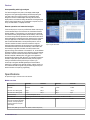
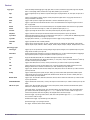
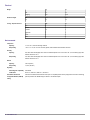
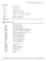
Pinpoint® trigger system
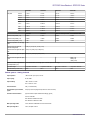
Trigger sensitivity
Internal DC coupled
0.7 div from DC to 50 MHz, increasing to 1.2 div at rated analog bandwidth (typical), up to 2.5 GHz. 2.5 div at 3.5 GHz
Aux input (external trigger)
1 MΩ
250 mV from DC to 50 MHz, increasing to 350 mV at 250 MHz (typical)
Trigger delay by time
3.2 ns to 3,000,000 s
Trigger delay by events
1 to 2,000,000,000 events
Main trigger modes
Auto, Normal, and Single
Enhanced triggering
Enhanced triggering corrects the difference in timing between the trigger path and the acquired data path (supports all Pinpoint
trigger types on both A- and B-Events except pattern trigger); Default On (user-selectable); Not available in FastAcq mode.
Trigger sequences
Main, Delayed by Time, Delayed by Events, Reset by Time, Reset by State, Reset by Transition, B Event Scan. All sequences can
include separate horizontal delay after the trigger event to position the acquisition window in time.
Communications-related triggers
Support for AMI, HDB3, BnZS, CMI, MLT3, and NRZ encoded communications signals. Select among isolated positive or negative
one, zero pulse form, or eye patterns as applicable to the standard. Requires Option MTM .
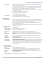
Video trigger formats and field
rates
Triggers from negative sync composite video, field 1 or field 2 for interlaced systems, any field, specific line, or any line for
interlaced or noninterlaced systems. Supported systems include NTSC, PAL, SECAM, and HDTV 1080/24sF, 1080p/25, 1080i/50,
1080i/60, 1080p/24, 720p/60, 480p/60
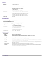
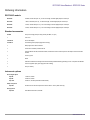
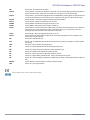
Serial pattern trigger
NRZ-Encoded Data
Clock recovery system
DPO7254C and DPO7354C only, requires Opt. ST1G. Up to 64 bit serial word recognizer, bits specified in binary (high, low, don't
care) or hex format. Trigger on NRZ-encoded data up to 1.25 GBaud.
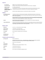
(DPO7254C and DPO7354C only, requires Opt. ST1G or MTM)
Clock recovery phase locked
loop bandwidth
Fixed at FBaud/500
Clock recovery frequency
range
1.5 MBaud to 1.25 GBaud
Clock recovery jitter (RMS)
20 psRMS + 1.25% Unit Interval RMS for PRBS data patterns
20 psRMS + 1.25% Unit Interval RMS for repeating "0011” data pattern
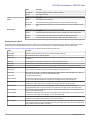
Clock recovery tracking/
acquisition range
±5% of requested baud rate (typical)
Minimum signal amplitude
needed for clock recovery
1 divp-p up to 1.25 Gbaud
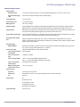
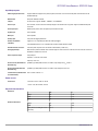
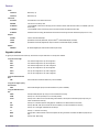
Trigger level range
Any channel
±12 divisions from center of screen
Auxiliary input
TekVPI interface; ±5 V (50 Ω); 150 V, derate at 20 dB/decade to 9 VRMS above 200 kHz (1 MΩ)
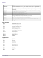
Line
Fixed at 0 V
Trigger coupling
DC
AC (attenuates <60 Hz)
HF Rej (attenuates >30 kHz)
LF Rej (attenuates <80 kHz)
Noise Reject (reduces sensitivity)
Trigger holdoff range
250 ns min to 100 s
www.tektronix.com 13