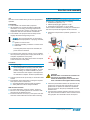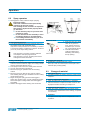
1
Operation manual Type: ❍ 24026 ❍ 24053 ❍ 24071 ❍ 28023 ❍ 28048 ❍ 28064 ❍ 38032 ❍ 38042 ❍ 44024 ❍ 44032 WIWA Professional Serial-No. …………………… Translation of original operation manual WIWA Professional Professional · DBK · en · 02.12 · jw EC-Declaration of conformity according to Appendix ll, No. 1 A of the Machinery Directive 2006 / 42 / EC, modified by 2009 / 127 / EC The company WIWA Wilhelm Wagner GmbH & Co. KG Gewerbestr. 1-3 35633 Lahnau Germany herewith declares that the equipment types Professional 24026; 24053; 24071; 28023; 28048; 28064; Professional 38032; 38042; Professional 44024; 44032 with Serial-No. ____________________ are in conformance with the provisions of the above-mentioned directive. Documentary authority: WIWA GmbH, Tel. +49 6441 609 0 Lahnau, 11.01.2012 Place, Date Heidrun Wagner-Turczak Managing Director Declaration of Conformity according to ATEX-Directive 94 / 9 / EC The company WIWA Wilhelm Wagner GmbH & Co. KG Gewerbestr. 1-3 35633 Lahnau Germany herewith declares that the equipment types Professional 24026; 24053; 24071; 28023; 28048; 28064; Professional 38032; 38042; Professional 44024; 44032 with Serial-No. ____________________ are in conformance with the provisions of the above-mentioned directive. The listed equipment is assigned to Group II, Category 2 G. Marking: II 2G cT4 Lahnau, 11.01.2012 Place, Date 2 Heidrun Wagner-Turczak Managing Director Translation of the original declaration of confomity Professional · DBK · en · 01.12 · ju Contents1 1.1 Table of contents 1Contents 1.1 Table of contents 1.2 Preface 1.3 First read, then start 3 3 4 4 2Safety 5 2.1 Description of symbols 5 2.2 Warning instructions located on the machine 5 2.3 Dangers arising from the equipment 5 2.4 Application of the machine 6 2.5 Machine surroundings 7 2.6 Sources of danger 7 2.7 Operating staff 8 2.8 Installation site 8 2.9 Behavior in case of emergency 9 2.10 Safety features 9 2.11 Pump handling and auxiliary materials 10 2.12 Transporting 10 3 Component description 11 4 Erection and assembly 12 5Start-up14 5.1 First cleaning 14 5.2 Checking pressure 15 6Operation16 6.1 Equipment preparation 16 6.2 Spray operaton 17 6.3 Change of material 17 7 Shutting down18 8 8.1 8.2 8.3 8.4 Maintenance19 Regular inspections 19 Maintenance plan 19 High pressure filter 19 Maintenance unit 19 9 Malfunctions and troubleshooting22 10 10.1 10.2 10.3 10.4 Appendix23 Technical specifications 23 Auxiliary materials 23 Machine card 24 Certificate of training and operation 24 Translation of the original operation manual Airless3 •Professional_BAoDB_en_1011•ski 1Contents 1.2Preface 1.3 This User’s Handbook must always be available to operating staff The operating authority of the equipment must ensure, that a user`s handbook is available to the operator, in a language which he understands. Dear customer! Thank you for your decision to purchase ment. equip- In the user’s handbook, you can find all information required for the proper handling of your Airless Paint Spraying Machine. However, for safe operation, there are further essential details which you should adhere to: Please read and observe the guidlines valid for your country. In Germany, the "Richtlinien für Flüssigkeitsstrahler" (Guidelines for fluid sprayers) published by: Hauptverband der Gewerblichen Berufsgenossenschaften (Industrial Employer's Liability Insurance Association), are valid. Manufacturer’s notes and operating guidelines for coating and pumping materials should be observed at all times. No method of operation should be exercised which impairs the safety of products and the operating personnel. We wish you much success and excellent working results when appliying your Airless Paint Spraying Machine. WIWA Wilhelm Wagner GmbH & Co. KG. Copyright © 2009 WIWA Copyright ownership for this user manual remains with WIWA WILHELM WAGNER GmbH & Co. KG Gewerbestr. 1-3 • 35633 Lahnau Phone: +49 (0)6441 609-0 • Fax: +49 (0)6441 609-50 E-mail: [email protected] • Internet: www.wiwa.de This operating manual is solely intended for personnel involved in preparation, operation and servicing. It is prohibited to pass on this operating manual for reproduction, utilisation or communication of its contents, unless this has been explicitly permitted. Infringements incur an obligation to pay damage compensation. All rights reserved in the event of registration of the patented design, industrial design or registered design. This operating manual only applies in conjunction with the machine card that was given to you with the user manual for your equipment. Please check that the type plate data is identical with the information on the machine card. Please notify us immediately if there are discrepancies, if the user manual has been incorrectly compiled or if the type plate is missing. 4 First read, then start Remember that Airless Paint Spraying Equipment works under extreme pressure and that high levels of spraying pressure are created! ➤➤ Never hold your finger or hand in front of the gun and never reach into the spray. ➤➤ Never point the spray gun towards yourself, other people or other living creatures. ➤➤ Always pay close attention to the references and specifications found in the user's handbook! Before each usage, be especially certain to: ➤➤ Check the grounding conditions (for the unit and the object to be sprayed). ➤➤ Check the seal of all connecting and mounted parts. ➤➤ Observe the maximal allowed pressure of the unit and accessory parts. Beforebeginning any work on the equipment and at any pause during operation, be absolutely required to: ➤➤ Turn off the spraying equipment at the air pressure stop valve. ➤➤ Release the pressure found in the spraying gun and hose. ➤➤ Secure the spraying gun. Pay attention to safety! The accident prevention regulation "Handling of Coating Materials" (BGV B3) and the guidelines covering fluid sprayers ZH1/406 from the German Employer's Liability Insurance Association are to be observed without fail. To ensure a safe operating environment, the condition of fluid sprayers must be inspected by an expert every 12 months or sooner, if deemed necessary. A written record of the inspection results is to be kept. Remaining paint and solvent are to be disposed of according to legal regulations. This also applies for environmently friendly water lacquer or enamel systems. In case of injuries, consult a physician or go to the next hospital without delay. If paint/material or solvent has gone into the skin, the physician has to be informed about the type of paint/material or the solvent applied.Therefore, always ensure that the product specification sheet, with address and telephone number of the manufacturer, is at your disposal! Translation of the original operation manual Airless •Professional_BAoDB_en_1011•ski Safety2 2.1 Description of symbols Warning signs and symbols may not be removed from the machine. Damaged and illegible warning signs and symbols are to be replaced immediately. NOTE This marks a section of text which is especially relevant to safety. Special attention should be paid to this section and the contents strictly observed. The following signs are located on the machine: ➤➤ On the high pressure filter: Warning sign covering the grounding of the machine (picture 2.2.1) The signs and symbols used in this User's Handbook have the following meaning: SMOKING PROHIBITED This marks a situation in which a fire hazard arises through the use of flammable or explodable solid, fluid or gaseous materials. WARNING This marks a situation which could be dangerous. If not observed,death or very serious injuries could result. Picture 2.2.1 DANGER OF EXPLOSION This marks a situation, where there is danger of explosion. Observation of this information is absolutely essential. ELECTRICAL VOLTAGE This marks a situation, where there is a danger of explosion through an electostatic charge. Observation of this information is absolutely essential. USE EAR PLUGS For health reasons, it is very important to pay attention to this warning. Picture 2.2.2 USE BREATHING PROTECTION For health reasons, it is very important to pay attention to this warning. HEALTH DANGER This marks materials which are hazardous to your health. Observation of this information is absolutely essential. FIRST AID In case of injuries or accidents, these instructions should be absolutely adhered to. 2.2 Warning instructions located on the machine Warning signs and symbols which have been placed on the machine are there to inform of possible dangers and must be observed. Translation of the original operation manual Airless •Professional_BAoDB_en_1011•ski Picture 2.2.3 2.3 The propietor is required according to the German Accident Prevention Regulation (Unfallverhütungsvorschrift), BGR 500, Kap. 2.29, to ensure that the machine is properly grounded. Please, observe our instruction manual. ➤➤ On the material pump cylinder: Nameplate (picture 2.2.2) Please observe that the information located on the nameplate corresponds to data found on the machine card. We request immediate notification should there be any discrepancies or if the nameplate is missing. ➤➤ Picture 2.2.2 Safety information This sign lists the most important safety guidlines for operating this piece of equipment. Please read this information carefully as well as adhering to all instructions located in this User's Handbook! Dangers arising from the equipment This machine was designed and built in accordance with all safety aspects. It corresponds with the present standards of technical regulations and current rules for accident prevention. 5 2Safety It left the factory in perfect condition and warrants a high level of safety. However, the following dangers exist if operated incorrectly or used inappropriately: ➤➤ to life and limb of operator or third personsor ➤➤ for the machine and other property belonging to owner of machine ➤➤ for the efficient working of the machine All personnel involved in the starting, operation and maintenance of the machine must read the following notes carefully and observe them. It is a matter of their safety! We recommend that the machine operation management have this confirmed in writing. 2.4 Application of the machine The Airless Paint Spraying Machines were especially designed for strong corrosion protection. Modell: 24053, 24071, 28048, 28064 These airless paint spraying units are suitable for working with both low and high viscosity, high-built materials, regardless whether they are water or solvent based. Low solvent and solvent-free materials can be processed as well. These machines are optimal for spraying applications using longer fluid hoses and larger tip-bores, as well as for spraying under high pressure conditions. Model: 38032, 38042, 44024, 44032 These airless paint spraying machines were especially developed for the use of coarse-pigmented or abrasive materials having a low to middle level of viscosity, such as zinc primer, ferric oxide, zinc silicate on a solvent basis, glass flake, printing ink, flame protection and other heavily pigmented or fibrous materials. These machines are known for their ability to handle a large volume of material flow, even when using large tip openings and low piston speeds and to keep unit wear at a minimum. They are especially well suited when using automatic paint spraying systems either with or without circulation. Using this equipment in areas requiring protection from explosions Marking: II 2G cT4 This equipment fulfills the explosion-proof requirements found in the guideline 94/9/EC for the type of explosion, equipment catagory and temperature class found on the nameplate). This equipment is able to be installed in areas requiring Zone I explosion protection. Due to the possibility that explosive gases and overspray may be created, this unit is to 6 be considered as Group II, Equipment Catagory 2G. The flash point for the materials being sprayed, as well as the solvent being used, must be above 200°C. When operating this equipment, the User‘s Handbook must be followed closely. The required inspection and maintenance intervals must be adhered to strictly. All information found on the unit‘s signs or plates must be adhered to and not exceeded. Do not allow this unit to be overloaded. It is the responsibility of the operator of this equipment to determine the explosion risk (zone determination according to EC regulation 94/9/EC, Appendix II, Nr. 2.1-2.3) in the area of usage, in accordance with local regulatory authority guidelines. Furthermore, it is the responsibility of the operator on-sight to check and ensure that the technical specifications and markings according to ATEX are compliant with local requirements. Please observe that some components have their own nameplate with separate markings according to ATEX. The marking with the lowest rating for explosion protection becomes valid for the entire system. If the intended application could lead to injury of personnel if this equipment malfunctions, on-sight precautions and preventive measures must be implemented If this equipment appears to be malfunctioning or behaving strangely during operation, the unit must be shut down immediately and Customer Service contacted as soon as possible. It must be ensured that the unit is grounded either separately or together with the equipment it is mounted to (maximum resistance 106 Ω, picture 2.4.1 ground / potential equalization). Picture 2.4.1 Spaying machines which are not protected against explosions may not be used in workplaces which fall under the regulation covering explosion protection. Pneumatically driven airless spraying machines are not affected by this. Should, however, additional electrically driven accessories be mounted to these machines, such as agitators or heaters, the regulation covering explosion prevention must be checked for compliance. Plugs for heaters, agitators, etc. which are not protected against explosions may only be plugged into sockets located outside of areas that fall under the regulation covering explosion prevention, even if the accessory being used is explosion protected. Translation of the original operation manual Airless •Professional_BAoDB_en_1011•ski Safety2 Other usage is not in line with regulations. Before equipment is used for other purposes or with other materials, and, therefore, not according to the regulations, permission should be obtained from the manufacturer, as the guarantee is otherwise invalid. The observation of technical documentation and the compliance with specified operational, maintenance and starting guidelines are manditory in accordance with the valid regulations. 2.5 Machine surroundings Rebuilds and changes For safety reasons, it is not allowed to carry out rebuilds or changes without authorization. Protective equipment may not be dismounted, changed or neglected. If using components which are not produced or delivered by , warranty coverage is negated as well as liability. The machine may only be operated within the prescribed limits and machine parameters. Danger caused by attachments and spare parts If you use original attachments and original spare parts from , the compatability with our equipment is guaranteed. It is, however, essential that the safety regulations of the attachments and spare parts are observed. You can find these safety regulations in the User’s Handbook located with the spare parts lists. If you use attachments and spare parts from another source, cannot guarantee the safety of the entire system. In this case, our guarantee does not cover any damage or injury caused by such attachments and spare parts. Emissions It is possible for solvent vapours to occur, depending on the materials used. Therefore, please ensure the workplace is sufficiently ventilated in order to avoid damage to health and property. Always observe the processing information given by the material manufacturer. The sound pressure level of the equipment is below 85 db(A). Nevertheless, appropriate means of noise protection should be made available to the operating staff. The operator is responsible for compliance with the rules covering the prevention of accidents due to „noise“ (BGV B3). Therefore, pay special attention to the environmental conditions at the site, e. g. noise can be increased if the machine is installed in or on hollow bodies. Exact details regarding noise emission are mentioned in the Chapter "Technical specification". 2.6 Sources of danger Remember that Airless Paint Spraying Machine work under extreme pressure procedures and that they can cause life-endangering injuries if used inappropriately. Warning! Material exits the spray gun at very high pressure levels. The spray jet can cut or be injected under the skin or eyes, resulting in serious injuries. ➤➤ Never point the spray gun towards yourself, other people or other living creatures. ➤➤ Never hold your finger or hand in front of the spray gun and never reach into the spray jet. Warning! Unintentional triggering of the spray gun can lead to injury or damage to property. ➤➤ Always apply the spray gun safety catch, regardless how short the pause in spraying is. ➤➤ Before operation, always check the function of the spray gun safety catch. Warning! Components that do not correspond to the maximum pressure created by the pump are quickly prone to rupture, leading to serious injuries. ➤➤ Fluid hoses must be rated to correspond to the maximum operating pressure of the unit, with an appropriate safety factor allowance. ➤➤ No hoses may show signs of leaks, kinks, wear or blisters. ➤➤ All hose connections must be tight. The maximum operating pressure stated by us must correspond to all components and accessory items within the system (i.e. pumps, heaters, hoses, spray guns, safety valves). If the pressure ratings differ, the lowest rated max. pressure becomes valid for the entire system. Example: Pump max. 420 bar (6090 psi) Fluid hose max. 600 bar (8700 psi) Spray gun max. 500 bar (7250 psi) The maximum allowable operation pressure for the entire system is 420 bar (6090 psi). Warning! If used outdoors, a lightning strike could lead to injury. ➤➤ Never operate the unit outdoors during a thunderstorm. Warning! It is possible for a static charge to occur due to the high flow speeds during the airless spraying procedure. Static Translation of the original operation manual Airless •Professional_BAoDB_en_1011•ski 7 2Safety charges can lead to fire and explosions. Always use an open container. ➤➤ Never spray solvents or materials containing solvents into narrow-necked cans or barrels with bung holes! ➤➤ Ensure that the spray gun has contact with the container walls when working with metal containers. Danger of explosion! Heated solvent can lead to an explosion within the pump. This could result in serious injuries, including loss of vision, and property damage. Always observe the flashpoint and ignition temperature for the solvent being used! Turn off the fluid heater whenever the following work is performed on the pump: ➤➤ Flushing / Cleaning ➤➤ Pressure check ➤➤ Preparation for operation ➤➤ Shutting down Dangerous chemical reactions can occur if closed or pressurized systems with aluminum or galvanized pump components come into contact with solvents such as 1.1.1 - trichlorethylene or methylene chloride that contain halogenated chlorofluorocarbons (CFC). If such solvents, or paints or lacqures that contain them, are to be used, we recommend contacting Customer Service or the factory directly for further information. Please note that there are stainless-steel Airless pumps that are designed for use with such materials. Danger! If being operated in closed rooms, explosive atmospheres can be created. This could lead to serious injuries and property damage. Smoking, using open fires or other ignitable sources is prohibited in the entire area of operation! 2.7 Personal protective equipment ➤➤ We call to your attention that the valid guidelines and requirements in accordance with work surroundings (mining, closed areas etc.) must be absolutely adhered to. The prescribed protective clothing must be worn at all times, as solvent vapours and solvent splashes cannot be completely avoided ➤➤ The sound pressure level of the equipment is below 85 db(A). Nevertheless, appropriate noise protection means should be made available to the operating staff. ➤➤ Although spraying fog is kept to a minimum when the correct pressure setting and proper method of operation are observed, the operating painter should wear a protective breathing mask. ➤➤ When working with heated materials, the outer surface of the pump can become hot. Protective gloves must be worn at all times. ➤➤ Never use solvent or other materials which present a health hazard for cleaning skin. Only suitable skin protective, skin cleansing and skin care materials may be used. Operating staff Authorised Operators People under the age of 16 should not operate this equipment. The management in charge of the operation of the machine must make the User’s Handbook available to the operator and must make sure that he has read and understood it. Only then may the system be put into operation. We recommend the manager has this confirmed in writing. The operator of the machine is obliged to report any changes in the machine which might affect its safety to the manager, as he must ensure that the machine is 8 functional. The responsibilities for the different activities on the system must be laid down clearly and adhered to. No unclear competences may remain as these could endanger the safety of the users. The operator must make sure that only authorised persons work on the machine. He is responsible to third parties in the working vicinity of the system. The operator of the equipment is obliged to repeat instructions about dangers and safety measures at regular intervals (at least once a year, for young persons twice a year). 2.8 Installation site ➤➤ The system must have a fixed position and sufficient space to ensure safe operating. The passage to the safety fittings must not be blocked. ➤➤ Keep the working area, especially all gangways and standing areas, clean. Remove spilled paint or solvent immediately. ➤➤ Ensure there is sufficient ventilation at the workplace to prevent damage to health and property. Observe the manufacturer’s processing instructions at all times. Translation of the original operation manual Airless •Professional_BAoDB_en_1011•ski Safety2 ➤➤ Despite the fact that no legal regulations exist covering the low-fog airless spraying method, dangerous solvent fumes and particles of paint should be removed of per vaccuum. ➤➤ The owner / operator of this equipment is required to ensure that proper protection against lightning strikes is available. ➤➤ Comply strictly with the current rules for accident prevention. 2.9 Behavior in case of emergency Leaks If leaks occur in hoses or hose connections, material is expelled under very high pressure. This can result in very serious injuries to hands, arms or eyes. ➤➤ Never try to seal leaks with hands or by bining ➤➤ Never patch fluid hoses. ➤➤ Should a leak occur, the whole system is to be shut down and depressurized immediately: ➤➤ Close the air tap lock to cut off the inbound air supply. ➤➤ Hold the drain hose into an appropriate container and ensure that it can not slip. ➤➤ Open the drain valve. ➤➤ Replace the defective parts immediately or contact Customer Service. ➤➤ ➤➤ ➤➤ ➤➤ ➤➤ Injuries Should an injury occur (i.e. spray jet cut or injection), we recommend a doctor be called immediately. Inform the doctor of the material sprayed (e.g. paint) and the solvent (thinner).Have the product data sheet at hand (adress and telephone number of supplier or manufacturer, name of material and material number). Memorize where aid can be found. Memorize the local emergency phone numbers. Become familier with the first-aid measures 2.10 Safety features This equipment is delivered with the following safety features: Safety valve (Picture 2.10.1) The safety valve prohibits the maximum allowable inbound air pressure from being exceeded. If the inbound air pressure exceeds the maximum allowable value, the safety valve will blow off. Picture 2.10.1 Warning! The safety valve is factory mounted and sealed to the air motor. To ensure safe operation: ➤➤ Never remove the safety valve. ➤➤ Never change the safety valve setting. New safety valves must correspond to the maximum allowable inbound air pressure and be sealed appropriately. The part number and maximum allowable inbound air pressure can be found in the machine card for the unit. 0 Air tap lock (Picture 2.10.2) The compressed air tap lock makes it possible to shut Air tap lock. The compressed air tap lock makes it possible to shut down the unit immediately. I Picture 2.10.2 Ground cable connection (Picture 2.10.3) Due to the high flow speed created by Airless equipment, static charging can occur. A static charge can lead to fires or explosion. Fires ➤➤ Read and and observe the instructions for fire alarm and escape routes put up in your factory. ➤➤ Do not use any other extinguishing agents than those which are prescribed by the coatings manufacturer. Picture 2.10.3 Translation of the original operation manual Airless •Professional_BAoDB_en_1011•ski 9 2Safety The unit must, therefore, always be grounded properly. Factory-delivered Airless spraying equipment comes standared with a ground cable. If lost or defective, it must be replaced (part no. 0474487).. I 0 Picture 2.10.4 Spray gun safety catch (Picture 2.10.4) The spray gun safety catch is used to avoid unintentional triggering of the spray gun. Apply the safety catch ("on") at any pause in spraying! All safety devices must be checked: ➤➤ Before commissioning the system! ➤➤ Before beginning to work with the system! ➤➤ After any modifications have been made to the unit! ➤➤ After flushing or cleaning the system! ➤➤ After any repair or maintenance work on the system! Checklist for checking the safety devices with the system depressurized ➤➤ Check to see whether the seal on the safety valve is damaged. ➤➤ Check the safety valve for signs of damage. ➤➤ Check the ground cable for damage. ➤➤ Check the connctions for the ground cable on the unit and the conductive object it is connected to. ➤➤ Check whether the air tap lock is functioning properly. ➤➤ Check the spray gun safety catch to ensure it functons properly. If one of the safety devices is not functioning properly or if any other malfunction is found, the air supply to the unit must be cut off and the drain valve opened. The unit may only be restarted once the problem has been solved and the system is functioning perfectly again. 2.11��������������������������������� Pump handling and auxiliary materials Adjusting, servicing, cleaning, maintenance and repair of the unit ➤➤ Before starting any of the above: ➤➤ Turn off the unit ➤➤ Depressurize the system. Pay attention to residual pressure. Activity Personnel Qualification Adjusting work trained operator 10 Activity Personnel Qualification Servicing work trained operator Cleaning work trained operator Maintenance work personnel trained by Customer service Repair work personnel trained by Customer service ➤➤ After work is completed ➤➤ Check the proper function of all safety features. ➤➤ Check the proper function of the entire unit. Handling of auxiliary materials ➤➤ When handling auxillary materials such as paint, solvent, oil, grease and other chemical substances, comply with the safety and dosing instructions of the manufacturer and the generally applicable regulations. ➤➤ Leftover solvents, oils, grease and other chemical substances must be collected according to the legal regulations for recycling and waste disposal. ➤➤ The local official laws for the protection of waste water must be observed. 2.12 Transporting ➤➤ Disconnect the unit from the main air supply and from any electrical outlets for accessory items, even if the unit is only to me moved a short distance. ➤➤ Empty the unit before transporting. ➤➤ Be careful when using a hoist to load this equipment! ➤➤ If using a hoist, ensure that the weight capacity is not exceeded and that proper lifting attachments are employed. ➤➤ Attach the hoist securely to the unit. ➤➤ Never stand under or near the unit when it is suspended. Serious injury could result! ➤➤ Only use appropriate hoisting equipment with sufficient load capacity. ➤➤ Secure the unit to the transporting vehicle in such a way that it can not slide or fall off. ➤➤ When lifting or loading the unit, do not transport any further items (i.e. paint cans or pails) along with it. ➤➤ Any components or accessories that had to be removed for transport must be remounted by skilled and trained personnel before beginning operation Two ring screws are located on the machine's air motor (picture 2.12.1) to ensure safe lifting with hoisting devices. Picture 2.12.1 Translation of the original operation manual Airless •Professional_BAoDB_en_1011•ski Component description 3 Positions 1 savety valve 2 t-handle screw 3 maintenance unit 4 air tap 5 air inlet 6 cart 7 Release agent - drain screw 8 material pump 9 suction pipe 10 suction hose 11 air muffler 12 air motor 13 Release agent - filler neck 14 vent hole 15 spanner with chain 16 high pressure filter 17 high pressure valve 18 dump hose 19 Ground cable 20 spray gun 21 material hose 22 fluid seive Translation of the original operation manual Airless��� 11 •Professional_BAoDB_en_1011•ski 4 Erection and assembly Job The unit is to be installed at the job site and prepared for operation. Prerequisite ➤➤ The material to be worked with is prepared. ➤➤ All materials to be sprayed should be marked with information on viscosity, processing temperatures, mixing proportions etc. If this is not the case, please acquire this data from the relevant manufacturer. ➤➤ The material to be sprayed must be slowly but thoroughly stirred before beginning to work. 2. Mount accessories Different components of the machine were dismounted and packed in a separate carton for shipping: 1. material hose (picture 4.1.1) 2. airless spraying gun (picture 4.1.2) 3. maintenance unit,(picture 4.1.3) as wellas If the machine is delivered on a trolley, the maintenance unit and compressed air regulator remain mounted.. ➤➤ Add these components as pictured (pictures 4.1.1 to 4.1.3). offers a broad selection of accessories for the optimised preparation of spraying materials, i.e.: ➤➤ agitators in various sizes ➤➤ material pre-heating containers in various sizes ➤➤ fluid hester If working with plural component materials, the pot life must be observed. ➤➤ To insure that the necessary volume of air is supplied, the compressor capacity must comply with the air consumption requirements of the pump. The diameter of the air supply hoses must correspond to the connection on the pump. Procedure 1. Set up the pump High pressure spraying machines and systems can be integrated into spraying chambers either inside or outside of production facilities. To avoid possible soiling, an outside installation is preferable. Dimensions and weights of the equipment are indicated in Chapter "Technical specification". ➤➤ The pump must be set up securely on a level and solid surface ➤➤ Pay attention to the information covering the required floor space found in machin card. ➤➤ Operating elements must be easily accessible ➤➤ Safety features must be easily accessible Wall-mounted versions: ➤➤ To fix the wall-mount, use M 12 screws - class 8.8 ➤➤ Be sure to use anchoring devices in accordance with the nature of the wall being used. ➤➤ Ensure that at least 10 cm (4 in.) free space is left between the suction elbow and the floor after mounting. 12 Picture 4.1.1 0 Picture 4.1.2 I Picture 4.1.3 Warning! Material leaks at connections can lead to serious injury of property damage. Check all turnable parts, nuts, screws and hose connections and tighten them securely. ➤➤ Check the permissible maximum air pressure for the spray hose, spray gun and accessories. It must be greater than or equal to the maximum operational pressure shown on the pump's nameplate or on the machine card. ➤➤ Compare the maximum operating pressure of the safety valve with the information on the machine card or the type plate. This information must correspond. Translation of the original operation manual Airless •Professional_BAoDB_en_1011•ski Erection and assembly 4 3. Ground the unit Warning! Due to the high flow speed created by Airless equipment, static charging can occur. A static charge can lead to fires or explosion A static charge can lead to fires or explosion. ➤➤ The pump and object to be coated must be grounded properly ➤➤ Only use conductive hoses Note: spray hoses are conductive and compatible with pumps. 4. Open the anti-vacuum hole ➤➤ When being used for the first time, the sticker with the text „remove before use“ and the sealing plug is to be removed from the ventilation hole (overflow). The ventilation hole is located in the elbow with the openeing facing downward (picture 4.2.1). Picture 4.1.4 5. Check the release agent level ➤➤ Check the level of release agent - refer to Chapter 8.2 "Maintenance plan". The unit is filled with release agent prior to delivery. 6. Maintenance unit prepare ➤➤ Fill the maintenance unit with pneumatic oil or antifreeze and take the setting as described in chapter 8.4 "Maintenance on the maintenance unit. Result The machine is now ready for operation. Continue with the first cleaning (chapter 5.1). Translation of the original operation manual Airless��� 13 •Professional_BAoDB_en_1011•ski 5 5.1 Start-up First cleaning Job This machine was factory tested after assembly for perfect functioning with a test-medium. The entire system should be flushed with wash thinner before spray operation begins so that the material to be sprayed is not affected by the test-medium. Prerequisite ➤➤ Required: 1 open container with cleaning material (at least 5 liters / 1.3 gal. of wash thinner or solvent), called container "A" below. 1 empty, open container for the mixture of cleaning material and test-medium, called container "B" below. ➤➤ Please, check whether the material hoses comply with the maximum working pressure and the prescribed safety factor. They should not have any leaks, kinks, signs of wear or bulges. The hose fittings must be securely attached and also comply with maximum pressure. ➤➤ When using a fluid heater, please, be sure to observe that it is cold during the cleaning process. Please wear protective clothing at all times, as solvent vapours and splashes of solvent cannot be avoided completely. 0 - P I Picture 5.1.1 4. Remove the filter insert ➤➤ Remove the filter insert from the high pressure filter in accordance with chapter 8.3. ➤➤ Hold the drain hose (Picture 5.1.2, Pos. 2) into container "B" and secure it against slipping. ➤➤ Open the relief tap on the high pressure filter (Picture 5.1.2, Pos. 1). ➤➤ Open the main air supply tap. (Picture 5.1.1). Adjust the air regulator to a maximum of 2 bar (30 psi) by slowly turning the regulating screw to the right. ➤➤ Allow the Wash Thinner, soiled with the test-medium, to run out of the relief hose into the open container „B“ for at least 10 seconds. ➤➤ Close the relief tap (Picture 5.1.2, Pos. 1). Recommended cleaning time: max. 2 bar (30 psi) mind. 10 seconds Procedure 1. Prepare the spray gun for operation ➤➤ Close and apply the safety catch. ➤➤ Remove the tip from the spray gun. Observe and follow the instructions found in the spray gun's User's Handbook. ➤➤ Attach the material hose to the secured airless spray gun. ➤➤ Connect the material hose with attached gun (without the nozzle) to the outlet of the high pressure filter. 2. Prepare the solvent container ➤➤ Place the suction pipe with strainer into the "A" container. 3. Connect the compressed air line (Picture 5.1.1) ➤➤ Close the air tap lock. ➤➤ Turn the control knob on the air pressure regulator counter-clockwise until it turns freely. ➤➤ Connect the air supply line to the inbound air connection. 14 Picture 5.1.2 5. Clean the spray gun ➤➤ Hold the spray gun into container "B". ➤➤ Spray for a minimum of 10 seconds against the inner wall of the container. Ensure that the spray gun has contact with the container walls when working with metal containers. We recommend a cleaning period of approx. one minute for a good cleaning result. In order to avoid the danger of explosion caused by the heating of cleaning material, it should not be pumped for longer periods (a maximum of 5 minutes) of time. Translation of the original operation manual Airless •Professional_BAoDB_en_1011•ski Start-up5 5. Open the de-icing system on air motor ➤➤ Activate the de-icing system by slowly turning the control screw to the right (available option). ➤➤ We recommend: minimum 1 complete turn maximum 3 complete turns Adjust the de-icing system according to your individual requirements, as factors such as pressure, number of cycles per minute, humidity and ambient temperature can affect the amount of air that is required to avoid ice build-up. Result The machine is now completely cleansed. Continue with the pressure check (found in chapter 5.2) 5.2 Checking pressure Job You want to inspect the seal all system components. If using a fluid heater, the heater may not be turned on at any time while making the pressure test. The entire machine must be cooled completeley. 4. Check the seal of the system components ➤➤ Check the seal of the following components: ➤➤ Spray hose ➤➤ Spray gun ➤➤ High-pressure filter ➤➤ Connections 5. Pump out the remaining solvent in the system ➤➤ Turn the air pressure regulator control knob counterclockwise until the pump only runs very slowly. ➤➤ Remove the suction pipe from the container "A". ➤➤ Hold the spray gun into container "B". ➤➤ Disengage the safety catch and open the spray gun. ➤➤ Pump any remaining solvent out of the system. ➤➤ Turn the air pressure regulator control knob counterclockwise until it turns freely. ➤➤ Close the air tap lock. ➤➤ Close the spray gun and apply the safety catch. ➤➤ Hold the drain hose into container "B" and secure it against slipping. ➤➤ Depressurize the pump by briefly opening the drain valve / drain screw on the high-pressure filter. Result The unit is now ready for operation.. DANGER OF EXPLOSION! Observe the flash point for the solvent being used! Procedure 1. Close the spray gun ➤➤ Close the spray gun and apply the safety catch. 2. Set the maximum pressure ➤➤ Set the maximum allowable pressure by turning the air pressure regulator control knob clockwise (Picture 5.1.1). Observe the maximum allowable operating pressure for all system components. If the ratings vary, the lowest pressure rating becomes the maximum allowable pressure for the entire system (refer to the examble in Chapter 2.6). 3. Check the safety valve ➤➤ Briefly raise the pressure approximately 10% above the maximum allowable inbound air pressure. The safety valve must blow off Translation of the original operation manual Airless��� 15 •Professional_BAoDB_en_1011•ski 6 Operation 6.1 Equipment preparation Job Prepare the unit for operation. Prerequisite ➤➤ Required: 1open container with cleaning material (solvent belonging to the coating material and recommended by the material manufacturer), called container "A“ below 1 empty, open container for the soiled cleaning material/material mixture, abbreviated as container "B“ below. 1 material container, called container "C“ below. ➤➤ Inspect the seal of all system components and tighten the connections, if necessary. Please wear protective clothing at all times, as solvent vapours and splashes of solvent cannot be avoided completely. Do not use narrow-necked cans or barrels with bung holes Procedure 1. Connect the inbound compressed air line (Picture 6.1.1) ➤➤ Close the air tap lock. ➤➤ Turn the air pressure regulator control knob counterclockwise until it turns freely. ➤➤ Connect the inbound air line to the fitting on the air motor. - 0 P I 4. Feed preparation / Bleeding air from the unit ➤➤ Place the suction pipe into container "C". ➤➤ Hold the drain hose into container "B" and secure it against slipping. ➤➤ Open the drain valve on the high-pressure filter. ➤➤ Open the air tap lock. ➤➤ Turn the air pressure regulator control knob clockwise until the pump slowly cycles. ➤➤ As soon as coatings material comes out of the drain hose, close the drain valve / drain screw tightly. ➤➤ Disengage the safety catch and trigger the spray gun. ➤➤ Spray the remaining solvent in the unit into container "B" until only coatings material exits the gun. ➤➤ Close the gun and apply the safety catch. ➤➤ Clean the gun outlet with solvent and a brush. ➤➤ Mount a spraying tip or a reversible guard with the appropriate tip. Observe and follow the instructions found in the User's Handbook for the spray gun being used. RISK OF EXPLOSION! When using a fluid heater, the following steps must be stricktly adhered to: ➤➤ Before allowing the fluid heaters to heat, the materials to be sprayed must be circulated in a cold condition as there may be solvent residue in the fluid heaters or somewhere else in the systems. ➤➤ Be certain to ensure that the fluid heaters are turned off during preparation. ➤➤ Always observe the flash point of the solvent being used as stated in the manufacturer's data sheet! ➤➤ Set the required operating pressure by adjusting the air pressure regulator control knob accordingly. Result The unit is now ready for coatings operation. Begin spraying according to Chapter 6.2. Picture 6.1.1 2. Pressure check ➤➤ Complete the pressure check described in Chapter 5.2. 3. Place a filter element into the high-pressure filter ➤➤ Depressurize the system. ➤➤ Place a filter element according to Chapter 8.3 into the high-pressure filter. 16 Translation of the original operation manual Airless •Professional_BAoDB_en_1011•ski Operation6 6.2 Spray operaton ➤➤ Disengage the safety catch and begin spraying. Explosion Danger If the feed of material is interrupted during operation, the unit can run dry. The resulting friction can lead to an explosion that results in injuries and/or property damage. Therefore: ➤➤ Do not allow the pump to cycle if the feed container is empty. ➤➤ Do not allow the suction assembly to become plugged, kinked or otherwise defect. ➤➤ If no coatings material exits the gun, shut the unit down immediately. Set the operating pressure ➤➤ The optimal operating pressure is reached when coating applies evenly with graduated edges. Only use as much pressure as is necessary to achieve a good spray pattern at a distance of approx. 30-40 cm (12-16 in.) to the object being coated. If the pressure is too high, excessive material consumption and spray fog will result. If the pressure is too low, fingering and uneven coating thicknesses will result. Coating / Finishing tips ➤➤ Hold the spray gun at a 90° angle to the surface being coated. If held at a different angle, the coverage will be uneven and spotted (Picture 6.2.1). ➤➤ The sprayer's arm must move evenly back and forth. ➤➤ An even speed must be maintained. ➤➤ Move the spray gun parallel to the surface being coated. ➤➤ Move the spray gun with the arm and not with the wrist. Waving the spray gun will lead to uneven coating results (Picture 6.2.2). ➤➤ Begin moving the spray gun before the trigger is pulled. This ensures even, smooth overlapping results and avoids higher coating builds when the trigger is first pulled. ➤➤ Release the trigger before ceasing arm movement. Picture 6.2.1 Picture6.2.2 Pauses in work I Picture 6.2.3 0 ➤➤ Apply the spray gun safety catch at any pause in work. (Picture 6.2.3) Immerse the tip in a container of appropriate solvent. ➤➤ This will avoid residue coatings material from hardening and blocking the tip opening. Exchanging the spray tip ➤➤ Exchange the spray tip before it is worn. Worn tips result in increased paint consumption and reduced spray coating quailty. 6.3 Change of material 1. Shut down the unit ➤➤ Complete all steps for shutting down the pump found in Chapter 7. 2. Clean or replace the filter insert ➤➤ Clean the filter insert or replace it if it is damaged. ➤➤ Place the cleaned or replacement filter insert into the high-pressure filter according to Chapter 8.3. 3. Clean the suction strainer ➤➤ Clean the suction strainer using the solvent recommended by the manufacturer of the coating, or replace it if necessary. 4. Operation ➤➤ Complete all the steps found in Chapters 6.1 + 6.2 Operation. Translation of the original operation manual Airless��� 17 •Professional_BAoDB_en_1011•ski 7 Shutting down Job The unit is to be cleaned and taken out of service after work is completed. Prerequisite ➤➤ Required: 1 open container with at least 5 liters (1.3 gal.) of cleaning material (the solvent must correspond to the coating material and be recommended by the material manufacturer), called container "A" below. 1 empty, open container for the solvent/coating material mixture, called container "B" below. 1 material container, called container "C" below Please wear protective clothing at all times, as solvent vapours and splashes of solvent cannot be avoided completely. Do not use narrow-necked cans or barrels with bung holes Procedure 1. Turn off and depressurize the unit ➤➤ Close the air tap lock. ➤➤ Turn the air regulator control knob counterclockwise as far as possible. The pressure gauge must read 0 bar (psi). ➤➤ Close the spray gun and apply the safety catch. ➤➤ Hold the drain hose into container "B" and secure it against slipping. ➤➤ Briefly open the drain valve on the high-pressure filter to depressurize. 2. Tip dismount and clean ➤➤ Dismount the standard tip and clean it thoroughly. We recommend storing the tip (standard or reversible) in the solvent recommended by the coatings manufacturer. This will avoid residual paint from drying and clogging the tip. 3. Clean the high-pressure pump ➤➤ Remove the suction pipe from container "C". ➤➤ Wipe residual paint on the suction pipe and strainer into the container. ➤➤ Place the suction pipe with strainer into container "A". ➤➤ Open the air tap lock. ➤➤ Slowly turn the air regulator control knob clockwise until 1-2 bar (15-30 psi) operating pressure is reached. 18 ➤➤ Hold the drain hose into container "B" and secure it agianst slipping. ➤➤ Open the drain valve on the high-pressure filter until clean solvent exits the hose. ➤➤ Close the valve tightly Hold the spray gun against the inner wall of container "B". ➤➤ Trigger the gun until clean solvent is emitted. Be sure to maintain contact with the inner wall of the container. ➤➤ Close the spray gun and apply the safety catch. ➤➤ Lift the unit out of container "A". ➤➤ Again, hold the drain hose into container "B" and secure it agianst slipping. ➤➤ Open the drain valve on the high-pressure filter until the pump runs dry. ➤➤ Turn the control knob counterclockwise until it turns freely. The pressure must read 0 bar/psi on the pressure gauge. To avoid unnecessary loss of material still in the hose, we recommend spraying the coating back into container "C" until solvent emerges from the gun. If working with plural component materials, the pot life must be observed. All system components that come into contact with the mixed material must be cleaned with the appropriate solvent within the pot life given by the coatings manufactuerer. Observe: ➤➤ Warm temperatures reduce the pot life. ➤➤ Allow the solvent to circulate for a while. ➤➤ No paint residue may remain in the pump or high-pressure filter. 4. Removing the filter insert ➤➤ Remove the element from the high-pressure filter according to the instructions found in Chapter 7.3. ➤➤ Wipe the inside of the high-pressure filter completely clean. ➤➤ Close the high-pressure filter with only the nut mounted inside (without the filter element!). If taken out of service for a long period ➤➤ Clean the unit as described. ➤➤ Do not, however, completely empty the pump of solvent. ➤➤ As soon as clean solvent exits the spray gun and highpressure filter, reduce the pressure to 0 bar/psi. ➤➤ Hold the spray gun against the inner wall of container "B" and tigger briefly. ➤➤ To depressurize the high-pressure filter: ➤➤ Hold the drain hose securely into container "B" ➤➤ Briefly open the drain valve ➤➤ The solvent that is left in the material pump is to remain until the next time the pump is used. ➤➤ When restarting the pump, be sure to flush the system thoroughly. Translation of the original operation manual Airless •Professional_BAoDB_en_1011•ski Maintenance8 8.1 Regular inspections According to the rules for the prevention of accidents „Working with liquid jet systems“ BGR 500, Kap. 2.36 the equipment must be checked and overhauled at regular intervals by a specialist ( Service). ➤➤ Replace the material pump packing sets (refer to the spare parts list for the material pump) ➤➤ Clean the release agent chamber. ➤➤ Fill the chamber with clean release agent. The equipment must be checked: ➤➤ before the first start-up, ➤➤ after changes and repairs of equipment parts having an effect on safety, ➤➤ after an interruption of operation of more than 6 months, ➤➤ however at least every 12 months. For equipment, which has been taken out of operation, the check can be postponed up to the next start-up. The results of the checks must be recorded in writing and kept until the next check. The checking certificate or a copy of it must be available at the place where the equipment is used. 8.2 ➤➤ ➤➤ ➤➤ ➤➤ Maintenance plan Warning! Dismantling the pump under pressure can lead to serious body and/or eye injury. Before perfoming any maintenance or repairs, the pump must be turned off. Depressurize the entire system. Disassemble the high-pressure filter, fluid hoses and spray gun very carefully. Cover the hose connections with a rag before dismantling to avoid paint splashes. Check the release agent amount ➤➤ Before every start-up check the amount of release agent in the release agent chamber.(Picture 8.2.1) If necessary, fill release agent into the filling tube until the release agent is visible approx. 1 cm (0.4 in.) below the opening. The chamber holds approx. 50 ml (1.7 fl.oz.) of release agent. ➤➤ Check regularly the release agent for discoloration caused by contact with the spray material The discoloration can be monitored by draining a small amount ofrelease agent. After checking, add a corresponding amount of clean release agent to the chamber. Heavy discoloration and material contermination: These steps may only be perfomed by personnel trained by or Customer Service. Picture 8.2.1 High-pressure filter maintenance Clean the filter insert before every change of spray material or daily, at the latest. Observe and follow the instructions found in Chapter 6.3 "Change of material". 8.3 High pressure filter Job ➤➤ Clean or replace the filter insert: 1. after shutting down the unit (daily). 2. before every change of spray material. 3. if the pump does not cycle although the spray gun is triggered (without tip) or the drain valve / drain screw for the high-pressure filter is opened. Prerequisite ➤➤ Required are: An empty, open container for the mixture of solvent / spray material, hereafter called container "B". 1 open-end wrench Size 13 Warning! If blockages occur, residual pressure may still be in the system even after depressurizing. Residual pressure can lead to serious injuries to the body or eyes. ➤➤ Before starting any work on the high-pressure filter, the pump must be turned off. Translation of the original operation manual Airless��� 19 •Professional_BAoDB_en_1011•ski 8Maintenance ➤➤ Briefly trigger the spray gun. ➤➤ To drain pressure, open the drain valve / screw on the high-pressure filter. ➤➤ Disassemble the high-pressure filter very carefully! ➤➤ Replace worn parts with new ones.. Procedure ➤➤ Hold the drain hose into container "B". ➤➤ Close the air tap lock for the pump. ➤➤ To depressurize, open the drain valve (Picture 8.3.1, pos. 6). Filter insert selection The insert must: ➤➤ correspond to the material being sprayed ➤➤ be compatible with the spray tip used The mesh should always be a little finer that the bore of the tip being used: Filter insert Tip size (mm/") fromto M200 (white) - 0,23/.009 M150 (red) 0,23/.009 0,33/.013 M100 (black) 0,33/.013 0,38/.015 M70 (yellow) 0,38/.015 0,66/.026 M50 (orange) 0,66/.026 - If working with heavily pigmented or fiber-filled materials: ➤➤ do not use a filter insert. ➤➤ the standard suction sieve may need to be replaced with a sieve having a larger mesh size. ➤➤ use a reversible tip Picture 8.3.1 Removing the filter insert ➤➤ Unscrew the cap (Picture 8.3.1, pos. 1) with the spanner (Picture 8.3.1, pos. 2). ➤➤ Unscrew the nut (Picture 8.3.1, pos. 3) with a fork wrench and remove the filter insert (Picture 8.3.1, pos. 4)). ➤➤ Clean the filter insert. Use only the appropriate solvent for the material being worked with. Replace the filter insert should any sign of damage be present.. ➤➤ Replace the o-ring (Picture 8.3.1, pos. 5) should any sign of leakage be present 8.4 Maintenance unit Mounting the filter insert ➤➤ Mount the high pressure filter in reserve order. Instructions 20 Before restarting the pump ensure that the unit is properly grounded. Picture 8.4.1 R (corrosion resistant) + RS (stainless) versions: Lightly grease all threads to ease assembly / disassembly. Lubricant and/or anti-freezing agent ➤➤ Check the air motor's lubricant in the bowl of the air maintenance unit and refill, if required. ➤➤ High air humidity can cause icing of the motor. ➤➤ In case of icing, only use pure anti-freezing agent. Translation of the original operation manual Airless •Professional_BAoDB_en_1011•ski Maintenance8 Adjustment of the fog oiler on the air maintenance unit ➤➤ Let the air motor run slowly at an air inlet pressure of approx.4 bar. ➤➤ Check the sight glass on the fog oiler to ensure that one drop of lubricant is fed into the compressed air at every 10 - 15 double strokes of the air motor. If this not the case, the adjusting screw on the fog oiler has to be set accordingly. ➤➤ Check the oil level in the reservoir daily. The air maintenance unit may not be operated without oil. The maximum oil level is marked with a line around the reservoir. ➤➤ To fill the reservoir, remove the filler screw or remove the reservoir and fill directly. ➤➤ Only use the lubricants and anti-freezing agent as indicated in Chapter "Appendix/ Auxiliary materials". Condensed water drain ➤➤ The collected condensation will be automatically drained by the drain valve. Place the hose into an empty catch basin. ➤➤ Check the reservoirs regularly for contamination and clean as necessary. Notes to the oil reservoir/water cutoff ➤➤ To remove reservoir: ➤➤ Press release downwards. ➤➤ Turn reservoir counter-clockwise. ➤➤ Montage: ➤➤ Take care during assembly that the O-ring is seated properly in the housing! Translation of the original operation manual Airless��� 21 •Professional_BAoDB_en_1011•ski 9 Malfunctions and troubleshooting Fault Possible Cause Solution The pump does not cycle whether the spray gun is triggered (without tip) or the drain valve / screw is opened. ➤➤ Air tap lock is closed. ➤➤ Open the air tap lock. ➤➤ High-pressure filter is clogged. ➤➤ Clean or replace the filter insert. ➤➤ Air motor is defect. ➤➤ Repair the air motor according to the spare parts list - Contact Customer Service if necessary. Pump cycles, but no material reaches the tip. . ➤➤ Suction sieve is clogged. ➤➤ Clean the sieve. ➤➤ Suction hose is blocked. ➤➤ Replace the hose. ➤➤ Bottom valve ball does not rise (stuck). ➤➤ Trigger the spray gun without tip. ➤➤ Open the high-pressure filter drain valve/screw ➤➤ Lightly hit the bottom valve from the side (hammer). ➤➤ Remove the suction assembly and press on the ball from below using a peg or screwdriver until loose. ➤➤ Bottom valve does not close. ➤➤ Remove the bottom valve and clean the ball and seat thoroughly. Pump cycles but does not stop with the spray gun is closed. ➤➤ Packing and/or valve worn. ➤➤ Replace. Pump cycles evenly but the required operating pressure can not be reached ➤➤ Air supply / pressure is too low. ➤➤ Increase the inbound air pressure with the regulator and check the diameter of the inbound air hose. ➤➤ Tip (new) is too big. ➤➤ Use a smaller tip or larger pump. ➤➤ Tip is worn (too big). ➤➤ Replace. ➤➤ Air motor is frozen (runs too slow). ➤➤ If possible, reduce the inbound air ➤➤ pressure. ➤➤ If not already in use, mount an air maintenance unit with oiler. Fill the oiler with anti-freeze (Glysantine) and set it according to the instructions in the User's Handbook: Average setting: 1 drop every 10 cycles Pump cycles unevenly (different stroke speeds on the upward and downward strokes) and the required spray pressure can not be reached.. ➤➤ The viscosity of the coating is too high (suction loss). ➤➤ Thin the coating. ➤➤ Use a larger pump. ➤➤ Suction assembly leakage (spray jet fluctuates). ➤➤ Check the seal of all suction assembly connections and replace if necessary. ➤➤ Bottom valve leaks (pump only ➤➤ Remove the bottom valve and stops on the upwards stroke when clean the ball and seat thoroughly. the spray gun is closed). Coatings material spills out of the air motor anti-vaccum hole. 22 ➤➤ Piston valve leaks (pump only stops on the downwards stroke when the spray gun is closed). ➤➤ Clean the ball and seat in the dual piston and replace if necessary. ➤➤ Upper or lower packings leak (wear). ➤➤ Replace. ➤➤ Packings are worn. ➤➤ Replace. Note: Do not close or block the anti-vaccum hole! Translation of the original operation manual Airless •Professional_BAoDB_en_1011•ski Appendix10 10.1 Technical specifications Model 24026 24053 24071 28023 28048 28064 38032 38042 44024 44032 Air motor piston diamater (mm) 140 200 230 140 200 230 200 230 200 230 Air motor piston stroke (mm) 120 120 120 120 120 120 120 120 120 Pump ratio 26:1 53 : 1 71 : 1 120 23:1 48 : 1 64 : 1 32 : 1 42 : 1 24 : 1 32 : 1 Max. free-flow output (ltr/min) 24 24 24 28 28 28 38 38 44 44 Output per cycle (cm ) 138 138 138 153 153 153 235 235 306 306 8 8 6,5 8 8 7 8 8 8 8 208 420 460 184 380 450 255 335 190 255 3 Max. input air pressure (bar) Max. operating pressure ((bar) Max. tip size (high pressure filter) (inch) 1/4 NPSM (A) 2 x 3/8 Air inlet (maintenance unit) (inch) 1 Dimensions LxWxH cart mounted (cm) 65 x 70 x 130 wall mounted (cm) 60 x 45 x 130 Net weight (cart mounted) (kg) Sound pressure level emitted at the work place 85 Running at idle (LpAd ) (dB) Running with load (LpAd ) (dB) 86 85 86 90 91 91 92 84 80 10.2 Auxiliary materials Release agent Order No. 0163333 Pneumatik-oil (0,5 liter) Order No. 0632579 Anti freeze Order No. 0631387 Thread sealant (50 ml / 1.7 Order No. 000015 fl.oz.)* Grease (acid-free)* Order No. 000025 * Softener for filling the release agent chamber of the fluid pump. ** for maintenance unit *** Required for maintenance and/or repairs Translation of the original operation manual Airless��� 23 •Professional_BAoDB_en_1011•ski 10Appendix 10.3 Machine card This User’s Handbook is valid only in connection with the following machine card: The machine card includes all machine specifications and details which are important and relevant for safety: ➤➤ exact designation and manufacturing data ➤➤ technical specification and limit values ➤➤ equipment and inspection certificate ➤➤ details and order numbers for spare parts ➤➤ machine features (machine components and accessories supplied with spare parts number) Please pay attention that the machine card specifications are in accordance with the nameplate. In case of any deviations or if the nameplate is missing, we would ask you to advise us without delay. 10.4 Certificate of training and operation This certificate corresponds to the EU guideline for working substances 85/655/EWG, Paragraph II, Article 7. The owner of the following machine has trained the operating personnel. …………………………………………………………… (Make, Model, Year of Construction, Order Number) The training was conducted by the following designated person: …………………………………………………………… (Foreman or responsible Superior, Name, Department The persons trained have read and understood the user's handbook for the above mentioned machine, especially the chapter Safety, and are certain that they can operate this machine safely. …………………………………………………………… (Operating Personnel, Date, Name) …………………………………………………………… (Personnel for Maintenance and Repair, Date, Name) …………………………………………………………… (Personnel Electric/ Electronics, Date, Name) 24 Translation of the original operation manual Airless •Professional_BAoDB_en_1011•ski MACHINE CARD FOR WIWA PROFESSIONAL SERIES Manufacturer: Distributor: WIWA Wilhelm Wagner GmbH & Co. KG 35633 Lahnau 1 WIWA Wilhelm Wagner LP 107 N. Main St. Alger, OH 45812 Telephone: 866-661-2139 WIWA 64:1 Professional Description: Serial Number: Part No. 7000200 Production Year: Customer: Delivery Date: =========================================================================== Working Pressure (max., in psi) 6496 Pressure Ratio: 64:1 Air Inlet Pressure (max., in psi) 101.5 Output per cycle (fl.oz.): 5.1 =========================================================================== Machine Specifications: Part No. Description Spare Parts Reference Number 0638843 0638442 0638701 High Pressure Pump consisting of: Air Motor 230/120 Material Pump 153/120 0638442 0638701 0621773 0467782 High-Pressure Filter M30 Filter Insert 0601594 Safety Valve, 101.5 psi 0648096 Air Maintenance Unit 4300000 4300002 Cart Professional Adapter 0474487 0163333 0632579 Ground Wire Throat Seal Liquid Pneumatic Oil 4/12/2012 0621773 0648096 1 WIWA Wilhelm Wagner GmbH & Co.KG Gewerbestraße 1-3 • 35633 Lahnau, Germany Tel.: +49 6441 609-0 • Fax: +49 6441 609-50 E-mail: [email protected] • Internet: www.wiwa.de WIWA Wilhelm Wagner LP 3734A Cook Blvd. • Chesapeake, VA 23323, USA Tel:+1-757-436-2223 • Fax:+1-757-436-2103 • Toll Free: +1-866-661-2139 E-mail: [email protected] • Internet: www.wiwa.com Luftmotor • Air Motor • Moteur pneumatique: Bestell-Nr. • Order-No. • Référence: Bild:0638442E_.tif 0638442 Typ D 230/120 Serie • Serie • Série: 000 Akt.: 30.09.08 PL:W,bm,D Pos.-Nr. in Klammern () sind keine Betandteile dieser Baugruppe / items markedthus () are not part of assembly shown / Les pièces entre paranthèses ne font pas partie du sous-groupe Diese Zeichnung darf nicht kopiert, vervielfältigt oder dritten Personen zugänglich gemacht werden. Widerrechtliche Benutzung hat strafrechtliche Folgen. / This drawing should not be, in whole or in part, copied, distributed or be used by or passed on as information to others for competition purposes or for whatever purposes without authorization. Unauthorized use is subject to prosecution. © copyright 2006 WIWA Wilhelm Wagner GmbH Co.KG WIWA Wilhelm Wagner GmbH & Co.KG Gewerbestraße 1-3 • 35633 Lahnau, Germany Tel.: +49 6441 609-0 • Fax: +49 6441 609-50 E-mail: [email protected] • Internet: www.wiwa.de WIWA Wilhelm Wagner LP 3734A Cook Blvd. • Chesapeake, VA 23323, USA Tel:+1-757-436-2223 • Fax:+1-757-436-2103 • Toll Free: +1-866-661-2139 E-mail: [email protected] • Internet: www.wiwa.com Luftmotor • Air Motor • Moteur pneumatique: Bestell-Nr. • Order-No. • Référence: 0638442 Typ D 230/120 Serie • Serie • Série: 000 Akt.: 30.09.08 Pos. Pos. Code Bestell-Nr. Order-No. Référence Stück Pieces V1 / D2 / R3 Pièce Artikelbezeichnung Part Déscription Désignation des articles 1. 2. 3. 4. 5. 0460249 0460613 0639201 0639053 0639052 4 4 1 1 1 Hutmutter U-Scheibe Deckel Dämmring Lochblech dome nut washer cover muffler perf. metal housing écrou à capuchon rondelle couvercle silencieux tôle perforée 6. 7. 8. 9. 10. 0639202 0460214 0465631 0473510 0465682 4 4 4 1 1 Gewindestück U-Scheibe Stehbolzen Deckel Sicherungsring threaded piece washer threaded bolt cover retaining ring douille filetée rondelle boulon couvercle circlip 11. 12. 13. 14. 0461881 0461911 0638828 0638441 1 1 1 1 Steuerzylinder Steuergehäuse kpl. Dämpfungsscheibe Führungsscheibe control cylinder control housing cpl. dampening spacer guide disc cylindre de contrôle corps de contrôle cpl. rondelle disque de guidage 15. 0415278 1 V. R Dämpfungsscheibe dampening spacer rondelle 16. 17. 18. 19. 20. 0220752 0466875 0465674 0638438 0463795 1 1 1 1 4 V. R V. R D, R Mitnehmer Dämpfungsscheibe Dichtung Oberteil kpl. Hutmutter carrier dampening spacer gasket cylinder head assembly dome nut toc d’entrainement rondelle insonorisante joint partie supérieur cpl. écrou borgne 21. 22. 23. 24. 25. 0460931 0461091 0220736 0460230 0460443 6 6 1 2 2 Federring U-Scheibe Deckel U-Scheibe Schraube spring ring washer cover washer screw rondelle elastique rondelle couvercle rondelle vis 26. 27. 0460648 0465704 2 1 R V. R Mutter Steuerkolben kpl. nut control piston assembly écrou piston de contrôle cpl. 28. 29. 0465690 0311189 1 4 D, R Steuerachse O-Ring control axle o-ring axe de contrôle joint torique (30.) *** 1 Sicherheitsventil safety valve soupape de sécurité 31. 32. 33. 34. 35. 0220779 0163813 0220787 0415154 0220760 2 2 2 2 2 Lagerbuchse Schnäpper Schnäpperlager Druckfeder Halteschraube bearing bush toggle toggle bearing spring retaining screw coussinet bascule roulement ressort vis d’arrêt 36. 37. 38. 39. 40. 0310182 0489808 0311103 0461296 0489891 1 1 1 1 6 D,R O-Ring Führungsbuchse Nutring Sicherungsring Stehbolzen o-ring guide bush u-seal retaining ring threaded bolt joint torique coussinet joint en >u< circlip boulon 41. 42. 0461237 0478695 1 1 R V,D,R Sicherungsring Führungsbuchse retaining ring guide bush circlip coussinet 43. 0461091 6 U-Scheibe washer rondelle R V. R V V V V, D, R R © copyright 2006 WIWA Wilhelm Wagner GmbH Co.KG WIWA Wilhelm Wagner GmbH & Co.KG Gewerbestraße 1-3 • 35633 Lahnau, Germany Tel.: +49 6441 609-0 • Fax: +49 6441 609-50 E-mail: [email protected] • Internet: www.wiwa.de WIWA Wilhelm Wagner LP 3734A Cook Blvd. • Chesapeake, VA 23323, USA Tel:+1-757-436-2223 • Fax:+1-757-436-2103 • Toll Free: +1-866-661-2139 E-mail: [email protected] • Internet: www.wiwa.com Luftmotor • Air Motor • Moteur pneumatique: Bestell-Nr. • Order-No. • Référence: Pos. Pos. Code 0638442 Typ D 230/120 Serie • Serie • Série: 000 Akt.: 30.09.08 Bestell-Nr. Order-No. Référence Stück Pieces V1 / D2 / R3 Pièce Artikelbezeichnung Part Déscription Désignation des articles 44. 45. 0460931 0463795 6 6 Federring Hutmutter spring ring dome nut rondelle élastique écrou borgne (46.) (47.) 48. 49. 50. 0471666 0163635 0625978 0638829 0625978 1 1 1 1 1 Winkel Einfüllstutzen O-Ring Zylinder O-Ring elbow filler neck o-ring cylinder o-ring coude tube de remplissage joint torique cylindre joint torique 51. 52. 53. 54. 0625989 0628834 0625990 0311235 1 1 1 1 V,D,R V,D,R V,D,R O-Ring Kolbenplatte Führungsband O-Ring o-ring piston plate guide ring o-ring joint torique plateau de piston bague de guidage joint torique 55. 0221368 1 V,R Scheibe disc disque 56. 57. 0221414 0415170 1 1 R Anschlagbuchse Druckfeder stop guide spring douille d’arrêt ressort 58. 0639059 1 V 58.1 58.2 58.3 0638830 0638831 0221406 1 1 1 Umsteuerachse kpl. bestehend aud Pos.58.1-58.3 Achse Scheibe Anschlagbolzen guide axle assembly consisting of pos.58.1-58.3 axle disc stop bolt axe d’inversion cpl. consistant en pos.58.1-58.3 axe disque boulon de butée 59. 60. 61. 62. 63. 0415170 0638833 0310182 0638440 0310182 1 1 2 2 2 R V D,R Druckfeder Motorachse O-Ring Belüftungsrohr O-Ring spring motor axle o-ring air inlet pipe o-ring ressort axe de moteur joint torique tube de prise d’air joint torique 64. 0638439 1 Unterteil kpl. bottom assembly partie inférieur cpl. 0463787 2 ohne Abbildung Ringmutter not illustrated ring nut sans illustration écrou à anneau 0639249 0639250 1 1 Dichtungssatz Reparatursatz seal kit repair kit jeu de joints jeu de réparation (Forts.) D,R V D,R D,R R **Best.-Nr.für Sicherheitsventil siehe Maschinenkarte - Order number for safety valve see card of machines - Référence de soupape de sureté voir carte machine 1V= Verschleißteile • Wear parts • Pièces d’usure usuelles 2D= Teile des Dichtungssatzes • Parts of seal kit • Pièces de kit de joints 3R= Teile des Reparatursatzes • Parts of repair kit • Pièces de kit de reparation 3R = Teile des Reparatursatzes, groß • Parts of repair kit, big • Pièces de kit de reparation grand G 3R = Teile des Reparatursatzes, klein • Parts of repair kit, small • Pièces de kit de reparation, petit K © copyright 2006 WIWA Wilhelm Wagner GmbH Co.KG WIWA Wilhelm Wagner GmbH & Co.KG Gewerbestraße 1-3 • 35633 Lahnau, Germany Tel.: +49 6441 609-0 • Fax: +49 6441 609-50 E-mail: [email protected] • Internet: www.wiwa.de WIWA Wilhelm Wagner LP 3734A Cook Blvd. • Chesapeake, VA 23323, USA Tel:+1-757-436-2223 • Fax:+1-757-436-2103 • Toll Free: +1-866-661-2139 E-mail: [email protected] • Internet: www.wiwa.com Luftmotor • Air Motor • Moteur pneumatique: Bestell-Nr. • Order-No. • Référence: 0638442 Beschreibung / Description / Description Artikel / Bestell-Nr. Article / Order-No. L’article / Réferenz r schwach / light / leger (50 ml) 222 / 0000016 b mittel / medium / medium (50 ml) 243 / 0000015 mittel, Kunststoff-Stahl / medium, plastic-steel / medium, plastique-acier (20 ml) 480 / 0000107 schw g hochfest / high-streng / hautesistance (50 ml) 601 / 0000014 hochfest für Cr/Ni-Teile / for Cr/Ni steel parts / 2701 / 0000303 pour partes fabriqué de Cr/Ni (50 ml) p Rohrdichtungspaste / pipe sealant / pâte d’étanchéité pour tuyaux (50 ml) a 734 / 0000018 Aktivator / activator / activateur (500 ml) Aktivator für Kunststoffteile / activator for pla- 770 / 0000108 stic parts / activateur pour pièces de plastique (10 ml) t Gewindeband / threaded tape / ruban de filetage © copyright 2006 WIWA Wilhelm Wagner GmbH Co.KG Serie • Serie • Série: 000 Akt.: 30.09.08 Betriebsmittel / Machinery materials / Équipement de production Sicherungsmittel / Thread sealant / produit d’etanchéite Symbol / Symbol / Symbole Typ D 230/120 225 / 0000017 / 0000099 Beschreibung / Description / Description Bestell-Nr. Order-No. Réferenz F Fett, säurefrei / acid-free / sans acide 0000025 T Trennmittel / release agent / agent séparateur bei Verarbeitung von Isozyanat / for application with isozyanate / pour l’application de l’isozyanate 0163333 0640651 M Montagepaste (für R- und RS-Ausführung) / assembly paste (for version R or RS) / pâte d’assemblage 0000045 (de version R et RS) Symbol / Symbol / Symbole WIWA • Gewerbestr. 1 – 3 • 35633 Lahnau, Germany Tel. +49 (0) 64 41-6 09-0 • Fax +49 (0) 64 41-6 09-50 E-mail: [email protected] • Internet: www.wiwa.de Air Motor 230/120 - 0638442 Troubleshooting 10.2 10.2.1 In this chapter you will find information pertaining to troubleshooting the air motor. Before beginning any repairs or maintenance on the unit, read all instructions found in the User's Handbook and observe them closely. The User's Manual must be available at all times when working on the unit. The disassembly and reassembly are described step by step. In addition, you will find an exploded line drawing of the air motor, as well as the related spare parts lists at the conclusion of the troubleshooting section. ■ First, check the fault’s cause in the table found in Chapter 10.2.1. ■ Disassemble the air motor as necessary according to Chapter 10.2.2. ■ Once the fault has be repaired, reassemble the air motor according to the instructions found in Chapter 10.2.3. Please note that the steps are to be followed in the reverse order (from 8 to 1) as they correspond with the steps 1 to 8 in the section on disassembly. The assembly instructions include information concerning the use of grease, thread sealant, allowable torque, etc. Fault Probable Cause A)Inbound air used to drive the motor is 1. Control piston is worn Pos. 27 leaking from the control piston into the muffler Pos. 4+5 (air motor continues to run but becomes slower at the same 2. U-seal is worn Pos. 38 inbound air pressure) B)Air blows out of the lower motor housing drain hole Pos. 64 (air motor continues to run) Repair Manual RA053+054+057+058+061+062+065+066•e•02.03 2. Replace (Step 1-6) 3. Replace (Step 1-7) 4. Gasket is defect Pos. 18 4. Replace (Step 1+2) 5. O-ring is worn Pos. 54 5. Replace (Step 1-7) 1. Guide bush is worn Pos. 42 1. Replace (Step 1-8) 2. Guide axle spring Pos. 58 and/or 59 is broken E)Air motor is not able to reach its full performance level 1. Replace (Step 1-2) 3. O-ring is worn Pos. 51 C)Inbound air used to drive the motor is 1. Toggle Pos. 32 is no longer seated in leaking from the control piston into the either the toggle bearing Pos. 33 or muffler Pos. 4+5 (air motor is blocked) the carrier Pos. 16. D)Air motor doesn’t run. Solution 1. Repair (Step 1-3/4) 2. Replace (Step 1-7) See (C) above 1. Insufficient inbound air 1. Check the size of the inbound air line and the compressor’s output 2. Muffler is clogged Pos. 4 2. Replace (Step 1) 1 © Copyright 2002 WIWA Wilhelm Wagner GmbH & Co. KG WIWA • Gewerbestr. 1 – 3 • 35633 Lahnau, Germany Tel. +49 (0) 64 41-6 09-0 • Fax +49 (0) 64 41-6 09-50 E-mail: [email protected] • Internet: www.wiwa.de Air Motor 230/120 - 0638442 Disassembly 10.2 10.2.2 General Instructions: ■ Turn off the inbound air supply and depressurize the unit. ■ Disconnect the material pump from the air motor. To accomplish this, follow the instructions found in Chapter 10.1.2. Step 1 Proceedure ■ Use a bench vise to hold the air motor in place at its bottom assembly Pos. 64. ■ Remove the four dome nuts Pos. 1 and four washers Pos. 2 using an open-end wrench (SW 17). ■ Remove the cover Pos. 3, the perf. metal housing Pos. 5 and the muffler Pos. 4. Step 2 ■ Unscrew the four threaded pieces Pos. 6 and washers Pos. 7 using an openend wrench (SW 17) from the threaded bolts Pos. 8. ■ Remove the cover Pos. 9 from the control housing Pos. 12. ■ Remove the control housing Pos. 12 (including the retaining ring Pos. 10, the oring Pos. 29 and the control cylinder Pos. 11) from the cylinder head Pos. 19. ■ Using circlip pliers (A3), remove the retaining ring Pos. 10 from the control housing Pos. 12. ■ Use an appropriate mandrel to tap the control cylinder Pos. 11 out of the control housing. Warning! To avoid damage to the control cylinder, never pull it out of the control housing using pliers. ■ Remove the four o-rings Pos. 29 from the control cylinder Pos. 11. ■ Unscrew the two nuts Pos. 26 from the control piston Pos. 27 using an openend wrench (SW 17). ■ Remove the control piston Pos. 27. ■ Remove the gasket Pos. 18 from the cylinder head. Step 3 ■ Remove the retaining bolt Pos. 35 by using a socket wrench (SW 32). ■ Remove the spring Pos. 34. ■ Using circlip pliers (A1), remove the toggel Pos. 32 (incl. toggel bearing Pos. 33), as well as the bearing bush Pos. 31 (if necessary). ■ Repeat these steps for the retaining bolt on the other side of the air motor. ■ Remove the two screws Pos. 25 and washers Pos. 24 from the air motor cover Pos. 23. Step 4 ■ Screw an M8 nut onto the end of each of the four threaded bolts Pos. 8 and then add a second nut to each bolt to counter (lock) the first one. ■ Remove the 4 threaded bolts Pos. 8 with an open-end wrench (SW 13) from the cylinder head. ■ Use a flathead screwdriver to carefully pry the dampening spacer Pos. 13, the guide disc Pos. 14 and the other dampening spacer Pos. 15 out of the cylinder head. ■ Remove the control axle Pos. 28. ■ Push the dampening spacer Pos. 17 away from the carrier Pos. 16 to expose the wrench flats. ■ Using two open-end wrenches (SW 12 and SW 14), remove the control axle Pos. 28 from the guide axle Pos. 58.(If the control axle can not be turned, the connection between the control and guide axles has to be heated with a gas torch to release the grip of the sealant applied to the threadings.) Repair Manual RA053+054+057+058+061+062+065+066•e•02.03 2 © Copyright 2002 WIWA Wilhelm Wagner GmbH & Co. KG WIWA • Gewerbestr. 1 – 3 • 35633 Lahnau, Germany Tel. +49 (0) 64 41-6 09-0 • Fax +49 (0) 64 41-6 09-50 E-mail: [email protected] • Internet: www.wiwa.de Air Motor 230/120 - 0638442 Disassembly 10.2 10.2.2 ■ Remove the carrier Pos. 16 and the dampening spacer Pos. 17 from the guide axle. Step 5 ■ Loosen the dome nuts Pos. 20+45 and two eyebolts (without Pos.) using an open-end wrench (SW 17). ■ Remove these along with the spring rings Pos. 21+44 and washers Pos. 22+43. ■ Remove the six threaded bolts Pos. 40. ■ Remove the cylinder head Pos. 19 from the cylinder Pos. 49. Step 6 ■ Using circlip pliers (J2), remove the retaining ring Pos. 39 from the cylinder head Pos. 19. ■ Use a flathead screwdriver to carefully remove the u-seal Pos. 38 and guide bush Pos. 37 from the cylinder head. ■ Remove the o-ring Pos. 36 from the guide bush. ■ Remove the o-ring Pos. 48 from the cylinder head. Step 7 ■ Remove the two air inlet pipes Pos. 62 and o-rings Pos. 61+63 from the bottom assembly Pos. 64. ■ Remove the cylinder Pos. 49 by tipping it to the side while at the same time lifting the piston plate Pos. 52. ■ Remove the piston plate Pos. 52 together with the guide axle Pos. 58 and motor axle Pos. 60 from the bottom assembly Pos. 64. ■ Remove the o-ring Pos. 50 from the bottom assembly Pos. 64. ■ Using circlip pliers (J2), remove the retaining ring Pos. 41 from the bottom assembly Pos. 64. ■ Press the guide bush Pos. 42 from below out of the bottom assembly Pos. 64 (with the motor axel if necessary). Step 8 ■ Remove the o-ring Pos. 51 and the guide ring Pos. 53 from the piston plate Pos. 52. ■ Screw two hexagonal bolts (M12 DIN 933) into the piston plate Pos. 52. ■ Span the piston plate Pos. 52 in a bench vise at the hexagonal bolts. (Minimum vise jaw width = 120 mm / 4.7 in.) ■ Using an open-end wrench (SW 30) remove the motor axle Pos. 60 from the piston plate. (If the motor axle can not be turned, the connection between the motor axle and the piston plate has to be heated with a gas torch to release the grip of the sealant applied to the threadings.) ■ Remove the washer Pos. 55 and the o-ring Pos. 54 from the piston plate. ■ Pull the guide axle Pos. 58 together with the stop guide Pos. 56 and spring Pos. 57 out of the motor axle Pos. 60. Repair Manual RA053+054+057+058+061+062+065+066•e•02.03 3 © Copyright 2002 WIWA Wilhelm Wagner GmbH & Co. KG WIWA • Gewerbestr. 1 – 3 • 35633 Lahnau, Germany Tel. +49 (0) 64 41-6 09-0 • Fax +49 (0) 64 41-6 09-50 E-mail: [email protected] • Internet: www.wiwa.de Air Motor 230/120 - 0638442 Assembly 10.2 10.2.3 General Instructions: ■ Please note, the below instructions are numbered in reverse order to correspond to the same steps found in the previous chapter! Begin with Step 8. ■ Before assembly, clean all components thoroughly. ■ Replace damaged parts with new ones. (Motor axle, guide axle, and cylinder may not show any signs of wear or scoring.) Step 8 Procedure: ■ Screw two hexagonal bolts (M12 DIN 933) into the piston plate Pos. 52. ■ Span the piston plate Pos. 52 in a bench vise at the hexagonal bolts. (Minimum vise jaw width = 120 mm / 4.7 in.) ■ Place an o-ring Pos. 54 and washer Pos. 55 into the groove at the middle of the piston plate Pos. 52. ■ Mount a spring Pos. 57 and the stop guide Pos. 56 to the guide axle Pos. 58. ■ Grease the two springs Pos. 57+59. ■ Place the spring Pos. 59 into the motor axle Pos. 60. ■ Place the complete guide axle Pos. 58 with spring and stop guide into the motor axle Pos. 60. ■ Apply high-strength thread sealant (i.e. Loctite®) to the larger threading of the motor axle Pos. 60. ■ Feed the guide axle through the washer and o-ring in the piston plate and screw the motor axle Pos. 60 tightly to the piston plate using an open-end wrench (SW 30). ■ Grease the motor axle and the outer edge of the piston plate. ■ Place the guide ring Pos. 53 and an o-ring Pos. 51 into the corresponding groove in the piston plate. ■ Remove the piston plate from the bench vise and remove the two hexagonal bolts (M12). Step 7 ■ Span the bottom assembly Pos. 64 in a bench vise with the mouting surface for the piston plate showing upward. ■ Lightly grease the guide bush Pos. 42. ■ Place the guide bush Pos. 42 into the bottom assembly Pos. 64 (if necessary, use a rubber mallet) ■ Using circlip pliers (J2) place the retaining ring Pos. 41 onto the guide bush. ■ Place an o-ring Pos. 50 into the greased groove in the bottom assembly. ■ Lead the motor axle Pos. 60 carefully through the guide bush Pos. 42 until the piston plate rests on top of the bottom assembly. ■ Evenly grease the inner wall of the cylinder Pos. 49. ■ Mount the cylinder Pos. 49 by tipping it to the side while pressing it over the piston plate Pos. 52 onto the bottom assembly Pos. 64. ■ Place the two air inlet pipes Pos. 62 together with the o-rings Pos. 61+63 onto the bottom assembly Pos. 64. ■ Pull the piston plate Pos. 52 with the guide axle upward until the piston plate is approx. 1 cm / .4 in. under the upper rim of the cylinder. Step 6 ■ Place an o-ring Pos. 48 into the greased groove found in the cylinder head assembly Pos. 19. ■ Place an o-ring Pos. 36 onto the guide bush Pos. 37. ■ Place the greased guide bush Pos. 37 into the cylinder head. ■ Place the u-seal Pos. 38 with the groove to the outside onto the guide ring Pos. 37. Repair Manual RA053+054+057+058+061+062+065+066•e•02.03 4 © Copyright 2002 WIWA Wilhelm Wagner GmbH & Co. KG WIWA • Gewerbestr. 1 – 3 • 35633 Lahnau, Germany Tel. +49 (0) 64 41-6 09-0 • Fax +49 (0) 64 41-6 09-50 E-mail: [email protected] • Internet: www.wiwa.de Air Motor 230/120 - 0638442 Assembly 10.2 10.2.3 ■ Using circlip pliers (J2), mount the retaining ring Pos. 39. Step 5 ■ Place the cylinder head Pos. 19 onto the cylinder Pos. 49. The cylinder Pos. 49 must fit into the corresponding groove and the air inlet pipes Pos. 62 through the foreseen holes. Warning! Pay attention to the position of the cylinder head: a) cart-frame mounting: The connection for the air maintenance unit must be opposite the elbow Pos. (46). b) wall-frame mounting: The connection for the air maintenance unit must be positioned 90° to the elbow Pos. (46). ■ Position the air inlet pipes Pos. 62 to stand vertically. ■ Screw one nut Pos. 20 each onto four threaded bolts Pos. 40 and one ring nut each onto two threaded bolts. ■ Place the threaded bolts Pos. 40 together with one washer Pos. 22 and one spring ring Pos. 21 from above through the holes found in the cylinder head and bottom assembly. ■ Ensure to place the two threaded bolts with ring nuts opposite of one another but not next to the connection for the air maintenance unit. ■ Using the remaining washers Pos. 43, spring rings Pos. 44 and dome nuts Pos. 45, fasten the threaded bolts to the bottom assembly. ■ Tighten the nuts in a cross pattern using an open-end wrench (SW 17). Step 4 ■ First, place the dampening spacer Pos. 17 and then the carrier Pos. 16 (with the counterbore showing downward) onto the guide axle Pos. 58. ■ Apply high-strength thread sealant (i.e. Loctite®) to the lower threading of the control axle Pos. 28. ■ Using two open-end wrenches (SW 12+14), screw the control axle Pos. 28 to the guide axle Pos. 58 tightly. ■ Place the dampening spacer Pos. 15 onto the control axle. ■ Place the guide ring Pos. 14 and dampening spacer Pos. 13 into the groove in the cylinder head. ■ Apply medium-strength thread sealant (i.e. Loctite®) to the threading of all threaded bolts Pos. 8 that will be screwed into the cylinder head Pos. 19. ■ Using two counterlocked nuts, screw each threaded bolt Pos. 8 into the cylinder head. An open-end wrench (SW 13) is required. Step 3 ■ Align the guide axle Pos. 58 in such a manner that the carrier Pos. 16 is located at the holes for the toggle bearings Pos. 33. Warning! The carrier grooves must be facing toward the holes. Note: Make a visual check through the opening behind the cover Pos. 23. ■ Place the the bearing bush Pos. 31 into the hole at the side of the cylinder head. ■ Grease the toggle bearing Pos. 33 and the toggle Pos. 32. ■ Place the toggle into the toggle bearing. ■ Lead the toggle bearing with the toggle first into the bearing bush. Note: The toggle Pos. 32 must be seated into the carrier Pos. 16 - make a visual check through the opening behind the cover Pos. 23. ■ Place the spring Pos. 34 into the retaining screw Pos. 35. ■ Grease the spring Pos. 34. ■ Screw the retaining screw Pos. 35 into the cylinder head using a socket wrench (SW 32). ■ Repeat the steps above in Step 4 for mounting the second toggle assembly. ■ Close the control opening with the cover Pos. 23+24+25. Repair Manual RA053+054+057+058+061+062+065+066•e•02.03 5 © Copyright 2002 WIWA Wilhelm Wagner GmbH & Co. KG WIWA • Gewerbestr. 1 – 3 • 35633 Lahnau, Germany Tel. +49 (0) 64 41-6 09-0 • Fax +49 (0) 64 41-6 09-50 E-mail: [email protected] • Internet: www.wiwa.de Air Motor 230/120 - 0638442 Assembly 10.2 10.2.3 Step 2 ■ Place the gasket Pos. 18 onto the cylinder head Pos. 19. Warning! The holes for both parts must be aligned properly. ■ Mount the control piston Pos. 27 to the control axle Pos. 28. Warning! The long side with the groove must be facing upward. ■ Screw a nut Pos. 26 onto the control axle Pos. 28 by using an open-end wrench (SW 17). Warning! A space of 2mm / .08 in. must remain between the control piston and the nut. ■ Counter (lock) the nut with a second nut Pos. 26. ■ Lightly grease the control piston Pos. 27. ■ Slide four o-rings Pos. 29 onto the control cylinder Pos. 11. ■ Place the control cylinder into the control housing Pos. 12. ■ Place the control housing Pos. 12 over the control piston and onto the cylinder head Pos. 19. ■ Using circlip pliers (A3), place a retaining ring Pos. 10 onto the groove in the control cylinder Pos. 11. ■ Place the cover Pos. 9 onto the control housing Pos. 12. ■ Screw the four threaded pieces Pos. 6 with one washer Pos. 7 each onto the threaded bolts Pos. 8. Tighten them in a cross pattern with an open-end wrench (SW 17). Step 1 ■ Place the muffler Pos. 4 and the perf. metal housing Pos. 5 onto the cylinder head Pos. 19. ■ Place the cover Pos. 3 onto the muffler and perf. metal housing. ■ Screw the four dome nuts Pos. 1 to tighten down the cover in a cross pattern. This requires an open-end wrench (SW 17). Repair Manual RA053+054+057+058+061+062+065+066•e•02.03 6 © Copyright 2002 WIWA Wilhelm Wagner GmbH & Co. KG WIWA Wilhelm Wagner GmbH & Co.KG Gewerbestraße 1-3 • 35633 Lahnau, Germany Tel.: +49(0)6441 609-0 • Fax: +49(0)6441 609-50 E-mail: [email protected] • Internet: www.wiwa.de WIWA LP 1244A Exec. Blvd., Suite #101• Chesapeake, VA 23320, USA Tel.: +1.866.661.2139 • Fax: +1.757.436.2103 E-mail: [email protected] • Internet: www.wiwa.com Materialpumpe • Material Pump • Section fluide Bestell-Nr. • Order-No. • Référence: Bild :0638701E_1.tif 1V= 2D= 3R= 0638701 HD 153/120 - N Serie • Serie • Série: 000 Akt.: 23.11.05 PL:W Verschleißteile • Wear parts • Pièces d’usure usuelles Teile des Dichtungssatzes • Parts of seal kit • Pièces de kit de joints Teile des Reparatursatzes • Parts of repair kit • Pièces de kit de reparation Pos.-Nr. in Klammern () sind keine Betandteile dieser Baugruppe • items markedthus () are not part of assembly shown • Les pièces entre paranthéses ne font pas partiedu sous-groupe Sicherungsmittel 50ml • Thread sealant 50ml • produit d’etanchéite 50ml r schwach • light • leger Best.-Nr.: 0000016 b mittel • medium • medium Best.-Nr.: 0000015 g hochfest • high-streng • hautesistance Best.-Nr.: 0000014 Schmiermittel • Lubrication grease • Matiére graisse Best.-Nr.: 0000025 F Fett, säurefrei • acid-free • sans acide Best.-Nr.: 0163333 S Spülmittel • lubricating fluid • produit de nettoyage Montagepaste (für Rund RS-Ausführung) Best.-Nr.: 0000045 M • assembly paste (for version R or RS) • pâte d’assemblage (de version R et RS) Diese Zeichnung darf nicht kopiert, vervielfältigt oder dritten Personen zugänglich gemacht werden. Widerrechtliche Benutzung hat rechtliche Folgen. This drawing should not be, in whole or in part, copied, distributed or be used by or passed on as information to others for competition purposes or for whatever purposes without authorization. Unauthorized use is subject to prosecution © copyright 2005 WIWA Wilhelm Wagner GmbH Co.KG WIWA Wilhelm Wagner GmbH & Co.KG Gewerbestraße 1-3 • 35633 Lahnau, Germany Tel.: +49(0)6441 609-0 • Fax: +49(0)6441 609-50 E-mail: [email protected] • Internet: www.wiwa.de WIWA LP 1244A Exec. Blvd., Suite #101• Chesapeake, VA 23320, USA Tel.: +1.866.661.2139 • Fax: +1.757.436.2103 E-mail: [email protected] • Internet: www.wiwa.com Materialpumpe • Material Pump • Section fluide 0638701 Bestell-Nr. • Order-No. • Référence: Pos. Pos. Code Bestell-Nr. Order-No. Référence Stück Pieces V1 / D2 / R3 Pièce (1.) (1) 0221449 0642843 1 1 (2.) 3. (4.) (5.) 0496928 0638535 0310239 0210714 1 1 1 1 6. 7. (8.) (9.) (9) 10. 0638676 0638681 0460036 0607401 0630652 0640209 11. 12. HD 153/120 - N Serie • Serie • Série: 000 Akt.: 23.11.05 Artikelbezeichnung Part Déscription Désignation des articles Kupplungsstück Kupplungsstück für HDP 153.23 O-Ring Hochdruckkopf O-Ring Ablassschraube coupling piece coupling piece (HDP 153.23) o-ring high pressure head o-ring draining screw pièce d’accouplement pièce d’accouplement (HDP 153.23) joint torique tête à haute pression joint torique vis de remplissage 1 1 4 4 4 1 Anzugring S-Ring U-Scheibe Schraube Schraube für HDP 153.23 Anzugmutter connecting ring reatining ring washer screw screw (HDP 153.23) retaining cap bague de montage circlip rondelle vis vis (HDP 153.23) écrou de serrage 0638675 0638700 1 1 Ring geteilt Sattelring ring divided saddle ring anneau divisé bague de retenue 13. 13.1 13.2 13.3 13.4 13.5 0638702 0630857 0631872 0630857 0631872 0630857 1 1 1 1 1 1 Manschettensatz Manschette Teflon Manschette Leder Manschette Teflon Manschette Leder Manschette Teflon packing ring set packing ring teflon packing ring leather packing ring teflon packing ring leather packing ring teflon jeu de joints joint en teflon joint cuir joint en teflon joint cuir joint en teflon 14. 15. 16. (17.) 0630858 0630855 0638683 0222119 1 1 1 1 Gegenring Dichtring Druckfeder Dichtring counter ring gasket spring gasket contre-anneau joint ressort joint (18.) 0061077 1 Rückschlagventil non return valve soupape de non-retour bestehend aus Pos. (18.1)-(18.4) consisting of pos.(18.1)-(18.4) consistant en pos. (18.1)-(18.4) D, R D, R V, R V, R V, R V, R V, R V, R D, R D, R (18.1) (18.2) (18.3) (18.4) 0471798 0471801 0412279 0214361 1 1 1 1 Gewindestift Zylinderstift Kugel Ventilgehäuse threaded pin cylindrical pin ball valve housing vis sans tête goupille cylindrique bille corps de vanne 19. 20. 21. 0638539 0638683 0630855 1 1 1 Federgehäuse Druckfeder Dichtring spring housing spring gasket logement de ressort ressort joint 22. 0647604 1V= 2D= 3R= D, R Doppelkolben kpl. dual piston cpl. bestehend aus Pos. 22.1-22.6 consisting of pos. 22.1-22.6 Verschleißteile • Wear parts • Pièces d’usure usuelles Teile des Dichtungssatzes • Parts of seal kit • Pièces de kit de joints Teile des Reparatursatzes • Parts of repair kit • Pièces de kit de reparation Pos.-Nr. in Klammern () sind keine Betandteile dieser Baugruppe • items markedthus () are not part of assembly shown • Les pièces entre paranthéses ne font pas partiedu sous-groupe piston double cpl. consistant en pos. 22.1-22.6 Sicherungsmittel 50ml • Thread sealant 50ml • produit d’etanchéite 50ml r schwach • light • leger Best.-Nr.: 0000016 b mittel • medium • medium Best.-Nr.: 0000015 g hochfest • high-streng • hautesistance Best.-Nr.: 0000014 Schmiermittel • Lubrication grease • Matiére graisse Best.-Nr.: 0000025 F Fett, säurefrei • acid-free • sans acide Best.-Nr.: 0163333 S Spülmittel • lubricating fluid • produit de nettoyage Montagepaste (für Rund RS-Ausführung) Best.-Nr.: 0000045 M • assembly paste (for version R or RS) • pâte d’assemblage (de version R et RS) Diese Zeichnung darf nicht kopiert, vervielfältigt oder dritten Personen zugänglich gemacht werden. Widerrechtliche Benutzung hat rechtliche Folgen. This drawing should not be, in whole or in part, copied, distributed or be used by or passed on as information to others for competition purposes or for whatever purposes without authorization. Unauthorized use is subject to prosecution © copyright 2005 WIWA Wilhelm Wagner GmbH Co.KG WIWA Wilhelm Wagner GmbH & Co.KG Gewerbestraße 1-3 • 35633 Lahnau, Germany Tel.: +49(0)6441 609-0 • Fax: +49(0)6441 609-50 E-mail: [email protected] • Internet: www.wiwa.de WIWA LP 1244A Exec. Blvd., Suite #101• Chesapeake, VA 23320, USA Tel.: +1.866.661.2139 • Fax: +1.757.436.2103 E-mail: [email protected] • Internet: www.wiwa.com Materialpumpe • Material Pump • Section fluide 0638701 Bestell-Nr. • Order-No. • Référence: Pos. Pos. Code HD 153/120 - N Serie • Serie • Série: 000 Akt.: 23.11.05 Bestell-Nr. Order-No. Référence Stück Pieces V1 / D2 / R3 Pièce Artikelbezeichnung Part Déscription Désignation des articles 22.1 22.2 22.3 22.4 22.5 22.6 0633932 0222100 0463663 0605743 0606472 0472344 1 1 1 1 1 1 Doppelkolben Dichtung Kugel Kugelführung Ventilgehäuse kpl. Zylinderstift dual piston gasket ball ball guide valve housing cpl. cylindrical pin piston double joint bille guidage de bille corps de vanne cpl. goupille cylindrique 23. 0633934 1 Gegenring counter ring contre-anneau 24. 0638703 1 V, R 24.1 24.2 24.3 24.4 24.5 24.6 0633936 0311960 0633936 0311960 0633935 0633936 1 1 1 1 1 1 V, R V, R V, R V, R V, R V, R Manschettensatzsatz bestehend aus Pos. 24.1-24.6 Manschette Teflon Manschette Leder Manschette Teflon Manschette Leder Doppelsattelring Manschette Teflon packing ring set consiting of pos. 24.1-24.6 packing ring teflon packing ring leather packing ring teflon packing ring leather dual saddle ring packing ring teflon jeu de joints consistant en pos. 24.1-24.6 joint en teflon joint cuir joint en teflon joint cuir bague de retenue double joint en teflon 25. 26. 27. 0633933 0638673 Gegenring Druckzylinder counter ring pressure cylinder contre-anneau cylindre de pression Zylinderstift cylindrical pin goupille cylindrique (Forts.) V D, R V, R V 0621250 1 1 1 28. 0638682 1 Gewindestift threaded pin vis sans tête 29. 30. 0640209 0638681 1 1 Anzugmutter S-Ring retaining cap retaining ring crou de serrage circlip 31. 32. 33. 34. 0463698 0641780 0415286 0638678 1 1 1 1 V, R D, R V Kugel Dichtung Ventilplatte Doppelnippel ball gasket valve plate male adaptor bille joint plaque de serrage raccord double mâle R Dichtungssatz Reparatursatz seal kit repair kit jeu de joints jeu de reparation optional erhältlich Manschetten oben optional packing ring upper disponible en option joints superieures 0639171 0639177 13 24 1V= 2D= 3R= 0630857 0631872 0644849 0632641 0646980 V V V V V Manschette Teflon, schwarz Manschette Leder Manschette Teflon, weiss Manschette SDM, hellgrün Manschette PUR, rot packing ring Teflon, black packing ring leather packing ring teflon, white packing ring SDM, light-green packing ring PUR, red joints Teflon, noir joints cuir joint en teflon, blank joint en SDM, vert clair joint en PUR, rouge 0633936 V Manschetten unten Manschette Teflon, schwarz packing ring lower packing ring Teflon, black joints inferieures joints Teflon, noir Verschleißteile • Wear parts • Pièces d’usure usuelles Teile des Dichtungssatzes • Parts of seal kit • Pièces de kit de joints Teile des Reparatursatzes • Parts of repair kit • Pièces de kit de reparation Pos.-Nr. in Klammern () sind keine Betandteile dieser Baugruppe • items markedthus () are not part of assembly shown • Les pièces entre paranthéses ne font pas partiedu sous-groupe Sicherungsmittel 50ml • Thread sealant 50ml • produit d’etanchéite 50ml r schwach • light • leger Best.-Nr.: 0000016 b mittel • medium • medium Best.-Nr.: 0000015 g hochfest • high-streng • hautesistance Best.-Nr.: 0000014 Schmiermittel • Lubrication grease • Matiére graisse Best.-Nr.: 0000025 F Fett, säurefrei • acid-free • sans acide Best.-Nr.: 0163333 S Spülmittel • lubricating fluid • produit de nettoyage Montagepaste (für Rund RS-Ausführung) Best.-Nr.: 0000045 M • assembly paste (for version R or RS) • pâte d’assemblage (de version R et RS) Diese Zeichnung darf nicht kopiert, vervielfältigt oder dritten Personen zugänglich gemacht werden. Widerrechtliche Benutzung hat rechtliche Folgen. This drawing should not be, in whole or in part, copied, distributed or be used by or passed on as information to others for competition purposes or for whatever purposes without authorization. Unauthorized use is subject to prosecution © copyright 2005 WIWA Wilhelm Wagner GmbH Co.KG WIWA Wilhelm Wagner GmbH & Co.KG Gewerbestraße 1-3 • 35633 Lahnau, Germany Tel.: +49(0)6441 609-0 • Fax: +49(0)6441 609-50 E-mail: [email protected] • Internet: www.wiwa.de WIWA LP 1244A Exec. Blvd., Suite #101• Chesapeake, VA 23320, USA Tel.: +1.866.661.2139 • Fax: +1.757.436.2103 E-mail: [email protected] • Internet: www.wiwa.com Materialpumpe • Material Pump • Section fluide 0638701 Bestell-Nr. • Order-No. • Référence: Pos. Pos. Code (Forts.) Bestell-Nr. Order-No. Référence 0311960 0644850 0644507 0646981 Stück Pieces V1 / D2 / R3 Pièce V V V V 0465399 0465380 0465364 0613878 1V= 2D= 3R= HD 153/120 - N Serie • Serie • Série: 000 Akt.: 23.11.05 Artikelbezeichnung Part Déscription Désignation des articles Manschette Leder Manschette Teflon, weiss Manschette SDM, hellgrün Manschette PUR, rot packing ring leather packing ring teflon, white packing ring SDM, light-green packing ring PUR, red joints cuir joint en teflon, blank joint en SDM, vert clair joint en PUR, rouge Werkzeuge für MontageDemontage, ohne Abbildung Einmaulschlüssel für Pos.03 Assembly/Disassembly tools not illustrated open-jaw wrench for pos.03 outillage pour montage/ demontage sans illustration Einmaulschlüssel für Pos. 31 Einmaulschlüssel für Pos. 39 Hakenschlüssel für Pos. 10+34 open-jaw wrench for pos. 31 open-jaw wrench for pos. 39 hook spanner for pos. 10+34 Verschleißteile • Wear parts • Pièces d’usure usuelles Teile des Dichtungssatzes • Parts of seal kit • Pièces de kit de joints Teile des Reparatursatzes • Parts of repair kit • Pièces de kit de reparation Pos.-Nr. in Klammern () sind keine Betandteile dieser Baugruppe • items markedthus () are not part of assembly shown • Les pièces entre paranthéses ne font pas partiedu sous-groupe clé à fourche simple sans pos. 3 clé à fourche simple sans pos. 31 clé à fourche simple sans pos. 39 clé à ergot sans pos. 10 + 34 Sicherungsmittel 50ml • Thread sealant 50ml • produit d’etanchéite 50ml r schwach • light • leger Best.-Nr.: 0000016 b mittel • medium • medium Best.-Nr.: 0000015 g hochfest • high-streng • hautesistance Best.-Nr.: 0000014 Schmiermittel • Lubrication grease • Matiére graisse Best.-Nr.: 0000025 F Fett, säurefrei • acid-free • sans acide Best.-Nr.: 0163333 S Spülmittel • lubricating fluid • produit de nettoyage Montagepaste (für Rund RS-Ausführung) Best.-Nr.: 0000045 M • assembly paste (for version R or RS) • pâte d’assemblage (de version R et RS) Diese Zeichnung darf nicht kopiert, vervielfältigt oder dritten Personen zugänglich gemacht werden. Widerrechtliche Benutzung hat rechtliche Folgen. This drawing should not be, in whole or in part, copied, distributed or be used by or passed on as information to others for competition purposes or for whatever purposes without authorization. Unauthorized use is subject to prosecution © copyright 2005 WIWA Wilhelm Wagner GmbH Co.KG WIWA • Gewerbestr. 1 – 3 • 35633 Lahnau, Germany Tel. +49 (0) 64 41-6 09-0 • Fax +49 (0) 64 41-6 09-50 E-mail: [email protected] • Internet: www.wiwa.de Material Pump 153/120 N - 0638701 Troubleshooting Before beginning any repairs or maintenance on the unit, read all instructions found in the User's Handbook and observe them closely. 10.1 10.1.1 In this chapter you will find information pertaining to troubleshooting the material pump. The disassembly and assembly are described step for step. In addition, you will find an exploded line drawing of the material pump, as well as the related spare parts lists at the conclusion of the troubleshooting section. ■ First, check the faults cause in the table found in Chapter 10.1.1. ■ Disassemble the material pump as necessary according to Chapter 10.1.2. ■ Once the fault has been repaired, reassemble the material pump according to the instructions found in Chapter 10.1.3. The assembly instructions include additional information concerning the use of grease, Loc-Tite, allowable torque, etc. The User's Manual must be available at all times when working on the unit. Fault A) Pump operates, but no spray material reaches the spray tip. B) Pump operates irregularly (noticable by different speeds for upward and downward strokes) and does not produce the required spraying pressure. C) Spray material reaches spray gun, but pump does not stop operating when gun is closed. Repair Manual MP RM051+053 •e•02.03 Probable Cause Solution 1. Suction screen is clogged. 1. Clean the screen. 2. Suction hose is clogged. 2. Replace hose. 3. The ball in the bottom valve does not lift (sticks). 3. - Operate spray gun without tip. - Open the drain valve on the high pressure filter. - Tap the bottom valve lightly on the side with a hammer. - Remove suction system and use a rod or screwdriver to loosen the ball in the bottom valve from below. 4. Bottom valve does not close. 4. Remove bottom valve and clean the ball and seat thoroughly (Steps 1-4 & 7) 1. Bottom valve leaking (Pump always stops on upwards stroke when spray gun is closed). 1. Remove bottom valve and clean ball and seat thoroughly or replace ball and valve seat as necessary. (Steps1-4+7) 2. Piston valve leaking (Pump always stops on downward stroke when spray gun is closed). 2. Clean the ball and seat in the piston valve, and inspect and replace as necessary. (Steps1-4+8) 3. Upper or lower packing leaking (worn). 3. Replace packing. (Steps 1-6+8) 1. Packing or valve worn. 1. Replace worn parts. (Steps 1-8) 1 © Copyright 2002 WIWA Wilhelm Wagner GmbH & Co. KG WIWA • Gewerbestr. 1 – 3 • 35633 Lahnau, Germany Tel. +49 (0) 64 41-6 09-0 • Fax +49 (0) 64 41-6 09-50 E-mail: [email protected] • Internet: www.wiwa.de Material Pump 153/120 N - 0638701 Disassembly 10.1 10.1.2 General Instructions: ■ For simple disassembly/assembly, place the high-pressure pump in a horizontal position by laying the cart down. Step 1 Repair Manual MP RM051+053 •e•02.03 Procedure ■ Using an open-end wrench SW 22 remove the 4 screws Pos. (9) and the 4 washers Pos. (8) on the flange. ■ Carefully supply compressed air to the air motor. The motor axle will push the dual piston downwards, releasing the material pump from the air motor. Attention! to prevent injury or damage, a second person should hold the material pump during this step. Take note of the position of the coupling between the material pump and the air motor. To prevent the material pump from falling, insure that the opening of the coupling faces upwards. Close the air supply as necessary and turn the coupling with an open-end wrench SW 36. ■ Remove the dual piston Pos. 22 from the coupling on the air motor. Step 2 ■ Span the pressure cylinder Pos. 31 on the wrench flats in a bench vise. Step 3 ■ Using a hook-spanner 110/115, loosen the retaining cap Pos. 10 at the connection spring housing Pos. 19 / pump head Pos. 3. ■ Remove the pump head Pos. 3 incl. packing together with the flange Pos. 6 and the retaining cap Pos. 10 from the spring housing Pos. 19. Step 4 ■ Using a hook-spanner 110/115, loosen the retaining cap Pos. 34 at the connection spring housing Pos. 19 / pressure cylinder Pos. 31. ■ Remove the spring housing Pos. 19. ■ Pull the dual piston Pos. 22 out of the pressure cylinder. ■ Remove the springs Pos. 16+20 and the seals Pos. 15+21from the spring housing Pos. 19. Step 5 ■ Remove the counter ring Pos. 14 from the pump head Pos. 3. ■ Using a small screwdriver, lift out the packing set Pos. 13 and the saddle ring Pos. 12. Step 6 ■ Remove the counter ring Pos. 28 from the pressure cylinder Pos. 31. ■ Using a small screwdriver, pry out the packing set Pos. 29 and the counter ring Pos. 30. Step 7 ■ Span the male adapter Pos. 39 with the wrench flats in a bench vise. ■ Using an open-end wrench SW 65, unscrew the pressure cylinder Pos. 31. ■ Remove the valve plate Pos. 38, the seal Pos. 37 and the ball Pos. 36 from the pressure cylinder. ■ Remove - only if necessary - the threaded pin Pos. 33, in order to remove the cylindrical pin Pos. 32. To loosen the thread locking compound, the threaded pin Pos. 33 must be heated. 2 © Copyright 2002 WIWA Wilhelm Wagner GmbH & Co. KG WIWA • Gewerbestr. 1 – 3 • 35633 Lahnau, Germany Tel. +49 (0) 64 41-6 09-0 • Fax +49 (0) 64 41-6 09-50 E-mail: [email protected] • Internet: www.wiwa.de Material Pump 153/120 N - 0638701 Disassembly Repair Manual MP RM051+053 •e•02.03 10.1 10.1.2 Step 8 ■ Span the dual piston Pos. 22 on the wrench flats in a bench vise. The valve housing Pos. 26 should face upwards. ■ Using an open-end wrench SW 22, remove the valve housing Pos. 26. ■ Using a pin punch, remove the cylindrical pin Pos. 27 from the valve housing Pos. 26. ■ Remove the ball guide Pos. 25, the ball Pos. 24 and the seal from the valve housing Pos. 23. Note: Do not remove the valve plate. Step 9 Loosen - only as necessary - the retaining caps Pos. 10+34 as follows: ■ Using circlip pliers A3 for external rings, remove the retaining rings Pos. 7+ 35. ■ Remove the retaining caps. Note: The divided ring Pos. 11 is found in the retaining ring Pos. 10 on the pump head. 3 © Copyright 2002 WIWA Wilhelm Wagner GmbH & Co. KG WIWA • Gewerbestr. 1 – 3 • 35633 Lahnau, Germany Tel. +49 (0) 64 41-6 09-0 • Fax +49 (0) 64 41-6 09-50 E-mail: [email protected] • Internet: www.wiwa.de Material Pump 153/120 N - 0638701 Assembly 10.1 10.1.3 General Instructions: ■ Clean all parts thoroughly before assembly. ■ Replace all damaged parts, as well as seals and used packings. Step 9 Repair Manual MP RM051+053 •e•02.03 Procedure: ■ Push the retaining cap Pos. 34 onto the pressure cylinder Pos. 31. Take note of the assembled positions: the internal threads of the retaining cap must face away from the groove for the retaining ring. ■ Using circlip pliers A3 for external rings, secure the retaining cap Pos. 34 with the retaining ring Pos. 35. ■ Ensure that the flange Pos. 6 is mounted with the counter-bore on the shoulder of the pump head Pos. 3. ■ Place the divided ring Pos. 11 in the retaining cap Pos. 10 and mount the retaining cap Pos. 10 in similar fashion to Pos. 34 on the pump head Pos. 3. ■ Secure this retaining cap with the retaining ring Pos. 7. Step 8 ■ Span the dual piston Pos. 22 on the wrench flats in a bench vise with the opening for the valve housing facing upwards. ■ Place the ball guide Pos. 25 and the ball Pos. 24 in the valve housing Pos. 26. ■ Place the cylindrical pin Pos. 27 in the valve housing Pos. 26. Attention! The seam of the cylindrical pin must face opposite the ball in the valve housing. ■ Place the seal Pos. 23 on the valve housing Pos. 26. ■ Grease the threads of the valve housing lightly. ■ Screw the valve housing Pos. 26 tightly into the dual piston Pos. 22 using an open-end wrench. Step 7 ■ ■ ■ ■ ■ ■ Step 6 ■ Place the complete packing Pos. 28-30 in the pressure cylinder Pos. 31. Assembly order: counter ring Pos. 30, Teflon packing ring Pos. 29.6, Dual saddle ring Pos. 29.5, leather packing ring Pos. 29.4, Teflon packing ring Pos. 29.3, leather packing ring Pos. 29.2, Teflon packing ring Pos. 29.1, counter ring Pos. 28. Clean the pressure cylinder Pos. 31 and the threaded pin Pos. 33. Press the cylindrical pin Pos. 32 into the pressure cylinder Pos. 31. Coat the threads of the threaded pin Pos. 33 with hard-setting Loctite. Screw the threaded pin Pos. 33 into the pressure cylinder. Place the ball Pos. 36 in the ball guide of the pressure cylinder Pos. 31. Place the seal Pos. 37 and the valve plate Pos. 38 in the pressure cylinder Pos. 31. Note: The inset side of the valve plate Pos. 37 must face the ball Pos. 36. ■ Screw the male adapter Pos. 39 hand-tight onto the pressure cylinder Pos. 31. ■ Span the male adapter Pos. 39 on the wrench flats in the bench vise. ■ Tighten the pressure cylinder Pos. 31 tightly using an open-end wrench SW 65. 4 © Copyright 2002 WIWA Wilhelm Wagner GmbH & Co. KG WIWA • Gewerbestr. 1 – 3 • 35633 Lahnau, Germany Tel. +49 (0) 64 41-6 09-0 • Fax +49 (0) 64 41-6 09-50 E-mail: [email protected] • Internet: www.wiwa.de Material Pump 153/120 N - 0638701 Assembly 10.1 10.1.3 Step 5 ■ Span the pump head Pos. 3 with the counter-bore for the packing facing upwards in a bench vise. ■ Place the complete packing Pos. 12-14 in the pump head Pos. 3. Assembly order: Saddle ring Pos. 12, Teflon packing ring Pos. 13.1, leather packing ring Pos. 13.2, Teflon packing ring Pos. 13.3, leather packing ring Pos. 13.4, Teflon packing ring Pos. 13.5, counter ring Pos. 14. Attention! There must be 2-3 mm of space between the shoulder on the counter ring Pos. 14 and the pump head Pos. 3., otherwise the packing cannot be adjusted later as necessary. Step 4 ■ Place the springs Pos. 16+20 and the seals Pos. 15+21 in the spring housing Pos. 19. ■ Push the dual piston Pos. 22, coupling end first, through the packing in the pump head Pos. 3, so that the coupling extends beyond the pump head slightly. ■ Push the spring housing Pos. 19, with the material connection facing downwards, onto the dual piston Pos. 22 on the pump head Pos. 3. ■ Screw the retaining cap Pos. 10 hand-tight onto the spring housing Pos. 19. Step 3 ■ Push the complete pressure cylinder Pos. 31 over the dual piston Pos. 22 onto the spring housing Pos. 19. The male adapter Pos. 39 is facing upwards. Hold the counter ring Pos. 28 in place. ■ Screw the retaining cap Pos. 34 hand-tight onto the spring housing Pos. 19. Step 2 ■ Span the material pump on the wrench flats of the pressure cylinder Pos. 31 or male adapter Pos. 39 tightly in a bench vise. ■ Tighten both retaining caps Pos. 10+34 very tightly with a hook spanner 110/ 115. Step 1 ■ Place the O-Ring Pos. (2) in the pump head Pos. 3. ■ Connect the motor axle of the air motor in the coupling on the dual piston Pos. 22. ■ Using an open-end wrench SW 22, screw the four screws Pos. (9) together with the four washers Pos. (8) through the flange Pos. 6 into the air motor. Tighten the screws in a cross-pattern tightly. ■ Using an open-end wrench SW 27, screw the valve housing Pos. (18) together with the O-Ring Pos. (17) in the spring housing Pos. 19. ■ Screw the draining screw Pos. (4) together with the O-Ring Pos. (5) in the pump head Pos. 3. Repair Manual MP RM051+053 •e•02.03 5 © Copyright 2002 WIWA Wilhelm Wagner GmbH & Co. KG WIWA Wilhelm Wagner GmbH & Co.KG Gewerbestraße 1-3 • 35633 Lahnau, Germany Tel.: +49 6441 609-0 • Fax: +49 6441 609-50 E-mail: [email protected] • Internet: www.wiwa.de WIWA Wilhelm Wagner LP 3734A Cook Blvd. • Chesapeake, VA 23323, USA Tel: 757-436-2223 • Fax: 757-436-2103 • Toll free: +1.866-661-2139 E-mail: [email protected] • Internet: www.wiwa.com Hochdruckfilter • High pressure filter • Filtre haute pression Bestell-Nr. • Order-No. • Référence: 0621773 Typ 11 - N Serie • Serie • Série: 001 Akt.: 13.06.07 Filtereinsätze • filter inserts filtre • filtre seuls Maschenweite mesh size maille M 30 M 50 M 70 M 100 (Standard) M 150 M 200 Bild:0011800_2.tif Bestell-Nr. Order-No. Référence 0467782 0162787 0162779 0162760 0162752 0162744 Werkstoff Material Matière première Gewebe: Edelstahl Fassung: Kunststoff Screen wire: special steel Rim: plastik Fil toile métallique: acier special Support: Matière artificille WICHTIG! Vorschriftmäßige Erdung! WARNING! Ground as prescribed! ATTENTION! Mettez à la masse PL:W Pos.-Nr. in Klammern () sind keine Betandteile dieser Baugruppe / items markedthus () are not part of assembly shown / Les pièces entre paranthéses ne font pas partiedu sous-groupe Diese Zeichnung darf nicht kopiert, vervielfältigt oder dritten Personen zugänglich gemacht werden. Widerrechtliche Benutzung hat strafrechtliche Folgen. / This drawing should not be, in whole or in part, copied, distributed or be used by or passed on as information to others for competition purposes or for whatever purposes without authorization. Unauthorized use is subject to prosecution. Pos. Pos. Code Bestell-Nr. Order-No. Référence Stück Pieces V1 / D2 / R3 Pièce Artikelbezeichnung Part Déscription Désignation des articles 1. 2. 3. 4. 5. 0621765 0414719 0218367 0218375 0218448 1 1 1 1 1 Kappe Stiftschlüssel mit Kette Stehbolzen O-Ring Reduziernippel cap spanner with chain threaded bolt o-ring reducing nipple capot clef avec chaîne boulon joint torique raccord de reduction V © copyright 2006 WIWA Wilhelm Wagner GmbH Co.KG WIWA Wilhelm Wagner GmbH & Co.KG Gewerbestraße 1-3 • 35633 Lahnau, Germany Tel.: +49 6441 609-0 • Fax: +49 6441 609-50 E-mail: [email protected] • Internet: www.wiwa.de WIWA Wilhelm Wagner LP 3734A Cook Blvd. • Chesapeake, VA 23323, USA Tel: 757-436-2223 • Fax: 757-436-2103 • Toll free: +1.866-661-2139 E-mail: [email protected] • Internet: www.wiwa.com Hochdruckfilter • High pressure filter • Filtre haute pression Bestell-Nr. • Order-No. • Référence: Pos. Pos. Code Bestell-Nr. Order-No. Référence Stück Pieces V1 / D2 / R3 Pièce 1 1 8. 9. 10. 0218286 0646988 0646990 0646991 0646989 0646729 0621757 0161179 11. 12. 13. 14. (15.) 16. 17. (18.) 19. (Forts.) 6. 7. 0621773 Typ 11 - N Serie • Serie • Série: 001 Akt.: 13.06.07 Artikelbezeichnung Part Déscription Désignation des articles 1 1 1 Mutter Kugelhahn, beinhaltet Dichtungssatz für Kugelhahn Kugel für Kugelhahn Schaltgriff Entlastungsschlauch Gehäuse Anschlussnippel nut ball valvei, includes seal kit for ball valve ball for ball valve handle grip drain hose housing connecting nipple écrou vanne, inclus jeu de joints pour vanne bille pour vanne manette de changement flexible de décharge corps raccord double mâle 0214396 0216011 0410209 0460567 0474487 0460230 0162728 1 1 1 1 1 1 1 Doppelnippel Hutmutter Kugel Schraube Erdungskabel U-Scheibe Anschlussnippel male adaptor dome nut ball screw ground wire washer connecting nipple raccord double mâle écrou à capuchon bille vis câble de terre rondelle raccord double mâle 0485977 1 1 Filtereinsatz (siehe Tabelle) Mutter filter insert (see table) nut filtre seul (voir tableau) écrou 0620238 1 V ohne Abbildung not illustrated non illustré Verschlusskappe closure cap capot de fermeture 1V= Verschleißteile • Wear parts • Pièces d’usure usuelles 2D= Teile des Dichtungssatzes • Parts of seal kit • Pièces de kit de joints 3R= Teile des Reparatursatzes • Parts of repair kit • Pièces de kit de reparation 3R = Teile des Reparatursatzes, groß • Parts of repair kit, big • Pièces de kit de reparation grand G 3R = Teile des Reparatursatzes, klein • Parts of repair kit, small • Pièces de kit de reparation, petit K Schmiermittel / Lubrication grease / Matiére graisse Sicherungsmittel / Thread sealant / produit d’etanchéite Symbol / Symbol / Symbole Beschreibung / Description / Description Artikel / Bestell-Nr. Article / Order-No. L’article / Réferenz r schwach / light / leger (50 ml) 222 / 0000016 b mittel / medium / medium (50 ml) 243 / 0000015 mittel, Kunststoff-Stahl / medium, plastic-steel / medium, plastique-acier (20 ml) 480 / 0000107 schw g hochfest / high-streng / hautesistance (50 ml) 601 / 0000014 hochfest für Cr/Ni-Teile / for Cr/Ni steel parts / 2701 / 0000303 pour partes fabriqué de Cr/Ni (50 ml) p Rohrdichtungspaste / pipe sealant / pâte d’étanchéité pour tuyaux (50 ml) a Aktivator / activator / activateur (500 ml) 734 / 0000018 Aktivator für Kunststoffteile / activator for pla- 770 / 0000108 stic parts / activateur pour pièces de plastique (10 ml) t Gewindeband / threaded tape / ruban de filetage © copyright 2006 WIWA Wilhelm Wagner GmbH Co.KG 225 / 0000017 / 0000099 Beschreibung / Description / Description Bestell-Nr. Order-No. Réferenz F Fett, säurefrei / acid-free / sans acide 0000025 S Spülmittel / lubricating fluid / produit de nettoyage 0163333 M Montagepaste (für R- und RS-Ausführung) / assembly paste (for version R or RS) / pâte d’assemblage 0000045 (de version R et RS) Symbol / Symbol / Symbole WIWA • Gewerbestr. 1 – 3 • 35633 Lahnau, Germany Tel. +49 (0) 64 41-6 09-0 • Fax +49 (0) 64 41-6 09-50 E-mail: [email protected] • Internet: www.wiwa.de High-Pressure Filter - Model 11 (N,R, RS) 10.3 Troubleshooting Before beginning any repairs or maintenance on the unit, read all instructions found in the User's Handbook and observe them closely. 10.3.1 This chapter contains information on how to troubleshoot the high-pressure filter. The disassembly and reassembly are described step by step. In addition, you will find an exploded line drawing of the high-pressure filter, as well as the related spare parts lists at the conclusion of the troubleshooting section. The appendix includes the spare parts list for either the Model 11 -N-, Model 11 -Ror the Model 11 -RS-. The User's Manual must be available at all times when working on the unit. Fault Probable Cause Solution A) Pump does not work, although the spray gun is triggered (without tip) or the filter's drain valve is opened. 1. High-pressure filter is clogged. 1. Clean and/or replace the filter insert. B)Material leaks out of the gap between the base housing and the cap. 1. O-ring is damaged. 1. Replace the o-ring. PLEASE NOTE! ■ Clean the filter insert daily and whenever the coating material is changed. Replace the filter insert whenever necessary. ■ Open the drain valve regularly to avoid it from becoming clogged. ■ For R and RD version high-pressure filters: To avoid seizing, lightly grease the threads before assembly. WARNING! ■ Whenever work is to performed on the high-pressure filters, the airless pump (or system) must be completely shut down and remaining pressure drained from the highpressure filters (as described in the User's Handbook). ■ Exchange any damaged parts for new ones. ■ Before starting to work with the unit again, ensure that it has been grounded correctly. Repair Manual HDF RA ……•e•01.03 19 © Copyright 2002 WIWA Wilhelm Wagner GmbH & Co. KG WIWA • Gewerbestr. 1 – 3 • 35633 Lahnau, Germany Tel. +49 (0) 64 41-6 09-0 • Fax +49 (0) 64 41-6 09-50 E-mail: [email protected] • Internet: www.wiwa.de HP Filter - Model 11 (N,R, RS) 10.3 Disassembly / Assembly 10.3.2 Exchanging the filter insert or o-ring ■ Close the air tap lock on the airless pump. ■ Drain remaining pressure by opening the filter ball valve Pos. 7. ■ Use the included spanner Pos. 2 to loosen the filter cap Pos. 1 and remove it from the filter housing Pos. 10. ■ Remove the o-ring Pos. 4 from the housing Pos. 10. ■ Using an open-end wrench (SW 13), remove the nut Pos. 20 from the threaded bolt Pos. 3. ■ Remove the filter insert Pos. 19 from the threaded bolt Pos. 3. ■ Clean the filter insert Pos. 19 using the solvent or thinner recommended by the coatings material manufacturer. ■ Assemble the parts in reverse order. Replacing the high-pressure ball valve ■ Remove the drain hose Pos. 9 using an open-end wrench (SW 17). ■ Loosen the nut Pos. 6 with an open-end wrench. Do this while holding the reducing nipple Pos. 5 in place. ■ Loosen the ball valve Pos. 7 using an open-end wrench (SW 17). ■ Mount a new ball valve in the reverse order. Repair Manual HDF RA ……•e•01.03 20 © Copyright 2002 WIWA Wilhelm Wagner GmbH & Co. KG WIWA Wilhelm Wagner GmbH & Co.KG Gewerbestraße 1-3 • 35633 Lahnau, Germany Tel.: +49 6441 609-0 • Fax: +49 6441 609-50 E-mail: [email protected] • Internet: www.wiwa.de WIWA Wilhelm Wagner LP 3734A Cook Blvd. • Chesapeake, VA 23323, USA Tel:+1-757-436-2223 • Fax:+1-757-436-2103 • Toll Free: +1-866-661-2139 E-mail: [email protected] • Internet: www.wiwa.com Wartungseinheit kpl. • Air Maintenance Unit cpl. • unité d’entretien cpl. Bestell-Nr. • Order-No. • Référence: Bild:0648096E_5.tif 0648096 Serie • Serie • Série: 000 LM 200+233 Akt.: 21.02.08 PL:W Pos.-Nr. in Klammern () sind keine Betandteile dieser Baugruppe / items markedthus () are not part of assembly shown / Les pièces entre paranthéses ne font pas partiedu sous-groupe Diese Zeichnung darf nicht kopiert, vervielfältigt oder dritten Personen zugänglich gemacht werden. Widerrechtliche Benutzung hat strafrechtliche Folgen. / This drawing should not be, in whole or in part, copied, distributed or be used by or passed on as information to others for competition purposes or for whatever purposes without authorization. Unauthorized use is subject to prosecution. Pos. Pos. Code Bestell-Nr. Order-No. Référence Stück Pieces V1 / D2 / R3 Pièce Artikelbezeichnung Part Déscription Désignation des articles 1. 2. 3. 4. 5. 0411965 0411949 0621749 0621730 0468622 1 1 1 1 1 Kupplung Winkel T-Stück Langnippel Kugelhahn coupling elbow T-piece extension nipple ball valve accouplement coude pièce en T nipple longue vanne 6. 7. 0648094 0649744 1 1 Doppelnippel Dichtung male adaptor gasket raccord double mâle joint V © copyright 2006 WIWA Wilhelm Wagner GmbH Co.KG WIWA Wilhelm Wagner GmbH & Co.KG Gewerbestraße 1-3 • 35633 Lahnau, Germany Tel.: +49 6441 609-0 • Fax: +49 6441 609-50 E-mail: [email protected] • Internet: www.wiwa.de WIWA Wilhelm Wagner LP 3734A Cook Blvd. • Chesapeake, VA 23323, USA Tel:+1-757-436-2223 • Fax:+1-757-436-2103 • Toll Free: +1-866-661-2139 E-mail: [email protected] • Internet: www.wiwa.com Wartungseinheit kpl. • Air Maintenance Unit cpl. • unité d’entretien cpl. Bestell-Nr. • Order-No. • Référence: Pos. Pos. Code 0648096 LM 200+233 Serie • Serie • Série: 000 Akt.: 21.02.08 Bestell-Nr. Order-No. Référence Stück Pieces V1 / D2 / R3 Pièce Artikelbezeichnung Part Déscription Désignation des articles 8. 9. 10. 0647298 0648094 0621722 1 1 1 Wartungseinheit Doppelnippel Rohrverschraubung air maintenance unit male adaptor pipe fitting unité d’entretien raccord double mâle raccord vissé 11. 12. 0648417 0643925 1 0,8m Verschraubung Schlauch screw fitting hose vissage flexible (Forts.) V 1V= Verschleißteile • Wear parts • Pièces d’usure usuelles 2D= Teile des Dichtungssatzes • Parts of seal kit • Pièces de kit de joints 3R= Teile des Reparatursatzes • Parts of repair kit • Pièces de kit de reparation 3R = Teile des Reparatursatzes, groß • Parts of repair kit, big • Pièces de kit de reparation grand G 3R = Teile des Reparatursatzes, klein • Parts of repair kit, small • Pièces de kit de reparation, petit K Betriebsmittel / Machinery materials / Équipement de production Sicherungsmittel / Thread sealant / produit d’etanchéite Symbol / Symbol / Symbole Beschreibung / Description / Description Artikel / Bestell-Nr. Article / Order-No. L’article / Réferenz r schwach / light / leger (50 ml) 222 / 0000016 b mittel / medium / medium (50 ml) 243 / 0000015 mittel, Kunststoff-Stahl / medium, plastic-steel / medium, plastique-acier (20 ml) 480 / 0000107 schw g hochfest / high-streng / hautesistance (50 ml) 601 / 0000014 hochfest für Cr/Ni-Teile / for Cr/Ni steel parts / 2701 / 0000303 pour partes fabriqué de Cr/Ni (50 ml) p Rohrdichtungspaste / pipe sealant / pâte d’étanchéité pour tuyaux (50 ml) a Aktivator / activator / activateur (500 ml) 734 / 0000018 Aktivator für Kunststoffteile / activator for pla- 770 / 0000108 stic parts / activateur pour pièces de plastique (10 ml) t Gewindeband / threaded tape / ruban de filetage © copyright 2006 WIWA Wilhelm Wagner GmbH Co.KG 225 / 0000017 / 0000099 Beschreibung / Description / Description Bestell-Nr. Order-No. Réferenz F Fett, säurefrei / acid-free / sans acide 0000025 T Trennmittel / release agent / agent séparateur bei Verarbeitung von Isozyanat / for application with isozyanate / pour l’application de l’isozyanate 0163333 0640651 M Montagepaste (für R- und RS-Ausführung) / assembly paste (for version R or RS) / pâte d’assemblage 0000045 (de version R et RS) Symbol / Symbol / Symbole