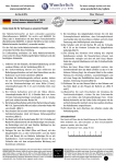
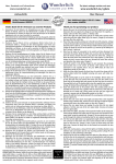
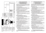
1
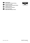
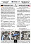
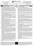
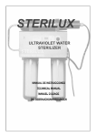
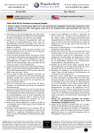
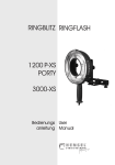
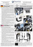
News, Downloads und Informationen
The latest catalogue sections and news
www.wunderlich.de
www.wunderlich.de/update
Anbauhilfe
User Manual
Artikel: Xenon Fernlicht K 1200 R
Bestellnummer: 8600592
See English instructions on page 2
Vielen Dank für Ihr Vertrauen zu unserem Produkt
9. Entfernen Sie die Schraube des Lenkungsdämpfer und
verschrauben Sie mit Hilfe der Inbusschraube M8 X 35 und
U- Scheibe den Halter des Steuergerätes mit 19Nm. Die
beiliegende Stahlbuchse kommt dabei zwischen Halter und
Aufnahme Lenkungsdämpfer. Zwischen den Luftfilterkasten
und Aufnahme einen Streifen Klettband kleben.(Bild F und
G)
10.Verlegen Sie nun das Lampenkabel vom Steuergerät zum
Scheinwerfer und befestigen es mit Kabelbin- dern.
11.Das Steuerkabel (Grau/ Gelb) des Zusatzscheinwerfers
wird an das weiße Kabel des original Kabelbaumes für das
Fernlicht angeschlossen. Öffnen Sie dazu vorsichtig den
Kabelstrang, welcher vom Haupt- scheinwerfer auf der
linken Seite verläuft.
12.Dazu den Schnellverbinder über das Kabel schieben so,
das er in der hinteren Führung liegt, das grau/gelbe Kabel
in die vordere Führung bis Anschlag schieben, zusammen
klappen und mit einer Zange das Metallblätchen durch den
Verbinder drücken, Sicherung einrasten.(Bild H)
13.Schliessen Sie nun das rote Kabel an den Pluspol, das braune
Kabel an den Minuspol der Batterie an. Nichtbenötigtes
Kabel können Sie mit entsprechenden Werkzeug und
Kenntnissen einkürzen, oder in einer Schlaufe am Fahrzeug
befestigen.(Bild I)
14.Nach Einschalten der Zündung und Starten des Fahrzeuges
überprüfen Sie bitte die Funktionstüchtig- keit des
Scheinwerfers, richten ihn aus und drehen alle Schrauben
fest.
15.Montieren Sie wieder alle Verkleidungsteile und kontrollieren
Sie die Funktion aller Bauteile.
Der Xenon-Scheinwerfer ist zur optimalen Ausleuchtung für
links lieferbar. E-geprüft (nicht eintragungspflichtig). Ideal
in Kombination mit dem Nebel-Zusatzscheinwerfer, Bestellnummer 8600591 (gleiche Optik).
Die Scheinwerfer werden in Kombination mit den Fernscheinwerfer
angeschlossen. Das bedeutet, dass sich der Xenonscheinwerfer
gleichzeitig bei Betätigung des Fernscheinwerfers einschaltet.
Im Lieferumfang enthalten: Ein Hella Lampen Kit, alle erforderlichen Anbauteile und ein zusätzliches Wunderlich Anbaukit,
um die Zusatzscheinwerfer an Ihrem Motorrad befestigen zu
können.
1. Entfernen Sie die Sitzbank, die Batterieabdeckung und die
vorderen Blinker mit der Verkleidung.(Bild A)
2. Die Tankverkleidung können Sie nach entfernen der
Befestigungsschrauben und nach dem Herauslösen aus den
Haltenasen nach hinten abnehmen (Bild B)
3. Nachdem die Verkleidungsteile entfernt wurden, drehen
Sie die Scheinwerferträgerbefestigung heraus, daran
wird der Scheinwerferträger mit einer Hülse (11mm),
Linsenkopfschraube M6 X 45 und U- Scheibe klein lose
befestigt.
4. Die hintere Aufnahme wird mit der Hülse (8mm),
Linsenkopfschraube M6 X 25, U-Scheibe klein von innen
mit dem Instrumententräger verschraubt, mit U- Scheibe
groß und selbstsichernder Mutter M6.
5. Die Scheinwerferaufnahme wird mit der flachen Inbusschraube
M8 X 16, Spannscheibe M8 und selbst sichernder Mutter M8
verschraubt. (Bild C)
6. Verschrauben Sie lose den Scheinwerfer mit den originalen
Sechskantschrauben (sind mit blauen Sicherungsmittel
versehen).(Bild D)
7. Das Relais wird mit der Senkschraube M5 X 10, U- Scheibe
und Mutter M5 selbstsichernd mit dem Relais- träger
verschraubt, der Relaisträger wird mit zwei Streifen
Klettband an der Steuereinheit befestigt. (Bild E)
8. Verschrauben Sie das Steuergerät des Xenonscheinwerfers
mit Hilfe der Senkkopfschrauben M5 X 10, U- Scheibe und
selbstsichernder Mutter. Achten Sie darauf die Schrauben
in die Ausfräsung einzupassen.
Genereller Hinweis: Unsere Anleitungen sind nach bestem Wissen erstellt worden,
erfolgen jedoch ohne Gewähr. Sollten Sie mit dem Anbau nicht zurecht kommen
oder Zweifel haben, so wenden Sie sich bitte an Ihren BMW-Händler oder die
Werkstatt Ihres Vertrauens. Bitte beachten Sie , dass wir keine Gewährleistungen
für fahrzeugspezifische Toleranzen übernehmen können! Es kann im Einzelfall
notwendig sein, dass Produkte diesen angepasst werden müssen.
Schraubenlineal
Das Lineal soll Ihnen bei der Identifizierung der Schrauben helfen.
Bitte bedenken Sie, daß Schrauben an Ihrer Einschraubtiefe
gemessen werden, also ohne Kopf.
Beispiel: M4x25 = Durchmesser 5 mm, Länge 25 mm
Copyright
by
Wunderlich
General note: Our fittings instructions are written to the best of our knowledge
but specifications or details may change. If you have difficulties or have doubts
with fitting this part please seek advice from your BMW dealer or workshop of
your choice. Please note that in some cases due to vehicle related tolerances
beyond our control some products might need adjusting to fit.
1
We cannot warranty parts fitting in those circumstances.
News, Downloads und Informationen
The latest catalogue sections and news
www.wunderlich.de
www.wunderlich.de/update
Anbauhilfe
User Manual
Artikel: Xenon High Beam K 1200 R
Part number: 8600592
Deutsche Anleitung auf Seite 1
Thank you for purchasing our product.
This light is designed to mount on the left side of the K1200 R, seen
in relation to direction of travel. The kit consists of the Hella lamp
kit that includes some hardware and the supplemental Wunderlich
kit which makes it possible to install the light on your specific
motorcycle. The light will be tied to your existing high beam. That
is to say that when you switch you high beam on, the Xenon light
will also switch on as a supplement. Should you wish to add an
external switch, you may do so however that is beyond the scope
of this kit. This light should be installed by someone who, ideally,
possesses intermediate technical skills. Otherwise please seek advice
from your BMW dealer or workshop of your choice. To install, please
follow these instructions:
10. Route the cable from the light ballast to the Xenon light and
secure it with cable ties.
11. The wiring harness must now be attached. Lay out the harness
and place the connectors in the vicinity of the connection points
as described in the following steps. Then re-read the following
step and make the connections in the order described. Excess
length of cable can be rolled up and secured with cable ties or,
preferably, shortened, if you possess the required skills and tools.
Once you are happy with the routing of the harness, secure in
strategic locations with cable ties.
12. The control wire (Grey / Yellow) will attach to the white wire of
the original wiring harness, using the supplied clip connector.
The white wire is to be found in the harness leading to the high
beam, located on the left side. Carefully open the harness to
expose the white wire and make the connection. This will be
accomplished by placing the connector over the white wire, such
that the wire runs through the inner channel. The control wire
(Grey / Yellow) should be pushed fully into the outer channel.
With pliers, press the metal clip into the connector and then
snap the cap closed (Image H). When finished, wrap the harness
with electrical tape.
13. Disconnect the negative (-) terminal of the battery and then
disconnect the positive (+) terminal of the battery. Attach the
red wire to the positive terminal and the brown wire to the
negative terminal (Image I). Excess length of cable can be rolled
up and secured with cable ties or, preferably, shortened, if you
possess the required skills and tools
14. Turn on the ignition and start the bike. Check the function
of the light and then adjust the position (aim). Tighten all
fasteners.
15. Reinstall all parts that were removed during installation and
always, double check your work before riding.
1. Remove the seat, battery compartment cover and the front turn
signals, together with the plastic side coverings. (Image A)
2. Remove the fuel tank covering. To accomplish this, remove the
attachment screws and then gently pull the panel towards the
rear, to disengage the holding tabs. (Image B)
3. After the covering parts have been removed, unscrew the
headlight carrier attachment bolt. The auxiliary light carrier will
attach here with a 6 X 45mm bolt, a flat washer and an 11mm
bushing. Attach the bracket but leave the bolt loose for now.
4. The rear mounting of the auxiliary light carrier attaches to the
instrument carrier, using a 6 X 25mm bolt with a small flat washer
inserted from the inside-out, an 8mm bushing and then secured
with a large flat washer and lock nut.
5. The aluminum auxiliary light bracket can now be attached to the
carrier using the 8 X 16mm bolt, 8mm tension washer and lock
nut. (Image C) (The steel bracket which may be included with
the Hella kit is not needed)
6. Loosely attach the auxiliary light to the bracket using the screws
supplied with the Hella kit. These screws can be easily identified
as they have blue thread locking fluid pre-applied. (Image D)
7. Cut the supplied Vecro strip into three equal pieces. The relay
(attached to the wiring harness) can now be attached to the relay
carrier, using a counter sunk 5 X 10mm screw, flat washer and
lock nut. Then relay carrier is then attached the Fuel Injection
control unit using two strips of the supplied Velcro. (Image E)
(the third strip of Velcro is used later in the assembly process)
8. Attach the Xenon light ballast system to the supplied carrier
bracket using 5 X 10mm counter sunk screws, flat washers and
lock nuts. Ensure that the screws fit properly into the counter
sunk holes.
9. Remove the attachment screw of the steering damper. The light
ballast assembly will be attached here. Place a strip of the
supplied Velcro to the back of the carrier bracket and attach the
assembly using the supplied 8 X 35mm bolt, steel bushing and
a flat washer. The remaining Velcro strip will stick to the air box
and provide additional support. Tighten the bolt to 19NM (14
Ft/Lb). (Images F & G)
Genereller Hinweis: Unsere Anleitungen sind nach bestem Wissen erstellt worden,
erfolgen jedoch ohne Gewähr. Sollten Sie mit dem Anbau nicht zurecht kommen
oder Zweifel haben, so wenden Sie sich bitte an Ihren BMW-Händler oder die
Werkstatt Ihres Vertrauens. Bitte beachten Sie , dass wir keine Gewährleistungen
für fahrzeugspezifische Toleranzen übernehmen können! Es kann im Einzelfall
notwendig sein, dass Produkte diesen angepasst werden müssen.
Metric Ruler for determining bolt sizes.
When measuring bolts, only measure the length of thread and shaft
without the bolt head. For example, M5x12 means diameter of bolt
is 5 mm, length 12 mm.
Copyright
by
Wunderlich
General note: Our fittings instructions are written to the best of our knowledge
but specifications or details may change. If you have difficulties or have doubts
with fitting this part please seek advice from your BMW dealer or workshop of
your choice. Please note that in some cases due to vehicle related tolerances
beyond our control some products might need adjusting to fit.
2
We cannot warranty parts fitting in those circumstances.
News, Downloads und Informationen
The latest catalogue sections and news
www.wunderlich.de
www.wunderlich.de/update
Anbauhilfe
User Manual
Artikel: Xenon Fernlicht K 1200 R
Bestellnummer: 8600592
Artikel: Xenon High Beam K 1200 R
Part number: 8600592
A
B
C
D
E
F
G
H
I
Genereller Hinweis: Unsere Anleitungen sind nach bestem Wissen erstellt worden,
erfolgen jedoch ohne Gewähr. Sollten Sie mit dem Anbau nicht zurecht kommen
oder Zweifel haben, so wenden Sie sich bitte an Ihren BMW-Händler oder die
Werkstatt Ihres Vertrauens. Bitte beachten Sie , dass wir keine Gewährleistungen
für fahrzeugspezifische Toleranzen übernehmen können! Es kann im Einzelfall
notwendig sein, dass Produkte diesen angepasst werden müssen.
Copyright
by
Wunderlich
General note: Our fittings instructions are written to the best of our knowledge
but specifications or details may change. If you have difficulties or have doubts
with fitting this part please seek advice from your BMW dealer or workshop of
your choice. Please note that in some cases due to vehicle related tolerances
beyond our control some products might need adjusting to fit.
3
We cannot warranty parts fitting in those circumstances.