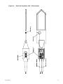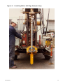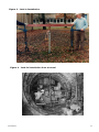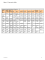
1
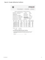
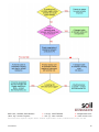
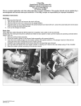
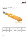
Vibrating Wire Push-In Pressure Cell/Piezometer User Manual Man 157 3.0.2 06/08/2018 Phillip Day Andy Small Chris Rasmussen Manual No. Revision Date Originator Checked Authorised for Issue User Manual 1 Contents Section 1 : 1.01 1.02 Introduction .................................................................................................. 3 Description of Equipment .................................................................................. 3 Applications ..................................................................................................... 3 Section 2 : 2.01 2.02 2.03 Preparation of the Equipment ........................................................................ 4 Checking for correct operation ........................................................................... 4 De-airing the Piezometer ................................................................................... 4 Zero Check and Calibration................................................................................ 4 Section 3 : 3.01 3.02 3.03 3.04 Installation of the Pressure Cell/Piezometer ................................................. 5 Drilling the borehole ......................................................................................... 5 Vertical Hole (Permanent installing pipes & recoverable cell) .................................. 5 Horizontal Hole ................................................................................................ 6 Vertical Hole (Recoverable installing pipes & permanent installation) ...................... 6 Section 4 : Frequency of Observations ............................................................................ 7 Section 5 : Data Interpretation ....................................................................................... 8 5.01 5.02 5.03 Pressure Measurements .................................................................................... 8 Pore Pressure .................................................................................................. 8 Data Reduction ................................................................................................ 8 Figure Figure Figure Figure Figure Figure Figure Figure 1 - Push-In Pressure Cell / Piezometer ............................................................... 11 2 - Installing With a Drill Rig (Example Only) ...................................................... 12 3 - Jack-in Installation ......................................................................................... 13 4 - Jack-In Installation from a tunnel ................................................................... 13 5 - Hydraulic Jack-in Installation.......................................................................... 14 6 - Typical Time - Vs – Total Stress Chart ............................................................. 15 7 - Conversion Table............................................................................................. 16 10 - EU Declaration of Conformity ........................................................................ 18 Appendix A. User Manual Troubleshooting Guide .............................................................................. 19 2 Section 1 : Introduction 1.01 Description of Equipment The Push-In Pressure Cell consists of a pointed rectangular spade shaped oil filled chamber formed from two sheets of steel welded around the edge. The dimensions of the active part of the pressure cell are approximately 100 x 200mm by 6.4mm thick. The oil filled cell is connected by a short length of steel tube to a Vibrating Wire Transducer, thus forming a sealed hydraulic system. The cell is welded to a support plate and connector boss onto which the installation pipes are attached. A porous filter disc is incorporated in the support plate and is connected to a second Vibrating Wire Transducer thus providing an integral piezometer. The two Vibrating Wire Transducers are mounted in parallel behind the spade-cell and are protected within the protective pipe. Each transducer is fitted with PVC sheathed, screened, electrical cable which extends beyond the top of the borehole to enable future termination or extensions. 1.02 Applications The Push-In Pressure Cell/piezometer is suitable for measuring total earth pressures in clay soils up to shear strength of approximately 300 kN/m. The incorporation of a Vibrating Wire Piezometer in the instrument enables pore water pressure to be measured and therefore the effective stress can be determined. The cells can also be installed permanently and used to monitor changes in earth pressure associated with, for example, construction of an excavation. When installed in vertical boreholes total horizontal stresses are measured by the pressure cell. They are often installed in stiff clay behind and in front of retaining walls, in soft puddle clay cores of old embankment dams and in glacial till adjacent to sea cliffs. The cells have also been installed in horizontally drilled boreholes from tunnels and cliff faces. In these situations both horizontal and vertical stresses can be measured by the appropriate orientation of a number of cells. The cells may be used as a site investigation tool to measure the in-situ stresses in the ground prior to any disturbance. In this case the cells need only be left in for a few weeks. User Manual 3 Section 2 : Preparation of the Equipment 2.01 Checking for correct operation This is achieved by connecting the pressure cell and piezometer to the Vibrating Wire Readout/Logger and taking a set of readings in F2/1000 Units. The readings on the pressure cell should be stable. See the Vibrating Wire Readout/Logger operating manual operating details. 2.02 De-airing the Piezometer Refer to Figure 1 Unscrew the double coupling to reveal bleed screw A. Remove bleed screws A and B. Place the pressure cell/piezometer vertically (point facing downwards) in a water filled container to immerse the filter and leave for at least 24 hours. Incline the pressure cell/piezometer at approximately 30° from horizontal with the tip pointing upwards. Fill dosing syringe with deaired water and attach it to bleed screw A. Inject water until it trickles out of bleed point B. Turn the pressure cell/piezometer vertically (point facing upwards) and shake vigorously to displace any air which may be trapped near the diaphragm of the piezometer transducer. Inject water to displace entrapped air, insert and tighten bleed screw B (check beforehand that O-ring is still fitted to bleed screw). Lay the pressure cell/piezometer horizontally, disconnect dosing syringe and insert and tighten bleed screw A. Store the pressure cell/piezometer under water to keep the ceramic filter fully saturated until time of installation. 2.03 Zero Check and Calibration Calibration values for the pressure cell and piezometer transducers are supplied by the factory. The pre-set base is the fluid pressure in the oil within the pressure cell. The pre-set base is affected by ambient temperature and barometric pressure thus this should be borne in mind when checking the base. Prior to installation of the cells it is vital to record the Base Reading (or site Zero), since it will be the value to which all others will be compared. Place the cell in an area where a constant temperature exists. A good option is to place the cell in a drum full of water. However the constant temperature should be as close to the ground temperature as possible, since the oil filled cell will be affected by thermal expansion. When the temperature gradients that can exist in the cell have been removed (3 or 4 hours perhaps) reading on the 2 transducers should be recorded in a “Period” format. The readings should be noted on the calibration sheet supplied by the factory. See the Vibrating Wire Readout/Logger operating manual for operating details. User Manual 4 Section 3 : Installation of the Pressure Cell/Piezometer 3.01 Drilling the borehole The borehole into which the pressure cell is installed should be at least 100mm diameter, but preferably 150mm diameter. It should be drilled to within 0.5m to 1.0m of where the cell is to be installed. The method of drilling e.g. shell and auger, rotary or hand augering should ensure that the borehole stays open. Casing may be required to prevent the borehole collapsing in poor ground. 3.02 Vertical Hole (Permanent installing pipes & recoverable cell) Having drilled the borehole and prepared the instrument, installation can now take place. Remove the 500mm long protective pipe and feed the cables through the first length of the installing pipe and screw the pipe onto the double coupling at the pressure cell/piezometer. A thread sealing compound such as Boss White or PTFE Tape should be put onto the coupling to prevent water coming up inside the installing pipe. Bentonite pellets and water can also be put down the inside the first 0.5m of the installing pipe, again to seal the pipe. Sealing the installation pipe prevents it from acting as a drain and ensures a fast response of the piezometer to changes in the pore water pressure in the soil. A mark on the upper end of the first installation pipe should be made to indicate the orientation of the pressure cell. It is essential to mark the subsequent installation pipes to ensure the correct orientation of the pressure cell is maintained. Lower the pressure cell and first length of installing pipe down the borehole and support it. Connect subsequent lengths of installing pipe making sure the orientation is maintained. When installing pressure cells to depths greater than about 6m the weight of the installing pipes necessitates the use of a pipe clamp to hold the lower pipes while screwing on the next one. An arrangement for lowering the pressure cell and pipes such as an overhead pulley system, is also required. WARNING Before the pressure cell/piezometer is lowered below water in the borehole or is pushed into the ground a zero reading on the pressure cell and piezometer must be taken. This reading is necessary since the pressure cell is temperature sensitive and the temperature at the surface may well be different to that in the ground. This reading then becomes the zero reading which is used in all subsequent calculations. Having taken the zero reading with the pressure cell/piezometer down the borehole and lowered it to the bottom of the borehole, the cell is advanced such that the centre of the active part of the cell is at least 0.5m below the bottom of the borehole. Before pushing the pressure cell/piezometer, ensure the push-in adaptor and the cap is connected on the upper end of the installation pipes to allow the cables to come out of the pipes and to allow the pushing load to be applied to the installation pipes. The force required to install the pressure cell/piezometer 0.5 - 1m beyond the end of the borehole in a clay having a shear strength of approximately 150 mN/m is between about 1.5 and 2 tonnes. Most of the reaction required, however, is to push the boss of the cell and the installation pipes into the ground. Various methods of pushing the pressure cells/piezometer into position have been used. The cell needs to be pushed in steadily. Often the drill used to bore the hole can be used to apply the necessary pushing force. Such an arrangement is shown in Figure 2. If the drilling rig is not suitable i.e. a shell and auger rig, or if the borehole was hand augered the arrangement shown in Figure 3 could be used. This consists of a cross beam, which is anchored to ground pickets via two pull lifts. User Manual 5 3.03 Horizontal Hole Installation procedure for horizontal holes is much the same as for vertical holes, however the problem of supporting the weight of the installation pipes does not exist. The arrangement for pushing the pressure cell/piezometer into position will depend upon the circumstances. Two arrangements for pushing the pressure cell/piezometer into position in horizontal boreholes are shown in Figures 4 and 5. In Figure 4 the pressure cell/piezometer is being installed from a 5 metre diameter bored tunnel into London clay at a depth of 9.3m. The borehole was hand augured and had a diameter of 100mm. The pressure cell/piezometer was pushed into position using an 8 tonne capacity double acting hydraulic jack fixed to an Acrow prop. Reaction for the jack was provided by the opposite wall of the tunnel. Using this arrangement the one pressure cell was pushed up to 2m beyond the end borehole generating a maximum thrust of 3.5 tonnes. In Figure 5 the pressure cell/piezometer is being pushed into the side of a sea cliff of glacial till. 3.04 Vertical Hole (Recoverable installing pipes & permanent installation) To enable recovery of the installing pipes, the pressure cell/piezometer is supplied with a 500mm long protective pipe with a left-handed thread at its upper end. A re-usable adaptor (threaded left-hand and right-hand – this must be ordered separately) connects the extension pipe to the installing pipes. Installation of the pressure cell/piezometer is generally as described in 3.20. After the pressure cell/piezometer has been pushed in, the installing pipes are turned in a clockwise direction until the adaptor disconnects at the extension pipe. User Manual 6 Section 4 : Frequency of Observations Observations on the pressure cell/piezometer should be taken very soon after installation even before grouting has been carried out (minutes rather than hours). Several readings should be taken during the first day and a reading every day for the subsequent 3 to 4 days. A reasonable number of readings during the first 10 days after installation will ensure the pressure cell is functioning properly in the short term and provide a typical pressure/time dissipation curve (see Figure 6). The frequency of observations in the long term will depend on the reason for the installation. If only a knowledge of the in-situ stresses is required and no changes are expected then weekly readings for about a month after the first 10 days will probably be sufficient. The cell could be removed and installed elsewhere. On removing a cell it is important to check that the initial pre-set zero is the same as that on installation. Where pressure cells have been installed permanently to monitor changes in earth pressure such as adjacent to a retaining wall frequency of readings will depend on the construction operations. Frequent readings between construction operations will give confidence in the observations. User Manual 7 Section 5 : Data Interpretation 5.01 Pressure Measurements Original In-Situ Pressures The action of pushing the pressure cell/piezometer into the ground initially generates high pressures locally around the cell. In a clay soil these excess pressures dissipate rapidly at first, but it is usually about 10 days after installation before the cell registers a stable equilibrium value. Due to the method of installation this value is likely to be larger than the original in-situ pressures in the undisturbed ground. It is suggested that where the pressure cell/piezometer is pushed into soft and very soft clays the magnitude of the over-read is very small and may be ignored. However in firm and stiff clays it appears that it over-reads by a small but significant amount. Based on work by Tedd and Charles (1983), it is suggested that the over-read should be taken as half the undrained shear strength of the clay. Pressure Changes Pressure changes measured by Push-In Pressure Cell/piezometers appear to be sensible and agree with other methods of measuring pressure in clay soils. (Tedd et al 1984, 1985). Measured changes of pressure should therefore be regarded as actual changes without any correction being applied. 5.02 Pore Pressure Observations from the piezometers generally give reliable and sensible results. It can take up to a week before reliable results are obtained. 5.03 Data Reduction The mathematical relationship between the frequency of vibration of a tensioned wire and the force applying the tension is an approximate straight line relationship between the square of the measured frequency and the applied force. Engineering units of measurement maybe derived from the frequency-based units measured by vibrating wire readouts, in 3 traditional ways:From ‘Period’ units and from ‘Linear’ (f^2/1000) units using two methods: a simple Linear equation or a Polynomial equation. Calculation using ‘Period’ units The following formula is used for readings in ‘Period’ units. E = K (10^7/P0^2 – 10^7/P1^2) Where, E is the Pressure in resultant Engineering units, K is the Period Gauge Factor for units of calibration (from the calibration sheet), P0 is the Period ‘base’ or ‘zero’ reading P1 is the current Period reading. User Manual 8 This method of calculation is used by the Soil Instruments Vibrating Wire loggers’ (models RO-1-VW-1 or 2 and with serial numbers starting VL or TVL) internal processors’, for calculating and displaying directly on the loggers’ LCD screen, the required Engineering based units. The loggers’ require ‘Period’ base or zero reading units for entering into their channel tables, to calculate and display correctly the required engineering units. If an Engineering-based unit is required other than the units of calibration, then the correct K factor will have to be calculated using the standard relationship between Engineering units. For example, if the units of calculation required were in KGF/Cm2 and the calibration units were kPa, we can find out that 1kPa is equal to 0.01019 KGF/Cm 2, so we would derive the K factor for KGF/Cm2 by multiplying the K factor for kPa by 0.01019 Please see conversion factors Figure 7. Calculation using Linear units The following formula is used for readings in ‘Linear’ units. E = G (R0 – R1) Where, E is the resultant Engineering unit, G the linear Gauge factor for the units of calibration (from the calibration sheet), R0 is the Linear ‘base’ or ‘zero’ reading R1 is the current Linear reading. Again the Linear gauge factor for units other than the units of calibration would need to be calculated using the same principles as stated in the last paragraph of the ‘Period unit’ section. Linear unit calculation using a Polynomial equation Linear units maybe applied to the following polynomial equation, for calculation of Engineering units to a higher order of accuracy. E = AR1^2 + BR1 + C Where, E is the resultant Engineering unit, A, B and C the Polynomial Gauge factors A, B and C, from the instrument’s calibration sheet, R1 is the current Linear reading. The value C is an offset value and relates to the atmospheric pressure experienced by the pressure cell at the time of calibration. This figure will have changed at the time of installation due to changes in altitude or barometric pressure, so C should be re-calculated at the installation time as follows: C = - (AR0^2 + BR0) Where, A and B are as above, User Manual 9 R0 is the Linear ‘base’ or ‘zero’ reading. Please note that the sign of the re-calculated value of C, should be the same as the original value of C, so if the original is negative then the recalculated value should also be negative. Conversion to engineering units other than the units of calibration, would best be done after conversion, using a factor calculated using the same principles as stated in the last paragraph of the ‘Period unit’ section. Please see conversion factors in Figure 7. User Manual 10 Figure 1 - Push-In Pressure Cell / Piezometer User Manual 11 Figure 2 - Installing With a Drill Rig (Example Only) User Manual 12 Figure 3 - Jack-in Installation Figure 4 - Jack-In Installation from a tunnel User Manual 13 Figure 5 - Hydraulic Jack-in Installation User Manual 14 Figure 6 - Typical Time - Vs – Total Stress Chart Dissipation of earth pressures measured by push-in spade pressure cells in London Clay (after Tedd and Charles, 1983). User Manual 15 Figure 7 - Conversion Table Pressure, Stress & Modulus of Elasticity MN/m2 kp or kN/m2 atm or kgf/cm bar or kPa 2 MPa 1 1000 10.197 10.000 9.869 1.019 x 9.87 x 0.001 1 0.0100 -2 10 10-3 9.807 x 98.07 1 0.9807 0.9678 10-2 0.100 100.0 1.0197 1 0.9869 0.1013 101.33 1.0332 1.0132 1 9.788 x 9.983 x 9.789 x 9.661 x 9.7885 10-3 10-2 10-2 10-2 2.983 x 3.043 x 2.984 x 2.945 x 2.9835 10-3 10-2 10-2 10-2 1.333 x 1.3595 1.333 x 1.315 x 0.1333 -4 10 x 10-3 10-3 10-3 0.1073 107.3 1.0942 1.0730 1.0589 6.895 x 7.031 x 6.895 x 6.805 x 6.895 -3 10 10-2 10-2 10-2 4.788 x 4.788 x 4.883 x 4.788 x 4.725 x 10-5 10-2 10-4 10-4 10-4 User Manual m H2O ft H2O mm Hg tonf/ft2 psi or lbf/in2 lbf/ft2 102.2 7500.6 9.320 145.04 20886 0.1022 0.3352 7.5006 0.0093 0.14504 20.886 10.017 32.866 735.56 0.9139 14.223 2048.1 10.215 33.515 10.351 33.959 750.06 760.02 14.504 14.696 2088.6 2116.2 1 73.424 0.9320 0.9444 9.124 x 10⁻² 2.781 x 10⁻² 1.243 x 10⁻³ 1 6.426 x 10⁻² 4.464 x 10⁻⁴ 1.4198 204.45 335.2 3.2808 0.3048 1 1.362 x 4.469 x 10-2 10-2 10.960 35.960 22.377 1 804.78 0.7043 2.3108 51.714 4.891 x 1.605 x 10-3 10-2 0.3591 0.43275 62.316 1.934 x 10⁻² 15.562 2.7846 2240.0 1 144.00 6.944 x 10⁻³ 1 16 Figure 8 - Sample Calibration Certificate User Manual 17 Figure 10 - EU Declaration of Conformity User Manual 18 Appendix A. Troubleshooting Guide If a failure of any vibrating wire transducer or the electrical cable is suspected, the following steps can be followed. The transducers themselves are sealed and cannot be opened for inspection. The “Troubleshooting Flowchart” should also be followed if any instrument failures are suspected. The steps below and the Troubleshooting Flowchart are applicable generally to any vibrating wire instrument. STEP 1 Before any of the following steps are followed, the portable data logger should be used to verify the stability of the reading and the audio signal from the portable logger should be heard. An unstable (wildly fluctuating) reading from a transducer or an unsteady audio signal are both indications of possible problems with instruments or their related electrical cables. If a portable data logger is giving faulty readings or audio signals from all transducers, a faulty readout unit must be suspected. Another readout unit should be used to check the readings from the transducers and Soil Instruments should be consulted about the faulty readout unit. STEP 2 The resistance across the two conductors of the electrical cable should be checked. This can be done using a multimeter device across the two exposed conductors if the cable has not been connected to a terminal cabinet, or can be done just as easily across the two conductors if the instrument has been connected to such a terminal (or datalogger). The resistance across the two conductors should be approximately of the order of 120 to 180. The majority of this resistance will come from the transducer (say approximately 130). Before proceeding to Steps 3 and 4, the continuity should be checked between conductors and earthing screen of the electrical cable. If continuity exists, a damaged cable is confirmed. STEP 3 If the resistance across the two conductors is much higher than the values quoted in “STEP 1” (or is infinite), a severed cable must be suspected. STEP 4 If the resistance across the two conductors is much lower than the values quoted in “STEP 1” (say 80 or less) it is likely that cable damage has occurred causing a short in the circuit. STEP 5 If the resistance is within the values quoted in “STEP 1” (i.e. 120 to 180), AND no continuity exists between conductor and earth screen and on checking the reading from the transducer, it proves to be still unstable or wildly fluctuating, it must be assumed that the integrity of the circuit is good. A faulty transducer could be suspected if neighbouring construction activities do not account for the anomaly Soil Instruments should be consulted. If the point at which the cable is damaged is found, the cable can then be spliced in accordance with recommended procedures. User Manual 19 R less than 80 Bell Lane, Uckfield, East Sussex t: +44 (0) 1825 765044 e: [email protected] TN22 1QL United Kingdom f: +44 (0) 1825 744398 w: www.itmsoil.com Soil Instruments Ltd. Registered in England. Number: 07960087. Registered Office: 5th Floor, 24 Old Bond Street, London, W1S 4AW User Manual 20