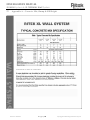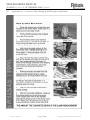
1
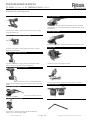
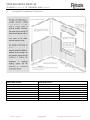
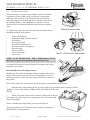
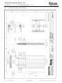
INSTALLATION MANUAL
XL WALL System & XL THERMAL Wall System
INSTALLATION MANUAL
XL Wall System & XL Thermal Wall System
Revision 2010.01
P a g e |1
Copyright © Building Solutions Pty Ltd
INSTALLATION MANUAL
XL WALL System & XL THERMAL Wall System
Contents:
1.
Tools and Equipment
2.
Considerations prior to construction
3.
Applicable Installation Standards
4.
XL Wall, XL Thermal Wall System Standard Components
5.
Handling of Panels
6.
Panel installation
7.
Wall Straightening
8.
Corner Installation
9.
Tee Junction Installation
10.
Closing Wall Ends
11.
Fixing Sill & Lintel Panels
12.
Fire Door Installation
13.
Control & Construction Joint Installation
14.
External Wall & Slab detail
15.
Concrete Filling
16.
Concrete Pump Equipment
17.
Concrete Quality Control
18.
Concrete Mix Design
19.
Crew Size
20.
Concrete Pour/Fill Height
21.
Pre Pour Checklists
22.
Concrete Filling Method
23.
Post Pour Checklist
24.
Health and Safety
25.
Certified Panel Brace
26.
Certified Panel Lifting
27.
Appendix A – Concrete Mix, Slump & Pour/Fill Height
This manual and contents are copyright and must not be reproduced without the permission of Building Solutions Pty Ltd. This manual is subject
to regular updates, check you have the latest version by contacting Building Solutions on 1300 929 782 or email [email protected].
The design of the wall system for a building or application requires the services of professional consultants. This information has been prepared
as a source of information to provide general guidance to professional consultants and no way replaces the services of professional consultants.
No liability can therefore be accepted by Building Solutions Pty Ltd for its use.
Manual Version 2010.01
Revision 2010.01
P a g e |2
Copyright © Building Solutions Pty Ltd
INSTALLATION MANUAL
XL WALL System & XL THERMAL Wall System
1.
Tools and Equipment
Tools and Equipment required by a 3-person installation crew:
• Rotary Hammer Drill with corresponding drill bits
• Dustless 5 in (125mm) angle grinder with diamond cutting blade.
• 9 in (230mm) angle grinder with metal cutting blade, Diamond grinding disc, and diamond cutting
blade.
• Explosive tool for fixing to floor.
• Fibre shears
• Tool belt, hammer, chisel, all purpose tin snips, stanley knife, marking crayon, pencils, steel fixing nips,
set square
• Circular saw suitable for cutting fibre cement / aluminium combination.
• Circular saw suited for timber.
• 3 impact screw battery drills (14 V+ preferably 18V).
• Chemset / epoxy equipment if starter bars not cast in place.
• Compressor with hose and air gun (to clear dust from starter bar holes if starters are chemset in place).
• Measuring tapes (8m and 30m)
• Chalk line and string line.
• Spirit Level (2m)
• 500 x 500 roofing square
• Step Ladders
• Junction box with earth leakage safety switch.
• 2 saw horses or a bench
• 4 extension leads
• Safety equipment – boots, hard hat, sun protection, eye protection, ear protection and dust masks
• Panel braces. Appropriately-engineered braces to support walls during construction and pouring.
• 4m Straight Edge
• Pinch Bar
• Finishing Trowel for window sills
• Sponge and bucket for wiping down door frames after pour
• A compound saw for cutting aluminium sections (mitre and 90 degrees)
• Dry Vacuum cleaner
Screws and Fixings Required and Supplied by Installer
•
•
•
•
•
•
For fixing a certified panel brace to the panel use 3 off 14-10 x 42 mm HEX TEK screws (Fig A)
For fixing a certified panel bracing to the slab use 1 off 10mm x 60mm concrete screw bolt (Fig B)
For general panel fixings use 8-18 x 25 CSK SELF-EMBED TEK CLASS 3 GALV (Fig C)
Ribbed Head or Winged Tip TEK point self tapping screws at 300 centres
For fixing the Bottom Plate Assembly to the slab use 20mm collated masonry nails
For packing between the XL Wall Rebated Top Track extrusion and Rebated Bottom Track extrusion
use 5mm packers typically utilised in glazing (e.g. G. James 5mm packers)
For fixing XL Thermal Wall Panel Joiner Insulation Inserts and Internal Corner Insulation Inserts use
100 x 3.75 GALV Flat Head Nails
Fig A
Revision 2010.01
Fig B
P a g e |3
Fig C
Copyright © Building Solutions Pty Ltd
INSTALLATION MANUAL
XL WALL System & XL THERMAL Wall System
Standard Tools Required
GX 120 gas system with 40 nail magazine
7 Inch Angle Grinder
The above tool is used for cutting or grinding where needed. A diamond
cutting blade can be incorporated for cutting a combination of fibre cement
and aluminium.
The above tool or similar is suitable for fastening bottom track assembly
5 Inch Angle Grinder
to slab with masonry pins.
Makita 24v Cordless Rotary hammer drill
The above tool or similar is used for trimming and cutting panels if needed
The above tool or similar is used to prepare holes ready for a 10mm x
Circular Saw
60mm Concrete Screw Bolt.
SIW 144-A cordless impact wrench
The above tool or similar is used to secure the certified brace with an
Circular saw is used to trip form ply if needed.
10mm x 60mm Concrete Screw Bolt to the finished slab.
Compound Saw
SID 144-A cordless impact screwdriver
The above tool or similar is used to fix the 8g x 25 CSK Ribbed Head (or
Winged Tip) Tek Point Self Tapping Screws and the 6.5mm x 40 mm Tek
screws.
The above tool is used for cutting the aluminium section (mitre and 90º).
Hand Tools Required
DG 150 diamond grinder
The above tool or similar is used to grind out any imperfections after the
installation is completed
VCD 50 dry vacuum cleaner
Roofing Square
The unit above or similar is connected to the DG 150 Diamond
Grinder to extract the dust whilst grinding.
Revision 2010.01
P a g e |4
Copyright © Building Solutions Pty Ltd
INSTALLATION MANUAL
XL WALL System & XL THERMAL Wall System
2.
Considerations Prior to Construction
1. A work method statement should be completed by the panel installation contractor and signed off
prior to onsite work commencing.
2. An accurate Layout grid must be provided by the builder before wall bottom plate assembly are
positioned. It is suggested that a surveyor mark out the slab to the architectural plans with
surveying pins. It is imperative that there are pins at the start of wall, the end of wall, and at every
directional change.
3. Set out the slab using a chalk line and workshop drawings supplied.
Check set out with a string line to ensure the marked chalk line is
correct. In this process it is also recommended that the distance
between pins be measured and those measurements be checked with
the workshop drawings.
For increase speed of erection - with the use of workshop drawings,
mark out the slab with a marking crayon placing wall numbers and panel numbers with their
coinciding walls.
4. It is recommended, as a minimum, that slab levels meet the following:
•
Generally, the floor is to be within + or – 10mm of level over the entire room and at all
times within + or – 5mm of level over any 3m length
5. Check location of cast-in starter bars or marked position of starter bars are in accordance with the
structural engineers specification.
NOTE: For XL Thermal Wall – Starter bars to be positioned to suit the concrete core ensuring that
sufficient concrete cover is achieved (bars may need to be offset from the insulation).
6. Check set downs for correct positions.
7. Ensure that all tools are tagged and tested and in good working order.
8. Provide installation crews with the following documentation
•
Program of works
•
Relevant architectural and structural drawings
•
Window / Reveal / Opening schedule
•
Workshop Drawings
9. Co-ordinate with other trades identifying work methods.
Revision 2010.01
P a g e |5
Copyright © Building Solutions Pty Ltd
INSTALLATION MANUAL
XL WALL System & XL THERMAL Wall System
3.
Acceptable Installation Tolerances
Optional
Top Plate
DESCRIPTION
TOLERANCE
Concrete Blow Holes / Voids
Flatness
NONE
Over 1.25m Grid
At 5m over 10m
< 3m
> 3m
Wall Length / 1000mm
Stated Angle
Out of Plumb
Straightness
Corner Details
Revision 2010.01
P a g e |6
Within 5mm
Within 7mm
Within 5mm
Within 8mm
Within 3mm
+ / - 2deg
Copyright © Building Solutions Pty Ltd
INSTALLATION MANUAL
XL WALL System & XL THERMAL Wall System
4.
XL Wall & XL Thermal Wall (XL-T) System Components
Standard Track
Track Joiner / Assembly
Panel Joiner
Rebated Bottom Track
Rebated Top Track
Rebated Track Assembly
External Corner Closer
Internal Corner Closer
FC External Corner
Tee Closer
Nib End Closer
XL-T Joiner Insert
XL-T Tee Closer
XL-T External Corner
265 Nib End Closer
Revision 2010.01
P a g e |7
Copyright © Building Solutions Pty Ltd
INSTALLATION MANUAL
XL WALL System & XL THERMAL Wall System
4.1
XL Thermal Wall (Xl-T) System Insulation Components
Revision 2010.01
P a g e |8
Copyright © Building Solutions Pty Ltd
INSTALLATION MANUAL
XL WALL System & XL THERMAL Wall System
5.
Handling of Panels
General
The panels will typically arrive on site on a flat bed semi-trailer.
The pallets will be labelled clearly for identification and to assist in the
placement on slab.
A typical pallet of panels, say 2400 x 1200 x 1200 will weigh
2
approximately 864 kg based on 25 kg/m .
Handling Manually
When carrying the panels manually, hold panel using one of the plastic
stud joiners as a handle or hold underside of panel at stud-supported
sides. It is essential that the panel is not picked up at the top or bottom
corners or placed on the ground in any way that may weaken or break
the sheet in that area.
Handling Mechanically
Panels can be removed from the delivery vehicle by forklift or crane. If
the crane is to be used it is at the crane drivers discretion whether the
lifting method is acceptable.
Detailed are two recommended lifting methods that are used for unloading the Ritek® system.
In addition, approved and correctly-rated slings may be used to crane panels. Contact Ritek for further information
on the lifting tynes.
Avoid picking up panels by unprotected corners
Revision 2010.01
P a g e |9
Copyright © Building Solutions Pty Ltd
INSTALLATION MANUAL
XL WALL System & XL THERMAL Wall System
6.
Panel Installation
Set out wall positions from grid lines supplied by the head contractor. Mark locations of openings and individual
panel positions ready for the bottom plate assembly.
Note: When positioning reinforcing starter bars for the XL Thermal Wall panels, the starter bars are offset from the
centre of the wall panel due to the thickness of the panel insulation.
At corner intersections, position bottom plates so both track sections stop 30 mm short of the corner.
90º Corner Bottom Plate Set-out
T-Junction Bottom Plate Set-out
Fix Track Jointers down with masonry nails once the bottom plate is correctly positioned. Track joiners should be
fixed at 600mm centres. Masonry nails should be positioned close to each track rail. Track joiners can be slid
sideways before fixing to slab to avoid metal-to-metal contact with steel starter bars.
For long wall runs which require Track Joiners to be end-joined, locate a Track Joiner to bridge the joint between the
extrusions.
Revision 2010.01
P a g e | 10
Copyright © Building Solutions Pty Ltd
INSTALLATION MANUAL
XL WALL System & XL THERMAL Wall System
6.
Panel Installation (continued)
The installation of the panels is undertaken in the following manner, care is to be taken when inserting the panels into the bottom
track, and ensuring that the starter bars do not conflict with the studs, which can be done prior to installing the panel (ensure to
keep starter bars at engineers specifications). Always be sure to start the installation process from a corner or end of wall where
possible.
NOTE: When positioning reinforcing starter bars for XL Thermal Wall panels, the starter bars are offset from the centre of the
wall panel due to the thickness of the panel insulation.
1
2
For increased speed of panel installation fix the
panel joiners to the panel before erecting.
NOTE: For XL Thermal Panel – fix the
insulation infill and secure using the galv nails
Create jig to ensure starter bars do not conflict
with studs
4
3
Position first panel in line with surveyor’s wall
starting point.
Note: For XL Thermal Panel - ensure insulation
is to correct facing side of the panel
5
6
Panel is lifted over starter bars, slid over the
Panel Joiners of the fixed panel and then
lowered into position
Standard panel requires three people to be
placed into position.
Revision 2010.01
Secure brace foot plate to slab with Excalibur
bolt and brace to panel with self-tapping screws
into panel stud. Proceed to plumb panel in all
directions utilising the brace’s push pull
mechanisms and a level.
P a g e | 11
Copyright © Building Solutions Pty Ltd
INSTALLATION MANUAL
XL WALL System & XL THERMAL Wall System
6.
Panel Installation (continued)
Guide each face of the panel into bottom track when
lowering
Panel is then checked for level and screwed off
at 300mm centers into the rebate of the adjoining
panel.
Note: Panels over 4.2m are to be craned into position. Please adhere to the Ritek’s XL Wall single
panel lifting procedure and ensure that industry Workplace Health and Safety is followed.
7.
Wall Straightening
NOTE: Be sure to plumb
and straighten every wall
before any directional
change occurs.
Secure Tek screws at either end of wall and fix a string line between the two. Cut three lengths of electrical conduit at
the same diameter and length and place one at either end of the wall.
Ensure that both ends of the wall are plumb with a level, then move along to each panel join placing the conduit on the
face of the panel beside the rebate. Adjust the brace until the string line touches the conduit to ensure a straight surface
is achieved.
Revision 2010.01
P a g e | 12
Copyright © Building Solutions Pty Ltd
INSTALLATION MANUAL
XL WALL System & XL THERMAL Wall System
8.
Corner Installation
Set bottom plate assembly 30mm back from
internal corner to allow the corner extrusion to be
flush with the slab.
Install panels at corner ensuring they are levelled
in both directions before fixing off internal corner.
Check corner panel positioning, insuring that internal
sheets are flush but allow 2mm in each direction for
external corner to be fitted.
Proceed to fix internal corner extrusion at 450mm
centres to the stud as shown above. Ensure that all
cogged bars are inserted and all horizontal steel is in
place. At this stage the structural engineer is able to
inspect the structural steel and sign off on it
NOTE: For XL Thermal Wall – Install internal
corner insert and secure using the galv nails.
Reinforcing spacer wheels may be required to
centralise the horizontal reinforcement.
NOTE: Allow corner extrusion to run
150mm past the Finished Floor Level
(FFL) on all exterior walls that are
consecutive. Use this same process on
nib end closures and tee junctions that
are on the exterior of the building.
Insert corner extrusion and fix off at 300mm
centres ensuring the corner is plumb and square.
Revision 2010.01
P a g e | 13
Copyright © Building Solutions Pty Ltd
INSTALLATION MANUAL
XL WALL System & XL THERMAL Wall System
9.
Tee Junction Installation
Fix bottom plate assembly to set out on slab
with 20mm masonry pins.
Set out the Tee Junction to surveyors pins
Ensure panels are plumb in all directions and
screw off internal corners. Ensure that all
horizontal and vertical reinforcement has been
fixed to engineers specifications.
Place Tee Closure into position ready for
closing off
Fix a toggle (ply wood or aluminium angle) to
the tee junction bringing it flush with adjacent
panels.
Revision 2010.01
Fix toggles vertically up the tee junction to keep
it in position during the pour process
P a g e | 14
Copyright © Building Solutions Pty Ltd
INSTALLATION MANUAL
XL WALL System & XL THERMAL Wall System
10.
Closing Wall Ends
Once reinforcement has been inspected and signed off, the ends are closed.
Wall and Blade Wall Ends
An end closer section is placed over the end of the open wall and tapped into position. Screws are then fixed at 300-mm centres
through the sheeting and into stud extrusion. For 200XL, 265XL, 200XL-T and 265XL-T walls, it is recommended that hexhead screws are fixed through the aluminium end closer into the studs.
Revision 2010.01
P a g e | 15
Copyright © Building Solutions Pty Ltd
INSTALLATION MANUAL
XL WALL System & XL THERMAL Wall System
11.
Fixing Sill and Lintel Panels
Screw-fix panel joiners to either side of the lintel and the end closure to the underside.
Place sill panels into position checking for level
in all directions. Screw in place the lintel
section into the adjacent panel on some timber
packers ready for positioning.
Install adjacent panel to window opening and
fix the lintel into position utilising a Level for
precision. Screw-fix the lintel at 300mm
centres to the adjacent panels ensuring the
bottom of lintel is level.
Prop Lintel sections with timbers and/or acrow-props prior to core-fill being placed to avoid any deviation.
Revision 2010.01
P a g e | 16
Copyright © Building Solutions Pty Ltd
INSTALLATION MANUAL
XL WALL System & XL THERMAL Wall System
12.
Fire Door Installation
Install door frame, fixing it off at 300mm centres
around the frame to the specification below.
Ensure the fire door frame is level in all directions
then prop prior to pouring to digress from any
deviation occurring.
Fire Door Connection Detail
Fire Rated Frame is designed specifically for the XL wall and XL Thermal wall system. Recommended detail shown below.
Manufacturing drawings for the subframe detail are available on request. Fire Certification is the responsibility of the fire door
& frame manufacturer.
Ritek recommend the use of internal
fit door subframe systems
Revision 2010.01
Additional formwork / bracing may be
required with external fit door subframes
P a g e | 17
Copyright © Building Solutions Pty Ltd
INSTALLATION MANUAL
XL WALL System & XL THERMAL Wall System
13.
Control & Construction Joint Installation
The construction documentation nominates locations for control joints. Refer to construction detail to determine the correct type
of control joint required.
NOTE: For XL Thermal Panel – facing sheet movement joints must be installed between insulated and non-insulated panels to
accommodate thermal expansion/contraction of the fibre cement sheeting.
Typical Facing Sheet
Movement Joint Detail
Typical Wall
Construction Joint Detail
Typical Wall
Control Joint Detail
Typical installation method for a wall control joint detail shown below:
Ensure that all horizontal steel is installed and close
off with an End Closure at 300mm centres
Close off panel adjacent to the control joint prior to
positioning. Place timber packer for easier
installation.
Revision 2010.01
P a g e | 18
Lower panel into position placing on timber
packer, then remove hammers. Remove timber
and lower panel into bottom track. Fix bracing
and plumb the panels. Ensure that engineers
detailing is adhered to.
Copyright © Building Solutions Pty Ltd
INSTALLATION MANUAL
XL WALL System & XL THERMAL Wall System
14.
External Wall & Slab Detail
The External slab edge detail is completed with a drip groove former. This section replaces the standard bottom track on the
external face of the wall sitting on the slab.
Install rebated top track on top of the edge form
utilising a string line or a Dumpy level, ensure that
the rebated top track is fixed to the correct finished
floor level. Heights can vary in the edge form
fibre cement due to inconsistent slab levels;
alteration may be required. Utilising a chalk line
and diamond cutting disc. For edge form above
300mm high additional site formwork is required.
Sikaflex sealant is applied between the rebated top
track and the rebated bottom track for water
proofing. Refer to Design & Detailing Manual
Silicon sealant can be applied to rebate at external
wall finishing stage. Joint can be vee-joint detailed
or set over as required by head contractor.
Finished external wall / slab Junction detail.
Ensure to mitre the corners of the Rebated
top/bottom extrusion if the expressed joint is
required through to the corner. Ensure to use
packers where required to provide an even
expressed joint to finish to.
Note: If there is no express joint required
through to corner, run corner extrusion 150mm
past the R.L level of the finished slab and but
join the coinciding corner. Terminate the
rebated top/bottom track inline with the edge of
the corner.
Revision 2010.01
P a g e | 19
Copyright © Building Solutions Pty Ltd
INSTALLATION MANUAL
XL WALL System & XL THERMAL Wall System
15.
Concrete Filling
Before commencing concrete filling, complete a “Pre Pouring Check List”. Ensure that all PPE is adhered to and complies with
the site Workplace Health and Safety requirements. To calculate quantities see table below and add waste allowance.
XL Wall Type
115 XL
135 XL
150 XL
165 XL
200 XL
265 XL
265 XL
265 XL
265 XL
16.
Typical Concrete Quantities: Ritek XL Wall , XL Thermal Wall System
Concrete (m³) per m²
XL Thermal Wall Type
Concrete (m³) per m²
of wall panel
35mm Insulation
of wall panel
0.103
150 XL-T
0.103
0.123
165 XL-T
0.118
0.138
200 XL-T
0.153
0.152
265 XL-T
0.218
0.188
XL Thermal Wall Type
0.252
50mm Insulation
0.252
165 XL-T
0.103
0.252
200 XL-T
0.138
0.252
265 XL-T
0.203
Concrete Pump Equipment
Concrete is recommended to be placed using a concrete boom pump or line pump. The boom pump or line pump delivers the
concrete in a continuous stream. For maximum efficiency when pouring, schedule the concrete trucks approximately 30 minutes
apart to provide continuous supply of concrete to the pump with minimal idle times. Be sure to employ 2.5” reducers and
flexible hose at the end of the pipeline.
17.
Concrete Quality Control
It is recommended to perform a field slump test on the first batch of concrete that arrives on the jobsite. If the slump is too low
or too high, then you can immediately inform the concrete supplier to adjust the concrete mix appropriately for the subsequent
batches. This will also give a good feel for what the consistency of a proper concrete mix should be like using the specified
concrete mix design for the Ritek wall systems.
18.
Ritek Concrete Mix Design (see also Appendix A)
Concrete Slump - It is recommended that the Ritek specified mix design be placed at 180mm +/- 20mm slump. A superplasticizer can be added on site for greater flowing capabilities. When adding super-plasticizer on site ensure that the concrete
load arrives to site at a slump of 140mm. Ensure that approximately 1L of super-plasticizer is added for every m³ of concrete to
bring the concrete mix to the desired slump of 180mm +/-20mm. Concrete slump higher than 200mm or lower than 160mm is
not recommended.
Concrete Aggregate - it is recommended that the Ritek specified mix design includes aggregate size of 7-10mm to ensure
correct flow properties
19.
Crew Size
On a pour day a crew of 3 is the minimum to work with, 2 men required at the base, one either side of the wall and 1 man
required to supervise the line hand and pump operator, plus the pump operator and his line hand. The crew members are required
to assist in finishing off window sills, cleaning any excess concrete from finished walls, door frames, formwork and to also
provide supervision of the line operators to ensure the correct fill heights of 1.5m lifts are adhered to.
20.
Concrete Pour - Fill Height (see also Appendix A)
Maximum concrete fill height is 1.5m, wait a minimum of 15 minutes before filling more concrete into the panel.
Important Note: Concrete fill height to be reduced if the base of panel is wet. Pour should be avoided if the panels or
panel closures are heavily saturated. (e.g. after heavy downpour of rain)
Revision 2010.01
P a g e | 20
Copyright © Building Solutions Pty Ltd
INSTALLATION MANUAL
XL WALL System & XL THERMAL Wall System
21.
Pre-Pouring Checklist
Checking walls
Make sure walls are straight, plumb, square and level – within specified standards
Check corners are square and plumb
Checking Openings
Check door frames are plumb and adequately propped
Check window and door openings are located correctly and if openings are plumb and square
Checking Reinforcing Steel
Check vertical and horizontal reinforcing steel comply with the engineers specifications
Check reinforcing steel bars around window openings are installed
Check reinforcing steel bars for lintels (window/door headers) are installed and as per the engineers
specifications
Checking Bracing & Alignment
Check alignment and bracing is properly applied to keep panels plumb in the pouring process
Check all Tee Junctions are braced adequately
Check corners, joints, end closures are installed square and screwed off at 300mm centres
Ensure that any variances in slab levels under standard bottom track are sealed
Ensure any deviation at joints of panels are brought flush with cleat where necessary
Ensure any broken edges are adequately patched and braced
Ensure packers are placed between the Rebated Top Track and Rebated Bottom Track to provide an
even expressed line of 5mm
Checking Wall Penetrations
Check all penetrations (Electric, plumbing, mechanical.) have been accommodated and all form
support has been installed
Checking Tool, Equipment and Materials
Make sure you have steel trowels for finishing window sills.
Make sure you have sponge and bucket for wiping any concrete spills on the XL wall panel
Make sure you have adequate materials to form up in the case of a blow-out or concrete spill.
Ensure there is two shovels and a broom to clean up any concrete spill on formed deck
Make sure the specified Ritek Concrete Mix Design is ordered and is acceptable for the method of
placement and engineering requirements.
A concrete slump test is recommended with the first concrete delivery to ensure the correct slump
of 180mm is being applied
Make sure that you have coordinated and confirmed the delivery times for both the boom pump and
the concrete.
Make sure there is enough man power to supervise the pour. 2 men required at the base, one either
side of the wall and 1 man required to supervise the line hand and pump operator.
Checking Jobsite
Check that the site is clean and there is enough room for trucks, workers etc
Revision 2010.01
P a g e | 21
Copyright © Building Solutions Pty Ltd
INSTALLATION MANUAL
XL WALL System & XL THERMAL Wall System
22.
Concrete Filling
Initiate the Pouring process at the window
openings by pouring the window sills first.
Finish off window sills with a steel trowel
providing an even finished surface. When
concrete starts to set it may slump a little, ensure
to top up the sills and provide a steel trowel finish
to the concrete surface in accordance with the
AS3610 for proceeding contractors.
NOTE: Ensure concrete fill heights
are kept to 1.5m lifts during the
pouring process
If panels are wet then pour height is
reduced.
Important Note: Fill height to be
reduced if the base of panel is wet.
Pour should be avoided if the panels
or panel closures are heavily
saturated. (e.g. after heavy
downpour of rain)
Clean off any excess concrete with a wet rag
before it sets and continue the pour around the
rest of the building filling in 1.5m increments
until the top of the panel is flush with the
underside of the slab.
Revision 2010.01
P a g e | 22
Copyright © Building Solutions Pty Ltd
INSTALLATION MANUAL
XL WALL System & XL THERMAL Wall System
23.
Post-Pouring Checklist
Checking walls
Make sure walls are straight, plumb, square and level.
Ensure all concrete leaks are cleaned off finished walls and door frames.
Checking Openings
Check if door frames have remained plumb through the poor process.
Check that window sills have been topped up and a steel trowel finish has been applied to concrete
surface
Ensure that window sill finish is plumb and straight in accordance with the AS3610 (Australian
Standard; Formwork for Concrete).
Checking Reinforcing Steel
Check if vertical reinforcing steel and cogged bars are inserted to engineers specifications
Strip Bracing and Patches
Ensure props remain fixed until the concrete slab above is poured in-situ.
Ensure any pre-pour patching is stripped and prepared for following trades
Preparation Work
Ensure that all walls that have been core filled are finished in accordance with the AS3610
Ensure all patching is removed and areas are prepared for following trades.
Ensure that any Tek screws protruding are removed before finishing trades begin.
Ensure all screw heads are flush on recesses to allow following trades to apply finishes.
Ensure any peaks on panel joins are ground out and are left in an acceptable standard for finishing
trades to apply a coating of up to a 400mm trowel width.
Ensure all walls are straight and plumb in accordance with the AS3610 and acceptable installation
tolerances.
Ensure all packers in between the Rebated Bottom Track and Rebated Top Track are removed.
Revision 2010.01
P a g e | 23
Copyright © Building Solutions Pty Ltd
INSTALLATION MANUAL
XL WALL System & XL THERMAL Wall System
24.
Health and Safety
All installers have a general responsibility, under Government
Legislation, for the health, safety and welfare of themselves
and their fellow workers. You should also become familiar
with and comply with Federal and State Legislation specific to
the building industry. Each building site may have its own
specific rules for contractors and these must also be complied
with.
As a guide only, these are some areas that need attention when
installing the Ritek Wall System:
•
•
•
•
•
•
•
•
•
•
Ultraviolet radiation
Manual handling (lifting of panels)
Scaffolding
Working at height
Exposed reinforcing steel
Personal protective equipment
Housekeeping
Electrical safety
Cranes and slings
Power tools
NOTE: For XL Thermal Wall – PUR or PIR insulation is used
therefore eye protection and dust masks must be worn.
For further information, contact Worksafe Australia or the safety
authority in your State.
Recommended Safe Working Practices
Breathing in fine silica dust liberated when working with products
such as fibre-cement, clay and concrete is hazardous. Over time,
usually a number of years, this may result in bronchitis, silicosis or
lung cancer.
Work safely with fibre-cement sheets by following the precautions described below.
•
Minimise dust when cutting sheets, by using either Score and Snap knife, Kwikrip™ hand
guillotine, Toolex Fibre Shears or Makita Wet Saw (Models 4101R and
4107R).
•
When using other power tools or abrasive hand tools on sheets,
wear approved personal protective equipment, ie P1 or P2 dust mask
and safety goggles.
Ensure containment of dust during clean-up and disposal.
These precautions are not necessary when stacking, unloading or
handling fibre-cement products.
Revision 2010.01
P a g e | 24
Copyright © Building Solutions Pty Ltd
INSTALLATION MANUAL
XL WALL System & XL THERMAL Wall System
25.
Certified Panel Brace
Certified Ritek XL Wall brace manufacturing drawings are available on request.
Revision 2010.01
P a g e | 25
Copyright © Building Solutions Pty Ltd
INSTALLATION MANUAL
XL WALL System & XL THERMAL Wall System
25.
Certified Panel Brace (continued)
Revision 2010.01
P a g e | 26
Copyright © Building Solutions Pty Ltd
INSTALLATION MANUAL
XL WALL System & XL THERMAL Wall System
26.
Certified Single Panel Lifting
Revision 2010.01
P a g e | 27
Copyright © Building Solutions Pty Ltd
INSTALLATION MANUAL
XL WALL System & XL THERMAL Wall System
26.
Certified Single Panel Lifting (continued)
Revision 2010.01
P a g e | 28
Copyright © Building Solutions Pty Ltd
INSTALLATION MANUAL
XL WALL System & XL THERMAL Wall System
27.
Appendix A – Concrete Mix, Slump & Fill Height
Revision 2010.01
P a g e | 29
Copyright © Building Solutions Pty Ltd
INSTALLATION MANUAL
XL WALL System & XL THERMAL Wall System
27.
Appendix A – Concrete Mix, Slump & Fill Height (continued)
Revision 2010.01
P a g e | 30
Copyright © Building Solutions Pty Ltd
INSTALLATION MANUAL
XL WALL System & XL THERMAL Wall System
27.
Appendix A – Concrete Mix, Slump & Fill Height (continued)
Revision 2010.01
P a g e | 31
Copyright © Building Solutions Pty Ltd
INSTALLATION MANUAL
XL WALL System & XL THERMAL Wall System
27.
Appendix A – Concrete Mix, Slump & Fill Height (continued)
USE PLASTICIZER
Revision 2010.01
P a g e | 32
Copyright © Building Solutions Pty Ltd
INSTALLATION MANUAL
XL WALL System & XL THERMAL Wall System
27.
Appendix A – Concrete Mix, Slump & Fill Height (continued)
Revision 2010.01
P a g e | 33
Copyright © Building Solutions Pty Ltd
INSTALLATION MANUAL
XL WALL System & XL THERMAL Wall System
Revision 2010.01
P a g e | 34
Copyright © Building Solutions Pty Ltd