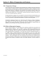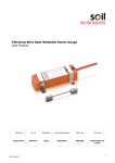
1
Heavy Duty Vibrating Wire Piezometer User Manual Man033 4.0.2 17/04/2013 Chris Rasmussen Phillip Day Chris Rasmussen Manual No. Revision Date Originator Checked Authorised for Issue User Manual 1 Contents Section 1 : Foreword ....................................................................................................................................... 3 Section 2 : Introduction ................................................................................................................................. 4 Section 3 : Effect of Temperature and Pressure .................................................................................. 5 3.01 3.02 Section 4 : 4.01 4.02 4.03 4.04 Section 5 : 5.01 5.02 5.03 5.04 5.05 5.06 5.07 Temperature Change .................................................................................................................... 5 Effect of Barometric Pressure...................................................................................................... 5 Preparation and Installation of Piezometer .................................................................... 6 Removal and Assembly of Filter Elements ............................................................................... 6 Pre-Installation Base Reading ..................................................................................................... 6 Borehole Installation ..................................................................................................................... 6 Installation in Fill ........................................................................................................................... 7 Installation and Termination of Cable ............................................................................... 8 Installation in Trenches ................................................................................................................ 8 Cable Jointing ................................................................................................................................. 8 Preparation of the cable ............................................................................................................... 9 Conductor connectors ................................................................................................................... 9 Fitting Mould ................................................................................................................................... 9 Filling with resin ............................................................................................................................ 9 Termination of cables ................................................................................................................... 9 Section 6 : Calibration Details ................................................................................................................... 10 Section 7 : Use of Temperature Correction Coefficients ................................................................. 12 Section 8 : Troubleshooting ....................................................................................................................... 13 TROUBLE SHOOTING FLOWCHART ............................................................................................................. 14 Appendix A. Sample Calibration Certificate.......................................................................................... 15 Appendix B. EEC Declaration Of Conformity ........................................................................................ 16 Appendix C. Conversion Factor Chart ..................................................................................................... 17 User Manual 2 Section 1 : Foreword It is essential that the equipment covered by this manual is both installed and operated by competent and suitably qualified personnel. They must both READ AND UNDERSTAND the procedures outlined in this manual before attempting installation or operation of the equipment on site. WARNING: it is vital that the person(s) installing these piezometers is(are) familiar with the taking of pre-installation base readings. All systems are designed to operate consistently under normal field conditions, and although their components are relatively robust, they will not survive mishandling or neglect. Treat all items with respect and handle with care. These techniques serve as a general guide and will require modification to suit particular circumstances on site. User Manual 3 Section 2 : Introduction The piezometer tip comprises a porous element assembled to a vibrating wire transducer. The transducer body is constructed throughout from high integrity materials. The sensing wire, diaphragm and anchor comprise an independent unit. An electrical surge protector is included in the design to prevent coil damage should excessive voltages be induced into the connecting cable during electrical storms. The piezometer body is earthed to the connecting cable's screen. The transducer consists of a rigid cylinder, sealed at one end by a firm bulkhead and at the other by a thin diaphragm which serves as an elastic, force sensing member. A thin steel wire strung between these two points is tensioned and firmly anchored during manufacture. Set at the mid-position on the wire a coil/magnet assembly provides the means of exciting the wire into oscillation, the frequency of which is dependent on wire tension. Pore water pressure acting on the diaphragm causes it to deflect thus changing the wire's tension and resonant frequency. The readout unit supplies an electrical pulse to the coil/magnet assembly which in effect plucks the wire and causes it to vibrate at its resonant frequency. The coil/magnet assembly then acts as a pickup as the oscillations of the wire through the magnetic field induce an alternating current in the coil which is detected by the readout. The readout converts the sinusoidal alternating voltage to a square waveform which may easily be timed using a frequency oscillator. In this way the period of oscillation may accurately be measured. The relationship between a change in the period of oscillation and the strain of the wire is non-linear. Basic readout units simply give a reading in period units, which must be manually converted, to the appropriate units by use of formulae. More sophisticated readout units, such as the Soil Instruments' Portable Vibrating Wire Logger, are programmable to give a direct reading in the appropriate engineering units and also to store a series of readings in nonvolatile memory chips for future transfer to computer software. User Manual 4 Section 3 : Effect of Temperature and Pressure 3.01 Temperature Change The materials used in the construction of the transducer are carefully chosen and controlled in order to reduce the effect of ambient temperature changes on readings. In addition the strain wire assembly is evacuated when it is sealed during manufacture, which considerably reduces internal air pressure on the diaphragm when the piezometer is heated (this might give rise to false negative readings in extremes). The significance of temperature change is always with respect to the temperature difference between the current time and the time of the preinstallation base reading. As a `rule of thumb', installed temperature changes of less than 10 o C are not, for practical purposes, significant. If large temperature changes are to be expected in the ground where the piezometers are to be installed then consideration must be given to specifying the incorporation of a thermistor coil in each transducer or the separate installation of another temperature measuring device in order to provide the temperature data required if corrections are to be applied. Temperature gradients across the unit, triggered by rapid changes in ambient temperature, will produce considerable reading error. For this reason it is essential that pre-installation base readings are only taken after sufficient time has been allowed for the transducer to stabilise at the ambient temperature. Piezometers must be immersed in shallow water and shaded from direct sunlight until readings have been seen to settle. 3.02 Effect of Barometric Pressure External pressure applied to the diaphragm of the transducer modifies the wire tension and thus its resonant frequency. Such a change is used to determine the magnitude of the applied pressure. However, since the unit is evacuated and sealed during manufacture subsequent external variations in barometric pressure will cause a differential force to act across the diaphragm which will affect the tensioned wire proportionally. Again the effect is most significant with thin diaphragms i.e. low range units. Thus for a 50mH 20 transducer a ± 10 millibar change in ambient barometric pressure (equivalent to 100 mm of water head) relative to the encased pressure within the unit, will modify the reading by the equivalent of ± 100 mm of water head, even though the external water head to be measured remains constant. Thus in applications where such relatively small variations are considered to be significant, correction of reading errors due to barometric pressure changes should be applied on a pro rata basis (for this purpose a note of barometric pressure on the day of the preinstallation base reading is required and also an accurate barometer must be available on site). User Manual 5 Section 4 : Preparation and Installation of Piezometer 4.01 Removal and Assembly of Filter Elements The ceramic filter must be soaked in clean water for at least 24 hours prior to installation. Unscrew the nose from the support stem and remove the ceramic filter and sealing washers. Immerse the ceramic filter upright in clean water. Shortly before installation refit the ceramic filter. This operation is carried out with the piezometer immersed in water to ensure that it is air free First unscrew the support stem and invert the piezometer body, shaking it if necessary, until all the air has been expelled. Screw the support stem into the body. With sealing washers correctly positioned replace the ceramic filter and screw on the nose. For stainless steel elements remove the securing set head screw completely (ensure it is placed in a safe place) and with the piezometer placed in clean water remove the filter assembly. Invert the piezometer and the filter so on air remains in either, reassemble the filter and refit the set screw. Ensure the piezometer is fully immersed throughout this operation and stays so until immediately prior to installation 4.02 Pre-Installation Base Reading It is necessary to establish a base reading for each instrument prior to installation. Prior to proceeding with the procedure below, the operator should be familiar with the use of the Vibrating Wire Readout/Logger. Operation instructions for the Vibrating Wire Readout/Logger can be found in User Manual No. 45. Ensure that the piezometer is totally immersed in water to the depth of a few centimetres only and is shielded from direct sunlight. Connect the instrument cable to Vibrating Wire Readout/Logger and record reading in frequency or period units. Wait 15 minutes and repeat reading operation. A value identical to that obtained in above indicates that the transducer has stabilised to the water temperature. Record reading with the prevailing barometric pressure and water temperature. Should results obtained be at variance, continue reading until stability is noted. Record with the prevailing barometric pressure and water temperature. 4.03 Borehole Installation The borehole diameter 75 - 150mm, is usually driven in soils using shell and auger and in rock using rotary water flush drilling. Air flush and consequent entrapment of air in the ground should be avoided. The sides of the borehole in the vicinity of the piezometer tip should be free from mud cake and debris. If the hole requires casing, this is withdrawn to keep pace with the installing operation. On completion of the borehole consideration should be given to flushing it with fresh water especially if fine silt is likely to invade. A head of water will ease installation of the piezometer User Manual 6 but obviously this is not appropriate in highly impermeable soils. If the borehole is completely dry add a little water to cover the instrument during installation. Place coarse clean filter sand through the water (a tremie pipe is useful for this) and compact to the proposed base of the piezometer tip. Allow time for the sand to settle, particularly if the water level is high. Mark the proposed depth of the tip on the piezometer cable using coloured P.V.C. adhesive tape. Remember to take account of any borehole casing remaining above ground level. Just prior to installation measure the water level in the borehole. Very carefully lower the piezometer down the borehole until the tape mark coincides with the top of the casing. Take a reading on the piezometer, allowing time for temperature equilibrium to be established. Compare the calculated head of water with the measured water level. This is a very useful operational test. Place further filter sand until the tip is covered by at least 150mm. When using a punner to compact the filter material take great care not to foul or damage the cable. Remember to allow time for the sand to settle as it is difficult to remove surplus sand without causing considerable disturbance. A plug to prevent entry of grout into the filter is usually placed in the form of bentonite pellets. Alternatively balls of stiff bentonite, normally not larger than 50mm diameter, are dropped through the water and tamped into place. Backfilling is completed to ground level with an impervious grout, generally a bentonitecement mix placed through a tremie pipe positioned above the bentonite plug and withdrawn as grouting proceeds. If more than one instrument is being installed it is vitally important to clearly identify the cables using colour coded P.V.C. adhesive tapes. 4.04 Installation in Fill This is essentially similar to installation in shallow soil foundations. In clay fill the piezometer may either be placed in a sand pocket or in direct contact with the fill material. This latter operation is performed using a mandrel to form an impression into which the piezometer is placed. In rock fill the tip should be surrounded by clean coarse filter sand. User Manual 7 Section 5 : Installation and Termination of Cable Connecting cable is laid in a trench deep enough to provide protection from mechanical damage. In certain situations the cables may be run in protective conduits or cast into concrete. However, great care should be taken to protect cables at interfaces between such relatively rigid conduits and flexible soil areas should this method be favoured. The choice of suitable protection material surrounding the cable along the trench length will depend on local factors, but in all cases should be fine grained with a particle size less than 0.5mm and not contain any sharp particles. Fine sand is favoured in free draining areas, but should be replaced by screened silt or clay based soil where lower permeability’s are required. Failure to do so could result in piping along the trench lines. 5.01 Installation in Trenches The cable, which must be screened, should be laid in a trench deep enough to provide protection from mechanical damage. Alternatively in certain situations the cables may be run in protective conduits or cast into concrete, however, great care should be taken to protect cables at interfaces between such relatively rigid conduits and flexible soil areas should this method be favoured. When cables are to be laid in a trench they should be protected for 150mm above and below by compacting in stone-free material normally sand, silt or clay. Although sand is often most convenient to use only silty clay or clay should be used where the creation of a drainage path would be undesirable. Where the trench passes through the impervious clay core of an embankment dam additional cut-offs across the trench may be necessary. If the trench is to be backfilled using rockfill or coarse granular material the thickness of the protective layer over the cables should be increased to 250mm. The trench cable must be connected to the borehole cable by use of a proper electrical jointing kit as detailed in appendix 1. It is desirable to avoid any other cable joints but where this is not possible the same kits must be employed. The effectiveness of these joints largely depends on the care with which the jointing operation is carried out. The cables should be laid loosely in the trench, snaked to prevent strain due to ground movements; in most cases a wavelength of 3m and an amplitude of 200mm should be sufficient. In certain cases it may be advisable to separate the cables from each other in the base of the trench. The cables should be looped on crossing an interface where differential ground movements might be anticipated. The cables may also be looped at cable joints. The cables should be identified using coloured P.V.C. tape applied at regular intervals. The correct functioning of the instrument should be checked before backfilling the trench. Compaction of backfill should be carried out using only hand operated equipment. It may be advisable to clearly mark out or survey the position of the instrument trench, particularly if there is to be further excavation or borehole drilling in the vicinity. A record of the trench position and depth should be kept and it should be pegged out. 5.02 Cable Jointing It is desirable to minimise cable joints, but where they are unavoidable, a special joint kit may be supplied. The effectiveness of this joint largely depends on the care with which the jointing operation is carried out. Refer to figures 2 and 3. User Manual 8 5.03 Preparation of the cable Thoroughly scrape all wax and dirt from each cable end for approx. 150mm. Prepare the cable ends as shown. Stagger the individual connections. 5.04 Conductor connectors Use the crimped connectors to join the conductors. Ensure electrical continuity of outer armoured screen is re-established across the joint and that the piezometer is reading as expected. Use the electrical insulation tape to wrap the connectors and apply one layer half lapped over connector area only. 5.05 Fitting Mould Trim the ends of the mould with a sharp knife to suit the diameter of the cable. Hold the mould halves in place centred over the splice. Snap both halves together and fit the pouring spouts in the holes. Ensure that both seams are completely snapped together. Tape the ends of the mould body to form a seal. 5.06 Filling with resin Mix the resin thoroughly and maintaining the mould in a level position, spouts uppermost, pour the resin through one spout until both spouts are completely filled. When the resin has solidified and cooled remove the spouts. NOTE: In cold weather (below 15° C) the resin becomes very viscous. It is therefore advisable to keep the resin in a warm place prior to mixing. Mix the compound until its temperature starts to rise, this decreases the viscosity. 5.07 Termination of cables The cables are normally terminated in multi-channel terminal units. The cables enter through waterproof glands. The terminal units have a hinged cover secured by two screws. Unscrew and open the hinged cover. Unscrew the four fixing screws holding the terminal panel and carefully remove it without straining the connecting leads. Prepare the cables by stripping and cutting back 20 mm approx. of the outer insulation and screen. Remove the rubber packing and strip back 5 mm of the conductor insulation. Slacken the entry glands and insert the cables. Make connections to the contact blocks. The earth leads/screen from piezometers are not normally connected at the terminal units but leave sufficient lengths available to allow this to be done retrospectively should site conditions require it. Re-tighten the glands to grip the cables. Replace the terminal panel and secure. Connect the readout unit to each instrument in turn to check connections. User Manual 9 Section 6 : Calibration Details Unless it is only required to save piezometer readings in period units, it is necessary to enter calibration data within the Vibrating Wire Transducer Table. For further details of the Vibrating Wire Logger or Vibrating Wire Temperature Logger, refer to User manual nos. 45 and 96 respectively. A example of a calibration certificate can be found overleaf with a selection of Gauge Constants enabling the operator to read and log data directly in the engineering units desired. The mathematical relationship between the frequency of vibration of a tensioned wire and the force applying the tension is an approximate straight line relationship between the square of the measured frequency and the applied force. Engineering units of measurement maybe derived from the frequency-based units measured by vibrating wire readouts, in 3 traditional ways:From ‘Period’ units and from ‘Linear’(f^2/1000) units using two methods: a simple Linear equation or a Polynomial equation. Calculation using ‘Period’ units The following formula is used for readings in ‘Period’ units. E = K (10^7/P0^2 – 10^7/P1^2) Where; E is the Pressure in resultant Engineering units, K is the Period Gauge Factor for units of calibration (from the calibration sheet), P0 is the Period ‘base’ or ‘zero’ reading P1 is the current Period reading. This method of calculation is used by the Soil Instruments Vibrating Wire loggers’ (models RO-1-VW-1 or 2 and with serial numbers starting VL or TVL) internal processors’, for calculating and displaying directly on the loggers’ LCD screen, the required Engineering based units. The loggers’ require ‘Period’ base or zero reading units for entering into their channel tables, to calculate and display correctly the required engineering units. If an Engineering-based unit is required other than the units of calibration, then the correct K factor will have to be calculated using the standard relationship between Engineering units. For example, if the units of calculation required were in mH2O and the calibration units were kPa, we can find out that 1kPa is equal to 0.1022mH2O, so we would derive the K factor for mH2O by multiplying the K factor for kPa by 0.1022. Please see conversion factors in Section 10. Calculation using Linear units The following formula is used for readings in ‘Linear’ units. E = G (R0 – R1) Where; User Manual 10 E is the resultant Engineering unit, G the linear Gauge factor for the units of calibration (from the calibration sheet), R0 is the Linear ‘base’ or ‘zero’ reading R1 is the current Linear reading. Again the Linear gauge factor for units other than the units of calibration would need to be calculated using the same principles as stated in the last paragraph of the ‘Period unit’ section. Linear unit calculation using a Polynomial equation Linear units maybe applied to the following polynomial equation, for calculation of Engineering units to a higher order of accuracy. E = AR1^2 + BR1 + C Where; E is the resultant Engineering unit, A, B and C the Polynomial Gauge factors A, B and C, from the instrument’s calibration sheet, R1 is the current Linear reading. The value C is an offset value and relates to the atmospheric pressure experienced by the piezometer at the time of calibration. This figure will have changed at the time of installation due to changes in altitude or barometric pressure, so C should be re-calculated at the installation time as follows: C = - (AR0^2 + BR0) Where; A and B are as above, R0 is the Linear ‘base’ or ‘zero’ reading. Please note that the sign of the re-calculated value of C, should be the same as the original value of C, so if the original is negative then the recalculated value should also be negative. Conversion to engineering units other than the units of calibration, would best be done after conversion, using a factor calculated using the same principles as stated in the last paragraph of the ‘Period unit’ section. Please see conversion factors in Section 10. User Manual 11 Section 7 : Use of Temperature Correction Coefficients Soil Instruments vibrating wire transducers have been carefully developed over many years, so that the combination of material types in the instruments’ build, its design and the manufacturing processes, results in instruments which are little affected by changes in temperature. Any changes are regarded as insignificant. Therefore, as standard, Soil Instruments’s vibrating wire instruments are not provided with temperature correction coefficients, even though they may be specified with a thermistor. It should be noted that while an instrument is changing temperature, the stresses created across the transducer body by temperature gradients, will induce changes in the instruments reading, but once the instrument has stabilised at its new temperature, these differences will disappear. The time for an instrument to fully stabilise at a new temperature will be in the order of 30 to 40 minutes. At the time of ordering, instruments may be specified, calibrated with individual temperature correction coefficients. If supplied with this coefficient, then the coefficient may be applied using the following formulae and example: ET = E + TK (T1-T0) Where; ET is the temperature corrected Engineering reading, TK the temperature coefficient, T1 the current instrument temperature and T0 the base or zero reading temperature (both in degrees C and recorded from the instruments internal thermistor). The temperature coefficient, TK, will be in units of Engineering per degree c, as per the calibration certificate. Ensure that the temperature coefficient is converted to the same units of Engineering as per the calculated E, via a conversion factor before applying the temperature correction. User Manual 12 Section 8 : Troubleshooting If a failure of any vibrating wire transducer or the electrical cable is suspected, the following steps can be followed. The transducers themselves are sealed and cannot be opened for inspection. The “Troubleshooting Flowchart” should also be followed if any instrument failures are suspected. The steps below and the Troubleshooting Flowchart are applicable generally to any vibrating wire instrument. STEP 1 Before any of the following steps are followed, the portable data logger should be used to verify the stability of the reading and the audio signal from the portable logger should be heard. An unstable (wildly fluctuating) reading from a transducer, or an unsteady audio signal are both indications of possible problems with instruments or their related electrical cables. If a portable data logger is giving faulty readings or audio signals from all transducers, a faulty readout unit must be suspected. Another readout unit should be used to check the readings from the transducers and Soil Instruments. should be consulted about the faulty readout unit. STEP 2 The resistance across the two conductors of the electrical cable should be checked. This can be done using a multimeter device across the two exposed conductors if the cable has not been connected to a terminal cabinet, or can be done just as easily across the two conductors if the instrument has been connected to such a terminal (or datalogger). The resistance across the two conductors should be approximately of the order of 120 to 180. The majority of this resistance will come from the transducer (say approximately 130). Before proceeding to Steps 3 and 4, the continuity should be checked between conductors and earthing screen of the electrical cable. If a continuity exists, a damaged cable is confirmed. STEP 3 If the resistance across the two conductors is much higher than the values quoted in “STEP 1” (or is infinite), a severed cable must be suspected. STEP 4 If the resistance across the two conductors is much lower than the values quoted in “STEP 1” (say 80 or less) it is likely that cable damage has occurred causing a short in the circuit. STEP 5 If the resistance is within the values quoted in “STEP 1” (i.e. 120 to 180), AND no continuity exists between conductor and earth screen and on checking the reading from the transducer, it proves to be still unstable or wildly fluctuating, it must be assumed that the integrity of the circuit is good. A faulty transducer could be suspected if neighbouring construction activities do not account for the anomaly, Soil Instruments should be consulted. If the point at which the cable is damaged is found, the cable can then be spliced in accordance with recommended procedures. User Manual 13 TROUBLE SHOOTING FLOWCHART R less than 80 User Manual 14 Appendix A. Sample Calibration Certificate User Manual 15 Appendix B. EEC Declaration Of Conformity User Manual 16 Appendix C. Conversion Factor Chart Pressure, Stress & Modulus of Elasticity MN/m2 or MPa kN/m2 or kp or kPa kgf/cm2 bar atm m H2O ft H2O mm Hg tonf/ft2 psi or lbf/in2 lbf/ft2 1 1000 10.197 10.000 9.869 102.2 335.2 7500.6 9.320 145.04 20886 0.001 1 1.019 x 10⁻² 0.0100 9.87 x 10⁻³ 0.1022 0.3352 7.5006 0.0093 0.14504 20.886 98.07 1 0.9807 0.9678 10.017 32.866 735.56 0.9139 14.223 2048.1 100.0 1.0197 1 0.9869 10.215 33.515 750.06 0.9320 14.504 2088.6 101.33 1.0332 1.0132 1 10.351 33.959 760.02 0.9444 14.696 2116.2 9.7885 9.983 x 10⁻² 9.789 x 10⁻² 9.661 x 10 1.4198 204.45 2.983 x 10⁻³ 2.9835 3.043 x 10⁻² 2.984 x 10⁻² 2.945 x 10⁻² 0.3048 1.333 x 10⁻⁴ 0.1333 1.3595 x 10⁻³ 1.333 x 10⁻³ 1.315 x 10⁻³ 1.362 x 10⁻² 4.469 x 10⁻² 1 1.243 x 10⁻³ 1.934 x 10⁻² 2.7846 0.1073 107.3 1.0942 1.0730 1.0589 10.960 35.960 1 6.895 7.031 x 10⁻² 6.895 x 10⁻² 6.805 x 10 4.788 x 10⁻² 4.883 x 10⁻⁴ 4.788 x 10⁻⁴ 4.725 x 10⁻⁴ 9.807 x 10 -2 0.100 0.1013 9.788 x 10 6.895 x 10 -3 -3 4.788 x 10⁻⁵ User Manual -2 -2 1 -2 3.2808 73.424 9.124 x 10 1 22.377 2.781 x 10⁻² 0.43275 804.78 0.7043 2.3108 4.891 x 10⁻³ 1.605 x 10⁻² 0.3591 51.714 6.426 x 10 -2 62.316 15.562 2240.0 1 144.00 4.464 x 10⁻⁴ 6.944 x 10⁻³ 1 17 Figure 1: Vibrating Wire Piezometer Assembly User Manual 18 5.00 Scrape Sheath 5.00 Cut Sheath Back Cut Sheath Back A 25.00 Scrape Sheath A 25.00 Figure 2: Preparation of Cable Joint User Manual 19 Pouring Spouts Mould Bodies IMPORTANT : Cables and Connector Must be Centerd in Mould. Figure 3: Cable Joining kit Wrapping Electrical Connectors and Mould Fitting Bell Lane, Uckfield, East Sussex t: +44 (0) 1825 765044 e: [email protected] TN22 1QL United Kingdom f: +44 (0) 1825 744398 w: www.itmsoil.com Soil Instruments Ltd. Registered in England. Number: 07960087. Registered Office: 5th Floor, 24 Old Bond Street, London, W1S 4AW User Manual 20