1
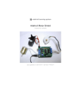
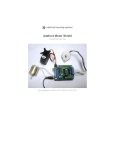
Phase IV ILC Dover Michelle DeBonis Kirk Harbaugh Bryan Hennigan Melynda Schreiber PROOF OF PROTOTYPE Table of Contents I. Project Scope: ....................................................................................................................................... 3 I. Present State: .................................................................................................................................... 3 II. Problem Definition: ........................................................................................................................... 3 II. Performance Validation Requirements: ............................................................................................... 4 I. Needs: ............................................................................................................................................... 4 II. Wants: ............................................................................................................................................... 4 III. Constraints: ................................................................................................................................... 4 IV. Metrics: ......................................................................................................................................... 5 V. Relationship mapping: ...................................................................................................................... 5 III. Prototype Development: .................................................................................................................. 6 I. Project Design Path ........................................................................................................................... 6 II. Prototype .......................................................................................................................................... 7 III. Actuation ........................................................................................................................................... 8 IV. Height Control ................................................................................................................................... 9 V. Angle Control ..................................................................................................................................... 9 VI. Trowel Attachment .......................................................................... Error! Bookmark not defined.0 VII. Velocity Control............................................................................... Error! Bookmark not defined.1 VII. Template Holding ............................................................................ Error! Bookmark not defined.1 IV. Prototype Testing ............................................................................. Error! Bookmark not defined.3 V. Risk Mitigation ................................................................................... Error! Bookmark not defined. VI. Safety .......................................................................................................................................... 17 VII. Budget ......................................................................................................................................... 18 Appendix A: Fabrication Package ........................................................... Error! Bookmark not defined. Appendix B: Users Manual .................................................................................................................. 20 Appendix C: Calibration Plan............................................................................................................... 23 Appendix D: Bill of Materials .............................................................................................................. 26 Appendix E: Time Log .......................................................................................................................... 27 2 Introduction to Performance Validation: Phase IV represents a validation of the developed prototype as a viable solution for ILC Dover. The problem definition and design requirements have been refined and updated. This reiterated design structure provides the framework for the validation process, ensuring that the prototype remains aligned with ILC’s needs and wants. Through a series of strategic tests and analysis of results, the achievement of target metrics will be determined. A final road map has been created to guide ILC from the conclusion of the Senior Design Process to project completion, including further testing, operation, and safety manuals. Project Scope: Present State: Space suit gloves are manufactured by ILC Dover for their customers at NASA. Silicone pads for the space suit gloves are made individually by troweling technicians using pre-existing plastic templates. First, a template is placed over a board. A room temperature vulcanizing (RTV) silicone rubber material is applied in front of each pad template. The RTV silicone is troweled over the template area manually. The inability to control pad thickness through the present process results in failure of the Thermal Micrometeoroid Garment (TMG) layer of the glove. Quality control testing of each pad’s thickness is required to guard against such failure. At a production rate of 96 pairs annually with 26 pads per pair, extra testing is very time consuming and expensive. Developing a more reproducible troweling process will save time and money. Problem Definition: Design an automated, reproducible, controlled troweling process for the manufacture of silicone padding components of the Thermal Micrometeoroid Garment (TMG) section of a space suit glove for the project sponsor, ILC Dover. Enhance process • Improve quality and reliability • Reduce operator dependance • Improve reproducibility Develop a working prototype • Prototype • Operation manual • Testing manual 3 Verify Prototype • Demonstrate success against chosen target metrics • Present tangible benefits Performance Validation Requirements: Through communication with ILC Dover, a comprehensive outline of the solution requirements and limitations has been developed. These design requirements provide the benchmarks for success of the solution. The following summary is intended to illustrate those problem specifics. Needs: A ranked list of the necessary requirements for a successful prototype Table 1: Customer Needs Rank Needs Descriptions 1 Reproducible Results Process needs to deliver consistent pad quality through variable settings 2 Steady Actuation 3 Control Pad Thickness Trowel stroke needs to have constant velocity and free of disturbances and vibrations Adjustable settings need to be able to deliver different thicknesses The process must be automated 4 Automated 5 Easy Cleaning of Trowel 6 Maintain Ridge Profile Process must allow for simple cleaning of the trowel after each run The process must employ the same ridge profile of the present trowel Wants: A ranked list of desired attributes to achieve customer needs Table 2: Customer Wants Rank Wants Descriptions 1 Cut Production Time Streamline the pad troweling process to increase efficiency 2 Use Preexisting Trowel ILC wants the same trowel profile utilized 3 Accessible Trowel ILC wants trowel to be easily reached for cleaning 4 Speed Control ILC wants variable speed settings 5 Height Control ILC wants variable height settings 6 Angle Control ILC wants variable angle settings 7 Simplicity of Assembly 8 Simplicity of Operation ILC wants the prototype to be as simple as possible, limiting special processes ILC wants operation of the prototype to be uncomplicated Constraints: A list of project constraints that must be met Table 3: Project Constraints Constraints Notes Resistant to Toluene and MEK Chemicals used for cleaning Compatible with Templates The existing templates must be used Prototype needs to be tabletop sized No computer controls Prototype Size Controls independent of computers 4 Metrics: A tabulated summary of performance metrics with current and target values Table 4: Performance Metrics Rank Metric Current State Target 1 2 3 4 5 6 7 8 Pad Thickness Range Height Range Speed Range Cost Angle Range Number of custom parts required Prototype Volume Prototype Weight 0.06-0.14” No Control No Control N/A 90 ° (fixed) N/A N/A N/A .027-.035” 0-.5” 0.25-12 in/s $5,000 ±45 ° ≤ 15 ≤ 3 ft3 ≤ 40 lbs Relationship mapping: A hierarchical mapping, illustrating the relationships between project goals, customer needs/wants, project constraints and performance metrics. Fig.1: Project Hierarchical Attribute Mapping 5 Prototype Development: Using the solution requirements and performance metrics, the team was able to develop an appropriate design path for the project (Fig. 2). That design path, feedback from ILC, along with referring to the developed validation criteria led to a series of design iterations and eventually a final prototype. This prototype captured all the necessary requirements. Further testing would validate the prototype after meeting the target metrics. Project Design Path Figure 2 presents the possible options for each identified decision level, moving from the highest overreaching level of general project path down to specific control subsystems. Each decision was discussed and after weighing the pros and cons, with careful consideration of our sponsor-defined project scope and deliverables, a decision was made and the next decision was approached. At the time of the project, no “market-ready product was available and ILC decided to abandon their existing prototype. Pursuing a new concept was ideal in order to maximize the time available to fine-tune the prototype. A new concept would allow complete control in accommodating ILC’s design requirements Actuating the board rather than the trowel was decided in order to maximize simplicity and ensure steady actuation. This method effectively holds the angle/height controls stationary in order to increase reproducibility. Pneumatic actuation was selected in the interest of simplicity, low price and minimal weight. For both height and angle control, a unique subsystem was pursued in order to maximize simplicity and to ensure reproducibility and integration into the entire system Fig. 2: Proposed Project Decision Path 6 Prototype Moving along the derived project design path, the group was able to iterate to the final prototype. Figure 3, below, presents the prototype with callouts to provide detail as well as appropriate parts labeled with common vocabulary used for clarity. Trowel Shaft Shaft Collar Toggle Clamps Angle Control Knob Trowel Board Figure 3: Prototype Detail 7 Cam Levers Prototype Design Aspects 1) Actuation • Pnuematic Bimba cylinder actuates the Trowel Board • Linear guide rails at the edges of the Trowel Board provide support • All components directly mounted to the Base Plate. 2) Height Control • The Shaft Assembly bridges the two Support Towers • The assembly is set to the proper height using Plastic Shims underneath the Trowel • 4 adjustable Cam Levers lock the assembly at the proper height. 3) Angle Control • The Trowel is attached to the Shaft, which can freely rotate ±45° • An Angle Indicator connected to the Shaft is held at the appropriate angle by tightening the Angle Control Knob 4) Trowel Attachment • The Trowel is connected to the Shaft Collars by a dowel pin which allows it to rotate 180° freely • The Trowel is locked in the down position for troweling by Spring Loaded Pins • For cleaning, the Trowel swivels upward to rest on a flat in the Shaft 5) Velocity Control • The control method uses adjustable Needle Valves which control the flowrates into and out of the cylinder • Adjustable Cushions in the cylinder provide a safe effective decelleration 6) Template Holding • The Trowel Board uses Toggle Clamps to secure the template during actuation. 1. Actuation Below the actuation (Fig 5) aspect of the prototype and its components (Fig 4) is detailed and tied back to performance validation. Bimba Cylinder Needle Valves For Speed Control Rated for 1.44 Million Cycles 30-110 operating PSI 15-30 breakaway PSI 20-80 C operating temperature Guide Rails To ensure steady actuation & reproducibility Rubber Feet For Leveling Base Plate Figure 4: Actuation Components 8 Figure 5: Actuation Method The automatic actuation of the trowel board past the stationary trowel is generated by engaging airflow into the Bimba cylinder, by activating a 2-way control lever in the appropriate direction. The design favors simplicity of operation as desired. The guide rails ensure a smooth motion and stability across the board as the trowel engages the RTV. 2. Height Control The method and components of the height control are highlighted in Figure 6 below. As stated before the shaft assembly is set at the appropriate height using plastic shims placed between the bottom of the trowel and the top surface of the trowel board. The easy-to-use cam levers lock the trowel at the appropriate height to ensure reproducibility and provide control of pad thickness. Cam Levers Height Setting Cam Levers Figure 6: Height Control 3. Angle Control Figure 7 outlines the angle control mechanism. The shaft sits snuggly in precision-reamed plastic adapters at either end, which allows for easy rotation. At the front end an angle indicator shows how much the trowel is angled, and the control knob is tightened to hold the angle tight. 9 Angle Control Knob Angle Indicator Figure 7: Angle Control 4. Trowel Attachment In order to allow for easy cleaning of the trowel while retaining the rigidity required for controlling the pad thickness and maintaining the ridge profile, the trowel was designed to be able to swivel between a troweling position (down) and cleaning position (up). (Figure 8) The trowel assembly is locked in place by L-shaped spring loaded pins which mate to holes in the shaft collars. Clean Position Shaft Collar Hole Trowel Position Spring-Loaded Pins Figure 8: Trowel Attachment 10 5. Velocity Control The velocity of the cylinder (and the trowel board) is controlled by adjusting how much air enters and exits the cylinder on either side of the slide. This is controlled by opening or closing the needle valves which could the air inlet and outlet hoses to the cylinder. By opening the valves and allowing more air to flow in/out the speed will increase. A separate double-acting lever valve allows air to pass between the needle valves and the in-house air supply. The concept is displayed in Figure 9 below. DoubleActing Lever Pressure Regulator Bimba Slide Figure 9: Velocity Control 6. Template Holding The template must be securing held so the troweled pads remain consistent. The design (Fig. 10) uses four easy-to-operate toggle clamps to firmly hold the template it place while the machine actuates. The design is easy to use and contributes to reproducibility and simplicity of operation. Care must be taken when releasing the clamps post-troweling; the rubber ends can sometimes stick to the template and pull it, thereby disrupting the troweled pads. Perhaps a lubricant can be applied to limit this issue. 11 Toggle Clamp Template Position Figure 10: Template Holding Those 6 detail areas demonstrate the key features of the prototype design in line with the validation deliverables. The finished prototype is operational and testing is needed to verify its success, which will be discussed in the next section. The only discrepancy between the delivered prototype and an ultimate solution is complete performance validation and proper calibration to ideal settings. A guide for completing those final tasks will be presented. The performance validation of the design is presented in table 5 below. Table 5: Prototype Values 12 A complete design package has been provided for ILC in Appendix A. This includes machinist drawings for each of the 13 custom-machined parts as well as sub-assembly and assembly drawings. There is also a fabrication plan, along with appropriate suggestions/lessons learned for a future iteration. A full operator’s manual has been included in Appendix B which details the procedures required for effectively operating the machine. Prototype Testing The prototype developed in the first three phases of the senior design project process must be tested and proven to achieve the predefined performance metric goals. Preliminary testing in Phase III demonstrated that the cylinder could produce acceptably linear velocities while troweling RTV. This testing plan will have four major goals: Testing Goals 1. Calibrate the Machine 2. Prove Ability to Control Pad Thickness 3. Prove Steady Actuation 4. Characterize the Machine The bottom three testing goals validate our proof-of-concept prototype derived from the early phases of the design process. The top goal represents the road-map to the completion of the final project solution. Goal 4 has been completed, but ILC will have to re characterize on site and will complete the rest of the validation goals. 1. Calibrate the Machine: 13 The final goal will be to calibrate the prototype to the exact settings which will repeatedly produce the exact desired pad thickness and profile. The methods and strategic plan for ILC to determine the optimal operating settings for the prototype is attached in Appendix C. 2. Prove Ability to Control Pad Thickness To ensure that the prototype delivers an acceptable product, the cured samples will be tested. First the relationship between the prototype height setting and the final pad thickness will be examined. The pad will be measured from bottom to trough using a snap gauge. A correlation between setting and thickness will be determined. The consistency of the samples will be reported. The variation of thickness along the length of the sample will also be examined, measuring at .25” intervals. Future Strategy: Ensure the thickness accuracy of troweled samples a. Report accuracy of +- 0.01” with 95% confidence b. Report level thickness with a deviation of less than +-0.01” with 95% confidence 3. Prove Steady Actuation Once the optimal pressure setting and actuation direction were completed in goal 4, the angle will be locked at 90 degrees and the height will be set at 0.03” using plastic shims. Using (the most irregular template OR the template with the most RTV), each velocity setting at the determined pressure setting will be tested once to examine its linearity. Next the highest and lowest settings will be tested 5 times each. The coefficient of linear regression for each will be determined. Statistical analysis will be conducted to report the confidence interval for linearity. Future Strategy: Adjust height and angle controls to standard settings and prove acceptable velocity linearity (RTV) a. Each setting will be tested once to ensure linear trend b. Upper and lower limits will be tested at least 5 times 4. Characterizing the machine: To determine the best settings all of the 4 possible settings at each of 6 pressure settings between 30-80 PSI, at 10 PSI increments, were examined (No RTV). The velocity of the full trowel-board assembly was measured by evaluating videos of the actuation using lab view. Each trial analysis produced a text file which was processed by a custom Matlab code (uploaded to sakai). The code produced a plot, velocity value, and correlation value. The results are presented in Figure 10 below. If the standard deviation of the trials is more than 0.3 inches/ second, the pressure and setting will be counted as unreliable. Strategy: Determine all viable velocity ranges for all operating settings (No RTV) a. Prove repeatability b. Report best direction of actuation for consistent velocity. c. Report the best pressure setting which allows the optimal velocity range 14 The characterization revealed a potential velocity range of 7-24 inches (Fig 11) per second for using Spencer lab air. Figure 11: Velocity Range At Each Pressure Setting *Note: Noticeably slower velocities were produced on location at ILC. Slower velocities are more beneficial to smoothly troweling RTV. Table 5: Velocity Setting Reliability Pressure 30 PSI 40 PSI 50 PSI 60 PSI 70 PSI 80 PSI Setting 1 0.026485 0.85119 0.64796 0.45199 0.27968 0.30631 Setting 2 0.15342 0.29124 0.53464 1.09 2.3475 0.2434 Setting 3 0.23725 0.16338 0.18164 0.035 0.99671 1.0281 Table 5 above shows the reliability of all the settings. We defined reliability as less than 0.3 standard deviations and highlighted the acceptable settings in green and the unacceptable in red. The trend shows that the lower the setting (slower speed) the more reliable the actuation. ILC’s air supply produced noticeably slower speeds, and correspondingly more reliability. Slower speeds should be pursued first in calibration. 15 Risk Mitigation Failure modes To effectively plan for prototype shortcomings, a summary of possible concern areas with associated contingency plans has been developed. A. The Height Control Subsystem is Insufficient or Inaccurate Risk: The height control subsystem, comprised of locking cam levers moved along vertical slots, could be determined to not meet the needs of the sponsor during phase 4 testing of the prototype. Plan: If this is the case, the issue would be discussed with the advisor and sponsor. Then the system design would be reevaluated using the 80/20 structural beams. The 80/20 beams could be used in conjunction with screws and washers (which slide along the shaft due to the beam cross section) to adjust the height control. B. The Trowel Cleaning Procedure does not work well Risk: The trowel is rotated for cleaning. If the RTV silicone material is too hard to clean from this position, more time to the cleaning process. Plan: If this is the case, after discussion with the sponsor and our advisor, a new plan of action would be developed. In this plan of action, the shaft would be re-machined to allow for the trowel to be directly screwed onto a flat surface to allow for removal without interference. C. The Trowel Attachment System Has Too Much Slop Risk: The trowel attached by spring loaded pins could have too much slop vertically. After height calibration, the plastic shims are removed from beneath the trowel. The trowel could further displace downward if there is too much slop in the system. Plan: If this is the case, after discussion with the sponsor and our advisor, a new plan of action would be initiated. In this plan of action, the shaft would be re-machined to allow for the trowel to be directly screwed onto a flat surface. This alternative design has already been modeled if this risk becomes a problem. Additional lead time for machining and testing would be required. D. The ends of the Bimba Actuator are Unstable Risk: The current design does not support the actuator at the extreme ends. There could be an issue with vibrations or support which would be identified during testing. Plan: If this is the case, after discussion with the sponsor and our advisor, additional aluminum supports at each end of the actuator would be added to the design. Testing and report schedules would be adjusted to reflect additional lead times from machining and assembly. 16 Safety The safety of the proposed concept was considered during the design process. While making the machine, attention must be paid to legal regulations. The Occupational Safety & Health Administration (OSHA) in the United States Department of Labor outlines standards for machines in regulations for standard industry: section 1910 subpart O and P. These sections deal with machinery and machine guarding, and hand and portable powered tools and other hand held equipment respectively. The proposed concept does not legally require any sort of safety guard or machine stop. Operator safety guidelines will be outlined in the final machine manual developed in phase 4 of the project. Some areas to consider include keeping hands clear of moving parts in addition safe operation with pressurized air. Safety Officers from ILC inspected the prototype and determined that it met safety requirements, so long as warning stickers were added along the pinch hazard between the trowel board and towers. Also the control lever must not be mounted so that it takes two hands to operate. Budget Report The project was under budget. Appendix D shows a complete bill of materials with prices and miscellaneous expenses accounting for the total expended budget. Appendix E shows the groups time sheet. Table 6: Budget Report Actual vs. Budget Actual Budget Variance Expenses Actuation Height Control Angle Control Total $1,144.62 - - $ 395.54 - - $23.75 - - $1,563.91 - - 110 - - $1,100.00 - - $0.00 - - $2,663.91 $5,000.00 $2,436.09 Hours Total (Hours) Cost ($10/hour) Actual Cost Totals: 17 Appendix A: Design & Fabrication Package Uploaded to the Executive Level of Sakai 18 Appendix B: RTV Troweling Device User Manual As with any machine, it is imperative to take proper precautions for your own safety. Before operation, allow some time to become familiar with the device. Resting Position Ending Position Connecting/Disconnecting Air 1. The controller has two inputs on one side, and one input on the other side. Insert a ¼” parflex tube by holding down the green “o-ring” on the controller and slipping the tubing in all of the controller inputs. To take out the tubing, hold the “o-ring” down in the direction of the controller and pull the tubing out. 2. Take the two parflex tubes on one side of the controller and insert the free ends into the slide. To insert the tube into the slide hold, the black “o-ring” down and insert the tube. 3. Take the last parflex tube and insert the free end into the house pressure. Height Control 1. To place the trowel in its proper position, unlock the cam levers. 19 2. When these levers are unlocked, and the shaft with the trowel securely attached, the shaft will be able to be moved vertically. Use shims to accurately set the height to a particular position. 3. Place shims beneath to trowel to obtain an accurate height. 4. Lock all the cam levers (4) into place. When the cam levers are in place, they should be in a vertical position. Angle Control 1. To change the angle, use a digital level and lock the level using the knob (as shown above). To assure that the trowel is vertical, the digital level should read out 90 degrees. This does not ensure that the level is perpendicular to the trowel board. 2. To ensure that the trowel is perpendicular, make sure the entire system is level as well as the trowel board itself. Actuation 1. Start with the machine in a resting position. In this position, the toggle clamps should be adjusted where the rubber mount is toward the trowel board. If the toggle clamps are not in the proper position, lower the toggle clamps(4) by pressing the larger lever down until the clamp is locked into position. If the clamps are not in their proper position before the actuation, the clamps could eventually break off due to wear and the actuation would be stopped abruptly. 2. The entire trowel board should be positioned so that it is a couple of inches from the trowel which is at the farthest position on the slide. 3. To operate the machine, move the controller out of the way so that the trowel board will not hit the operator’s hand. Press the controller in the appropriate direction. 20 4. If the template is raised up on the edge, use the controller to slowly move the trowel board under the trowel. Safety Concerns Avoid getting hands and other clothing caught in between the slide and the trowel board. Avoid operating the trowel board with the controller in the way of the board. Avoid operating the trowel board when the toggle clamps are not in their resting position. Care of the System Avoid operating the trowel board when the tubing rises above the board. Running the slide will cause the trowel board to scrape against the tubing which will eventually cause a leak in the tubing. To assure slide longevity, do not get RTV on the slide. Repeated use of strong chemicals may damage the metallic band on the slide. Grease the guide rails every 2 to 3 years to keep them in the optimal condition. Be careful not to get dirt and other grime on the guide rails. Any dirt or grime can cause the rails to slow down and change the speed of the cylinder. If there is significant noise coming from the guide rails, disassemble the guide blocks and clean the system or send it back to the company for cleaning. 21 22 Appendix C: Calibration Procedures In order to calibrate the machine to the optimal settings a strategic series of trial and error testing must be employed. The machine has been characterized (Testing Goal 4) at Spencer lab, but will need to be characterized at ILC using the air supply system on site. Once characterized to ILC’s air, the lowest range should be explored. Using the lowest speed, the trowel would be set to 0.03” off the template and RTV would be troweled. The cured sample would be observed, and if too thick the trowel would be used incrementally higher. If irregularities due to too slow a speed are observed the speed would be increased. Higher speeds should be explored; at least briefly, to observe which end the velocity spectrum produces a smooth profile in the silicon. Through multiple trials the optimal settings would be honed in on and locked. Height Control Procedure: 1. 2. 3. 4. 5. 6. 7. Calipers will be used to verify individual shim height. Shims will be placed to set the height of the trowel. The board and ground will be checked to see if they are level. T-squares will be used to ensure that the trowel is perpendicular to the board. A digital level will be used to ensure that the angle is zero degrees. Check the height of both ends to the trowel and the shaft. Lock all cam levers. Remove shims by releasing the spring loaded pins and flipping up trowel. 8. Set up a camera and record the motion. 9. Plot a graph of height versus time to ensure that there is no unintentional binding created in the manufacturing of the Delrin. Angle Control Procedure: 1. The board and ground will be checked to see if they are level. 2. T-squares will be used to ensure that the trowel is perpendicular to the board. 3. The trowel will be checked to see if the angle displayed on the protractor is actually zero. 4. Tighten the lobe knob. Apply force to the trowel and check if the angle has changed. 5. Untighten the lobe knob to move the trowel to some other appropriate angle. 6. Tighten the lobe knob. Check if the trowel starts to have a change in angle. Speed Control Procedure: 1. Set up the system so that all components are level. 2. Set up the tripod so that it is level and the camera is facing down directly over the top of the plate. 3. Ensure that all Parflex tubing and pipe fittings have been appropriately sealed so that there is no air leakage. 23 4. Turn on air to appropriate pressure. The pressure range must be between 3580 psi. 5. Set the first pressure with one washer inserted between the needle valve and the nut. Turn the needle valve until it cannot be turned anymore. 6. Start the video on the camera. 7. Use the controller to actuate the board with the RTV and template. 8. Stop the video and download the video. 9. Repeat steps for 2, 3, 4, and 5 washers and other pressure settings. Computer Procedure for Speed Control: 1. Open video file in NI Vision Assistance. 2. Set coordinate system and select points with known distances to calibrate the system. 3. Select a region of interest to find edges. 4. Output an excel file. Plot position versus time on a graph to assure constant velocity. 5. Check for zero slope which would indicate stiction. Pad Thickness Consistency Procedure: 1. 2. 3. 4. 5. 6. Repeat Procedure for speed control testing. Remove the template from the board after troweling. Remove the board and allow the pads to cure for 8 hours. Measure the thickness of each trough of each pad with a micrometer. Compare to target thicknesses of .027 to .035 inches. Observe whether the RTV form is acceptable. Note for any bubbles, noticeable discontinuities and uneven RTV profile. 24 Appendix D: Bill of Materials Part Shaft Collars Release Cams L-Spring Pins Toggle Clamps 80-20 Framing 80-20 Framing 3-corner connecter Stock Delrin Stainless Steel Stock Aluminum Bimba Flow Control Center Supports Bimba Cylinder Knob Rail System Number Company Price Amount 9946K24 5720K12 3403A81 4961A66 47065T146 47065T209 47065T244 McMaster McMaster McMaster McMaster McMaster McMaster McMaster $3.53 $11.51 $14.00 $24.56 $25.15 $8.35 $9.86 8739K94 8513T31 8741K39 88915K753 8975K411 8975K114 FQPS2K McMaster McMaster McMaster McMaster McMaster McMaster Bimba Bimba Bimba UBCS-18 UB-18221XCM JCL-116 Shipping 4 4 2 4 1 1 8 Total Price $14.12 $46.04 $28.00 $98.24 $25.15 $8.35 $78.88 $31.95 $85.26 $6.50 $81.39 $16.81 $51.79 $15.05 1 2 1 1 2 1 1 $31.95 $170.52 $6.50 $81.39 $33.62 $51.79 $15.05 ? $20.60 $294.00 2 1 $41.20 $294.00 ? $ 13.84 $ 8.39 $ 50.00 $ 50.00 $ 122.23 $1.24 1 $1.24 R165181420 Reid Select Rexroth $99.53 2 $199.06 R160580431 Rexroth $158.39 2 $316.78 $1,541.88 25 - Appendix E: Time Log Time Report Name Bryan Date 11/15/2010 Time In 8:30 Time Out 12:00 Total Time 3.5 Task Cut & Assembled 80-20 Bryan 11/15/2010 2:30 5:00 2.5 Cut Stock Bryan 11/17/2010 8:30 12:00 3.5 Cut Stock/Assembly Bryan 11/17/2010 3:30 5:00 1.5 Shaft Collars Bryan 11/22/2010 8:00 12:00 4 Bryan 11/30/2010 1:00 3:30 2.5 Testing Goal 1 Bryan 12/1/2010 10:00 12:00 2 Testing Goal 1 Bryan 11/22/2010 2:30 4:00 1.5 assembly Bryan 11/23/2010 8:30 12:00 3.5 Bryan 11/23/2010 1:00 2:00 1 Protractor, trowel blocks, assembly Protractor Bryan 11/29/2010 8:30 11:00 2.5 Final Assembly Kirk 11/15/2010 8:00 5:00 8 Plastic Adapters Kirk 11/30/2010 1:00 3:30 2.5 Testing Goal 1 Kirk 12/1/2010 10:00 12:00 2 Testing Goal 1 Kirk 11/17/2010 8:00 12:00 4 Trowel, L-Risers Kirk 11/18/2010 8:00 9:00 1 L - Risers Kirk 11/19/2010 8:00 5:00 8 Del. face plate, trowel board Kirk 11/22/2010 8:00 10:00 2 End caps, angle indicator Melynda 11/15/2010 8:30 12:00 3.5 Melynda 2.5 Testing Goal 1 Testing Goal 1 Risers, assembly 11/30/2010 1:00 3:30 Melynda 12/1/2010 10:00 12:00 2 Melynda 11/15/2010 2:30 5:00 2.5 Melynda 11/16/2010 8:00 9:00 1 Michelle 11/12/2010 1:00 3:30 2.5 Michelle 11/15/2010 8:00 12:00 4 Michelle 11/15/2010 2:30 5:00 2.5 Michelle 11/16/2010 8:00 12:00 4 Michelle 11/30/2010 1:00 3:30 2.5 Testing Goal 1 Michelle 12/1/2010 10:00 12:00 2 Testing Goal 1 Michelle 11/17/2010 8:00 12:00 4 Rail Risers Michelle 11/17/2010 2:30 5:00 2.5 Assembly Michelle 11/19/2010 8:00 11:00 3 Trowel Board Assistance Michelle 11/19/2010 2:30 5:00 2.5 Trowel Board Assistance Michelle 11/22/2010 2:30 5:00 2.5 Aluminum Endcaps Michelle 12/6/2010 9:30 12:00 2.5 assembly, orginization 26 Cut 80/20 to the wrong length tapped holes for 80/20 Rail Risers 27