1
STACKLINK
LABLINX
USER MANUAL
10 Stern Avenue, Springfield, NJ 07081
Tel: 973-376-7400 Fax: 973-376-8265
Contents
CHAPTER 1-Introduction................................................................................................. 1
Overview .................................................................................................................................... 1
Computer Requirements .......................................................................................................... 2
External Air Requirements ...................................................................................................... 3
Chapter 2-Installation ........................................................................................................ 4
Unpacking the StackLink ......................................................................................................... 4
Parts List .................................................................................................................................... 5
Setting up the StackLink .......................................................................................................... 6
Setting up the TrackLink(s) ..................................................................................................... 6
Setting Up StopLink(s) ............................................................................................................. 7
Connect Power Cord & Communication Cable: .................................................................... 9
Switching AC Line Voltage 110VAC/220VAC ....................................................................... 9
CHAPTER 3-StackLink Software ................................................................................... 10
Brief Description of Software ................................................................................................. 10
How to Install Software .......................................................................................................... 10
Configuring a Workcell .......................................................................................................... 11
Setting Up Plate Parameters .................................................................................................. 13
StackLink Delay (msec) .......................................................................................................... 14
CHAPTER 5-StackLink Components................................................................................... 15
DriveLink System .................................................................................................................... 15
Stacks ....................................................................................................................................... 15
Power Cord/Communication Cable Connection .................................................................. 15
Power Switch ........................................................................................................................... 15
Optional Components ............................................................................................................. 15
CHAPTER 6-Hardware Specifications ........................................................................... 17
General ..................................................................................................................................... 17
TrackLink ................................................................................................................................ 17
StopLink................................................................................................................................... 17
Mechanical Description .......................................................................................................... 17
Dimensions ............................................................................................................................... 18
Electrical .................................................................................................................................. 18
Environmental ......................................................................................................................... 18
StackLink User Manual
Hudson Robotics, Inc.
i
CHAPTER 7-Maintenance .............................................................................................. 19
Maintenance ............................................................................................................................ 19
Cleaning the StackLink .......................................................................................................... 19
Change the Fuse(s) .................................................................................................................. 19
Appendix A: ...................................................................................................................... 21
Hudson's LabLinx Communications and Command Set................................................. 21
Protocol Description ............................................................................................................... 21
StackLink Command Set........................................................................................................ 23
Error Code Description .......................................................................................................... 30
StackLink User Manual
Hudson Robotics, Inc.
ii
WARNING- -
This product may be used only in the manner described in this manual.
When used other than as specified, the safety protections provided by the
equipment may be impaired.
TABLE OF SYMBOLS:
The following symbols are to alert your attention to important information or
warnings that may present some hazards. These symbols may not appear in the
manual or on the product.
WARNING
Possible hazardous situation could result in
serious injury.
NOTE
A statement that is cautionary; operating
tip; instrument damage may occur if not
followed.
HINT
Helpful hints and additional information
LIST
List of instructions; parts
Important information
Specifications
!
Electrical Hazard
CAUTION
StackLink User Manual
Hudson Robotics, Inc.
iii
CHAPTER 1-Introduction
Overview
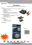
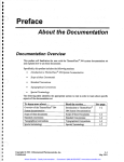
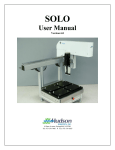
The StackLink (Figure 1) is an automated microplate stacker, which also drives a high
speed, modular and expandable track system that delivers lab ware to multiple laboratory
instruments. A part of LabLinx track system, the StackLink is capable of handling up to
120 (60 x 2 stacks) 96-well, 384-well or 1536-well standard microliter plates.
The StackLink includes Hudson Robotics’ SoftLinx software, which provides an easy-touse interface to coordinate the LabLinx operation with other automated instruments.
Softlinx is written in the Visual Basic for Applications programming language and can
run on Windows Vista, Windows 7. The StackLink can be interfaced with readers,
washers, liquid handlers, labelers, pipettors, etc.
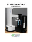
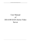
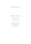
The StackLink is equipped with optional expandable tracks, known as TrackLinks
(Figure 2), as well as up to 8 plate-stop modules called StopLinks (Figure 3). The
StopLink uses proximity sensors in line with quick plate catching “fingers” to stop and
position the microplate in precise locations.
Figure 1
StackLink User Manual
Hudson Robotics, Inc.
1
Tracklink
StopLink
Figure 2
Figure 3
StackLink w/ TrackLink and StopLink options
Figure 4
Computer Requirements
The following are recommended for proper operation of the PlateCrane EX and Softlinx:
Operating System: Windows XP SP3, Windows XP x64, Windows Vista
32, Windows Vista 64, Windows 7 32, Windows 7 64
2.5GHz Quad Core Pentium processor or faster, 4GB RAM or higher, CDRom drive, 2 available USB Ports
3GB MB of free disk space available
.NET Framework 4.0
StackLink User Manual
Hudson Robotics, Inc.
2
The Computer has the recommended number of working serial ports (You
can Purchase USB-to-serial convertors from Hudson Robotics If NeededPlease contact your local Sales Manager)
Power and communication cables for third party devices being connected
have been verified
External Air Requirements
60 PSI compressed air
StackLink User Manual
Hudson Robotics, Inc.
3
Chapter 2-Installation
Unpacking the StackLink
WARNING- -
Power switch must be turned OFF during entire installation procedure
DO NOT loosen or tighten any screws or touch parts not specified in the
instructions
Never force any component to fit
The StackLink weighs 30 lbs. and should be handled with care to avoid mishaps
Overview:
1. Remove StackLink from carton (Once you have a firm grasp on the unit gently lift the
unit straight up out of the carton. Make sure that the StackLink is separated from the
shipping foam)
2. Unpack any other accessories (TrackLinks, StopLinks, Alignment Bases) shipped
with the unit.
3. Position the StackLink on the Bench, with the flat side of StackLink facing towards
the end user. Unless limited by installation or layout.
4. Install Stack(s) into stack positions 1 and 2 on the unit. Make sure the stacks are
securely positioned on the unit. The open top section of the stacks should face out
and away from each other. This allows for the end user to remove or add plates easily.
5. Install any TrackLinks included in the system. First, remove the two clamp bars from
the StackLink. Slowly slide the TrackLink into the StackLink, make sure that the
gear on the StackLink and TrackLink align correctly. Then secure the TrackLink by
screwing down the clamp bars back into the StackLink.
6. Position any StopLinks where required by fastening them to the side of the track with
the provided Phillips head screws. Plug the modular plug into the desired port on the
side of the StackLink.
7. Position the plate stops across from the StopLinks and secure them with the provided
Phillip head screws. These plate stops prevent the plate from being pushed off of the
track when the StopLinks close.
8. Connect 1/4 “air line tubing supplying a minimum 60psi of compressed air to the
regulator located on the rear of the instrument.
9. Connect power cord and communication cable to the rear of the StackLink
10. Install Softlinx Software (see Chapter 3)
NOTE:
Please refer to the parts list to verify that all parts are included in the StackLink
carton. If any parts are missing, please contact Hudson Robotics.
StackLink User Manual
Hudson Robotics, Inc.
4
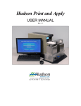
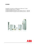
DO NOT DISCARD the StackLink carton. This carton has been specially
created for this product and must be used for any additional shipping of the
instrument to prevent damage.
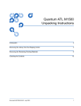
Power Cord Location
Air Inlet
Communication Cable location
Figure 5
Parts List
The StackLink carton(s) should include the following:
StackLink
2 Extruded Stacks (double Stacks optional)
Power cord
Communication cable
User Manual (This document)
CD containing Softlinx and interfaces
StopLink(s) (optional)
Modular cord for each StopLink (optional)
Alignment Bases for instrument(s) (optional)
TrackLinks (optional)
TrackLink connection assemblies (for linking multiple tracks) (optional)
Clamp Bars (for securing TrackLinks to StackLink unit)
StackLink User Manual
Hudson Robotics, Inc.
5
Setting up the StackLink
Remove the StackLink from the carton and carefully remove the protective plastic
covering.
Un-wrap any TrackLinks and/or StopLinks included.
Remove the Stacks from the carton, then remove the stack from the packaging
Install the supplied Stacks on the StackLink securely.
Setting up the TrackLink(s)
Position the TrackLink into either side of the StackLink and insert the track so the
groves match and fit into place (Figure 7).
NOTE: Be sure the TrackLink and StackLink gearing is properly positioned and
aligned for correct operation
Secure the track with the included Clamp Bars (Figure 11). Repeat if connecting
an additional TrackLink if required.
Secure the TrackLink to any instrument nests.
NOTE: Calibration and/or origin adjustments may need to be set for these
instruments. (I.E. PlateCrane positions, Micro10 dispensing origin, etc.)
Figure 7
StackLink User Manual
Hudson Robotics, Inc.
6
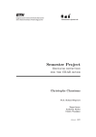
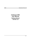
Setting Up StopLink(s)
Position the StopLink in the desired location on the track and secure its position
with the supplied Phillips head screws. (Figure 12)
Connect modular plugs of the black coiled cable into both the StopLink and the
desired port on the side of the StackLink (Figure 9/10).
Adjustments may be needed depending on the size and type of plates used. Place
a plate on the track in front of the StopLink sensor to activate the fingers. Loosen
the 2 hex screws on the StopLink (Figure 8) and adjust the width of the sides so
the plate is secure between the fingers without any movement.
Adjustment
screws
Figure 8
StopLink Positions 1-4
Figure 9
StackLink User Manual
Hudson Robotics, Inc.
7
StopLink Positions 7-10
Figure 10
Clamp Bars securing tracks
Figure 11
StackLink User Manual
Hudson Robotics, Inc.
8
Figure 12
Phillips Head
screws positioning
Connect Power Cord & Communication Cable:
Note: Power switch must be turned OFF
Remove power cord and communication cable from StackLink carton.
On the rear side of the base unit housing connect one end of the 9-pin to 9-pin serial cable
(see Figure 7), and attach the other end into COM1 port on Host Computer.
Plug power cable into the StackLink's AC inlet located on rear side of the base unit
housing (see Figure 7).
Note: The communication cable & power cord should be securely plugged into the
StackLink and computer.
Switching AC Line Voltage 110VAC/220VAC
The power supplies installed in the unit are switching power supplies. That means they
are able to handle both 110VAC and 220VAC without any changes to their configuration.
The Run the StackLink on 220VAC perform the following:
Make sure the unit is powered off
Install the power cord that is supplying the 220VAC
Turn on unit
StackLink User Manual
Hudson Robotics, Inc.
9
CHAPTER 3-StackLink Software
Brief Description of Software
Hudson's standard StackLink application software (SoftLinx) can be found on one (1)
installation CD. This CD can be loaded onto any PC running Microsoft's Windows 98
SE, NT 4.0. w\ service pack 6, 2000, or XP. This software provides a complete set of
utilities to run the StackLink and any instruments purchased by the end user. Hudson’s
LabLinx is an easy-to-use, dynamic scheduling software program for control of
integrated lab automation workcells and systems. LabLinx includes a multitasking core
executable combined with device interfaces that are written in VBA (Visual Basic for
Applications). The user sets up a method using a drag-and-drop icon-based method
editor.
How to Install Software
Turn computer ON. Start Windows, if it's not already running.
Insert CD into CD-ROM drive, and then close the drawer
The CD has an auto run function, so the installation of the software is automatic
If the CD does not auto run, then click on the Start menu
Click the run menu, then type in the location of the CD and Setup.exe
(E:\Setup.exe)
Then click OK to start installation
Follow instructions as prompted to complete the installation.
After installing LabLinx, open it by clicking the shortcut installed on your desktop.
StackLink User Manual
Hudson Robotics, Inc.
10
Configuring a Workcell
Click on the Configure Workcell icon on the screen.
Click and drag the corresponding icon for each instrument into the workcell and
select the communication port the instrument is assigned to.
Click the Return to Run View icon (same as Configure Workcell) and you will be
prompted to save the workcell you have just created.
StackLink User Manual
Hudson Robotics, Inc.
11
Click the Setup button under the StackLink icon.
Stack 1
Stack 2
Select each StopLink position(s) with the corresponding side of the TrackLink
you have secured the StopLink to.
StackLink User Manual
Hudson Robotics, Inc.
12
NOTE: Be sure to match the correct instrument nest name from the pull down
menu or errors will occur when attempting to run methods.
HINT: Clicking on the Test Button will allow you to test the operation of LabLinx
by allowing you to dispense, return, and shift plates.
Setting Up Plate Parameters
Entering correct dimensions for the plates you will be using is used only for the proper
handling of those plates by the PlateCrane EX as it automatically adjusts its positions for
each different plate-type used in every method based solely on the information entered
into that plate’s definition.
While not running a method, the user may click on the ‘Plates’ button located just above
the first configured instrument panel on SoftLinx’ ‘Run’ screen. The following ‘Plate
Setup’ form will be displayed:
Figure 13
StackLink User Manual
Hudson Robotics, Inc.
13
Click on the ‘Edit Plate’ button to change the parameters of a previously defined plate, or
click on ‘New Plate’ to create a new plate definition. Then, the following form will be
displayed:
Figure 14
HINT: The only parameter value important to the StackLink is:
StackLink Delay (msec)
The delay time (in milliseconds) it takes the Plate Seats to close after the stack
elevator begins to descend.
This is used when using microplates with special extrusions that may interfere
with dispensing.
StackLink User Manual
Hudson Robotics, Inc.
14
CHAPTER 5-StackLink Components
DriveLink System
The StackLink’s elevator and plate handling components use mostly pneumatic contols to
function. The LabLinx system uses a variety of sensors to feedback the plates
positioning to the unit’s computer controller. The StackLink also uses a powerful bidirectional belt and pulley system driven by a reversible 110 VAC motor to shift plates
along the LabLinx track.
Stacks
The standard StackLink includes two extruded aluminum stacks. Each stack can hold up
to 30 standard-height microliter plates. The stacks are from an aluminum extrusion for
rigidity and precision. The stacks are held in position by plastic guide blocks on the
StackLink. Double stacks are also available to increase plate capacity.
Power Cord/Communication Cable Connection
The power cord plugs into the AC inlet on the rear of the StackLink. Input power is
either 120V or 230V, 50 or 60 Hz. The communication cable is connected from the rear
of the StackLink to the chosen serial port on the computer (usually COM 1).
Power Switch
The power switch is located on the back plate with the power cord and communication
cable (see Figure 5). It has a 0 and 1 engraved on it to show the OFF and ON power
condition of the StackLink. StackLink power is ON when the switch is pressed in the 1
position and PWR LED on the top of the StackLink is illuminated.
Optional Components
The following are additional items available for the StackLink:
Double Stacks -- Expands StackLink capacity of up to 120 microliter plates (4
stacks).
TrackLink (24” & 36”)—Linkable tracks that transport plates to various locations
of the workcell.
StopLink (up to 8) – Modules that catch and release microplates along the
TrackLink path to allow other instruments to access these plates.
StackLink User Manual
Hudson Robotics, Inc.
15
Instrument alignment bases – Enables the instruments to be locked to the
TrackLink so they will not shift.
DriveLink: A separate instrument that provides the additional power needed to
drive the TrackLink system if additional lengths of track are required.
StackLink User Manual
Hudson Robotics, Inc.
16
CHAPTER 6-Hardware Specifications
General
Note: Specifications are subject to change without notice.
Plate Capacity:
Plate Storage Device:
Housing Material:
Gripper Material:
DriveLink length:
Standard-- Up to 30 plates without lids or 25 plates
with lids.
Additional-- Up to 120 plates without lids or up to 100
plates with lids.
2 removable stacks (Double Stacks available)
Painted steel covering cast aluminum housing.
Black anodized aluminum; textured neoprene rubber
inserts.
15 inches
TrackLink
Gearing:
Pulley System:
Available Lengths:
Maximum Track Length:
Guarded power transmitting shaft assembly
2 - 3/16” wide 1/5 pitch timing belts
24” and 36” tracks
159” (up to 4 -36” tracks) for 1 StackLink
StopLink
Plate Detection:
Stopping Mechanism:
Communication:
Photoelectric sensor
2 plate stop fingers (left & right) operated by rotary
solenoids
13” coiled cord (8 pos RJ-12 modular plug)
Mechanical Description
DriveLink Motor:
DriveLink Gearhead:
Elevator Lift:
Plate Gripper:
Pressurized Air Supply:
AC reversible motor 110V 60Hz
Frame #2, 200 RPM
Pneumatic lift cylinder assembly
Pneumatic fired gripper pads (10mm bore, 5mm stroke)
Regulator with filter and gauge (1/4” air supply fitting)
StackLink User Manual
Hudson Robotics, Inc.
17
Internal Air Tubing:
Stack Present:
Plate Sensor:
Seat Opener:
Plate Stops:
Parflex Polyurethane tubing 1/16” ID, 1/8” OD
Parflex Polyurethane tubing 2.4mm ID, 4.00mm OD
Proximity switch
Type MH photoelectric sensor
Double rod air cylinder, 10mm x 10mm
4 – (pneumatic firing) extruding pins
Dimensions
Height:
Weight:
26.25” (incl. extruded stack)
30 lbs.
Electrical
Power Input:
Fuses:
Grounding:
Computer Interface:
120V / 230V AC, 50/60 Hz
(Determined by position of fuse holder)
For 120V / 230V
One 2A Time Delay, 5mm x 20mm
(.205 in. x .787 in.)
Through the power cord, must be properly earth
Grounded
RS-232 serial cable
Environmental
Operating Temperature:
Operating Humidity:
Storage Temperature:
Altitude:
Ventilation
15 to 40C (59 to 104F)
0 to 85%, no condensation
-20 to 65C (-4 to 149F)
Up to 2000m
Fan requires +2” of free space in front of it
Indoor Use Only
StackLink User Manual
Hudson Robotics, Inc.
18
CHAPTER 7-Maintenance
Maintenance
WARNING- -
Qualified personnel can perform all maintenance procedures in this
manual. Only Hudson representatives should perform any maintenance
not discussed in this manual.
Gloves should be worn during any cleaning procedure.
Cleaning the StackLink
Note: DO NOT use/spray abrasive cleaners onto the StackLink.
Clean the outside surfaces of StackLink and/or TrackLink using cloth or sponge
dampened with alcohol, water, or mild glass cleaner.
Clean finger pads of gripper with alcohol or other residue-free solvent.
Clean any spills on the StackLink, TrackLink, or StopLink immediately.
Only clean the exterior of the unit. DO NOT remove instrument covers to clean
inside.
Never allow water or fluid to leak inside the StackLink.
Change the Fuse(s)
Fuses burn out occasionally and must be replaced. The following fuses are used with the
StackLink:
Metric: 1 x 2 amp, 5 x 20 mm Time Delay Fuse
WARNING- -
Be sure the power to the StackLink is OFF and the power cord is
unplugged from the instrument or power source before proceeding with
the following instructions.
Turn the StackLink OFF and remove the power cord from the AC inlet on the back
of the unit.
StackLink User Manual
Hudson Robotics, Inc.
19
Using a small flat head screwdriver, gently pry the fuse holder tray away from its
housing to access the fuses. The Fuse holder door swings down.
Remove the blown fuse. Replace it with the spare fuse.
Slide the fuse holder tray back into the AC inlet until it clicks. Make sure when reinstalling the holder the AC line voltage reads the correct way on the inlet
Reconnect the power cord to the StackLink and reconnect all other cables
previously disconnected.
Verify correct fuse replacement by turning the StackLink switch to ON position-the light will illuminate immediately.
Location of fuse
holder tray
Figure 15
StackLink User Manual
Hudson Robotics, Inc.
20
Appendix A:
Hudson's LabLinx Communications and Command Set
Version 1.0
Hudson's LabLinx System is designed to respond to a simplified set of ASCII commands
to allow any user program capable of reading/writing via an RS-232 port or TCP/IP
connection to exercise all the features of the LabLinx Units.
Protocol Description
For RS-232 communication, a single RS-232 port is used to communicate to each
LabLinx device attached to the system.
The RS-232 connection for the LabLinx system operates with the following
communication specifications:
Baud Rate:
38400
Data Bits:
8
Stop Bits:
1
Parity:
None
Handshake:
None
Device Type:
DCE
Connector:
9-pin, female
For TCP/IP communication, each unit must have a unique IP address assigned. This can
be accomplished with the SETIP command. The computer should then connect to this IP
address on TCP port 7.
LabLinx unit commands have the following format:
{command}[{parameter1},{parameter2},…]<13><10>
The {command} portion is the actual command to be executed by the receiving unit.
This may be followed by a comma-separated list of parameters as specified in the
individual command descriptions.
All LabLinx commands are terminated by a carriage return / line feed combination
(ASCII characters 13 and 10). The command is then delivered to the addressed unit,
which parses, validates, and executes the requested command before returning a
response. Commands may be sent to units while they are processing other commands.
Each unit can queue up to 10 commands. The behavior when the queue is overloaded is
StackLink User Manual
Hudson Robotics, Inc.
21
currently unspecified. There is currently no message indicating that the command queue
has been overloaded.
The following example would send the DISPENSE command, with an argument
indicating to dispense from Stack 1.
DISPENSE 1<13><10>
Command Responses
The controller will echo every byte of the command back to the sender as it is received.
Upon detecting the two bytes <13><10>, the controller will execute the command. Upon
completing execution, the controller will respond in one of two ways:
1. For query commands, where a data response is required, it will return:
{data response}<13><10>
2. For action commands or invalid queries, it will return:
{error code} {error description}<13><10>
If an action is requested, or an error occurs the response will be a 4 digit error code, a
space (ASCII character 32), and a short description of the error that occurred. A response
of “0000 Success" represents a correctly executed command. Other responses will
indicate an error.
As examples:
1. Valid query command:
Command:
Echo:
Response:
READINPUT 0,2<13><10>
READINPUT 0,2<13><10>
0<13><10> (i.e., input no. 2 is OFF)
2. Valid action command:
Command:
Echo:
Response:
CLOSE <13><10>
CLOSE <13><10>
0000 Success<13><10> (i.e., action successfully executed)
3. Invalid query command ("WASHER" is an unknown position):
Command:
GETPOINT WASHER<13><10>
Echo:
GETPOINT WASHER<13><10>
Response:
0002 Invalid Parameter<13><10> (invalid point name)
Note: If any command contains an error, the StackLink sends the response immediately,
otherwise the response is sent at the completion of execution.
StackLink User Manual
Hudson Robotics, Inc.
22
StackLink Command Set
The StackLink Unit recognizes the following commands:
1. ACKNOWLEDGESEND
The ACKNOWLEDGESEND command is used to indicate that a plate transfer
between two conveyor-based LabLinx units has been completed, and that the
recipient of the command should turn off the conveyor. See the
RECEIVEPLATE and SENDPLATE commands for more information.
Example:
Command:
Response:
ACKNOWLEDGESEND<13><10>
0000 Success<13><10>
2. DISPENSE [Stacks]
DISPENSE will cause the StackLink to dispense a plate from the specified stacks.
The Stacks parameter is bit mask indicating the stacks to dispense from. Bit 1
indicates Stack1, bit 2 indicates Stack2. Currently only values from 1-3 are
accepted. Plates under one of the stacks when this command is issued will remain
in place at the completion of the command.
Example:
Command:
Response:
DISPENSE 2<13><10>
0000 Success<13><10>
3. GETCONFIG
The GETCONFIG command returns a bit mask indicating the currently available
positions on the StackLink unit. There are 10 possible positions, allowing
configuration values between 0 and 1023. Normally bits 5 and 6 will be active
indicating the presence of Stacks 1 and 2. Other bits may be active depending on
the connected TrackLink and StopLink units. This value is set using the
SETCONFIG command.
Example:
Command:
Response:
GETCONFIG<13><10>
112<13><10>
4. GETDISPENSEDELAY
GETDISPENSEDELAY returns the additional time in milliseconds that the plate
seats will be held open when dispensing a plate. This allows the stacker to
StackLink User Manual
Hudson Robotics, Inc.
23
dispense double-flanged or otherwise oddly shaped plates. This time is set using
the SETDISPENSEDELAY command. This time should be 0 for most plates.
Example:
Command:
Response:
GETDISPENSEDELAY <13><10>
0<13><10>
5. GETIP
GETIP returns the current IP address of the unit.
Example:
Command:
Response:
GETIP<13><10>
10.1.1.5<13><10>
6. GETMOVETIME
GETMOVETIME returns the current number of seconds the StackLink waits for
labware to arrive at a location before returning a failure to move the labware.
This value is set using the SETMOVETIME command.
Example:
Command:
Response:
GETMOVETIME<13><10>
10<13><10>
7. GETPOSNAME {Position Number}
GETPOSNAME returns the name assigned to the indicated position number.
This command allows applications to assign useful names to various StackLink
position numbers. These names are not currently used in any StackLink
commands other than the GETPOSNUM command.
Example:
Command:
Response:
GETPOSNAME 5<13><10>
Stack1<13><10>
StackLink User Manual
Hudson Robotics, Inc.
24
8. GETPOSNUM {Position Name}
GETPOSNUM will return the position value associated with the specified
position name.
Example:
Command:
Response:
GETPOSNUM Stack1<13><10>
5<13><10>
9. GETSTOPDELAY
GETSTOPDELAY will return the number of milliseconds before the stops will
capture a plate when the plate is placed on the track by another instrument.
Example:
Command:
Response:
GETSTOPDELAY<13><10>
300<13><10>
10. LISTPOINTS
The LISTPOINTS command returns a list of the currently available positions and
the names assigned to them. The line “End of List” is returned to indicate the end
of the command.
Example:
Command:
Response:
LISTPOINTS<13><10>
5: Stack1<13><10>
6: Stack2<13><10>
7: MyWasher<13><10>
End of List<13><10>
11. MOVEPLATE {Start}, {End}
The MOVEPLATE command moves a plate between the indicated start and end
position numbers. The positions must be available according to the current
configuration. There must be labware in the start position. And the path between
the start and end positions must be clear. If any of these conditions is not met an
appropriate error will be returned.
Example:
Command:
Response:
MOVEPLATE 5,7<13><10>
0000 Success<13><10>
StackLink User Manual
Hudson Robotics, Inc.
25
12. NAMEPOS {Position Number}, {Position Name}
The NAMEPOS command assigns the indicated name to the indicated position
number.
Example:
Command:
Response:
NAMEPOS 7, MyWasher<13><10>
0000 Success<13><10>
13. READINPUT {Card Number}, {Input Number}
READINPUT returns the current state of the input located at the indicated I/O
card number and input number. A 0 indicates the input is not active, a 1 indicates
that the input is active.
Example:
Command:
Response:
READINPUT 0,0<13><10>
0<13><10>
14. RECEIVEPLATE {Direction}, {End}
The RECEIVEPLATE indicates that the StackLink should activate its conveyor
and begin looking for labware to arrive at the indicated end location. The
direction parameter indicates which direction to turn the conveyor. A 1
designates forward motion, and a 0 indicates reverse motion. The conveyor will
turn off when the labware arrives at the indicated location, or the current move
time has elapsed. See the commands SENDPLATE and
ACKNOWLEDGESEND for more information.
Example:
Command:
Response:
RECEIVEPLATE 1,6<13><10>
0000 Success<13><10>
15. RELAYOUT {Card}, {Relay}, {State}
The RELAYOUT command activates the indicated relay on the indicated relay
card. A state of 1 indicates that the relay should close. A 0 indicates that the
relay should open.
Example:
Command:
Response:
RELAYOUT 1,2,1<13><10>
0000 Success<13><10>
StackLink User Manual
Hudson Robotics, Inc.
26
16. RETURN [Stacks]
RETURN will place plates located under the indicated stacks into the stacks. The
Stacks parameter is a bit mask indicating the stacks to return to. Omitting the
Stacks parameter causes the StackLink to return any plates under both stacks.
Plates under stacks not specified in the mask will remain at their current location.
Example:
Command:
Response:
RETURN 1<13><10>
0000 Success<13><10>
17. SENDPLATE {Direction}, {Start}
SENDPLATE indicates the StackLink should send the labware located at the start
position off the conveyor in the indicated direction. A 1 indicates forward
motion. A 0 indicates reverse. The conveyor remains active until an
ACKNOWLEDGESEND command is received.
Example:
Command:
Response:
SENDPLATE 1,5<13><10>
0000 Success<13><10>
18. SETCONFIG {Configuration}
SETCONFIG sets a bit mask indicating the available positions on the StackLink unit.
There are 10 possible positions allowing values between 0 and 1023.
Example:
Command:
Response:
SETCONFIG 112<13><10>
0000 Success<13><10>
19. SETDISPENSEDELAY {Time}
SETDISPENSEDELAY sets the additional time in milliseconds that the plate seats
will be held open when dispensing a plate. This allows the stacker to dispense
double-flanged or otherwise oddly shaped plates. This time should be 0 for most
plates.
Example:
Command:
Response:
SETDISPENSEDELAY 0<13><10>
0000 Success<13><10>
StackLink User Manual
Hudson Robotics, Inc.
27
20. SETIP {IP Address}
SETIP will set the IP address of the unit. This change is immediate and may cause
loss of communication if used during a TCP/IP session.
Example:
Command:
Response:
SETIP 10.1.1.5
0000 Success <13><10>
21. SETMOVETIME {Timeout}
SETMOVETIME sets the number of seconds the StackLink waits for a plate to
arrive at its destination before returning an error.
Example:
Command:
Response:
SETMOVETIME 30<13><10>
0000 Success<13><10>
22. SETSTOPDELAY {DelayTime}
SETSTOPDELAY sets the amount of time the StackLink will wait before closing the
stops if a plate is placed on the track by another instrument. The DelayTime is in
milliseconds.
Example:
Command:
Response:
SETSTOPDELAY 300<13><10>
0000 Success<13><10>
StackLink User Manual
Hudson Robotics, Inc.
28
23. SHIFT {Direction}, [Positions], [Receive]
The SHIFT command will move plates one position in the indicated direction. A
Direction of 1 indicates forward motion. A Direction of 0 indicates reverse motion.
If the Positions parameter is included, only the plates at the indicated positions will be
shifted. If the Positions parameter is omitted, all plates will be shifted. Issuing a
command to shift the plate located at the end position off of the StackLink will cause
the unit to behave as if a SENDPLATE command had been issued. The StackLink
will shift the indicated plates, and then continue to run the conveyor until an
ACKNOWLEDGESEND command is received. If the Receive parameter is
included, it will indicate whether or not the StackLink should expect to receive a plate
from an adjacent unit. The plate will always be received into the end position of the
StackLink. A Receive value of 1 indicates that a plate is expected. A Receive value
of 0 indicates no plate is expected.
Example:
Command:
Response:
SHIFT 1,112,1<13><10>
0000 Success<13><10>
24. VERSION
VERSION returns the unit firmware version.
Example:
Command:
Response:
VERSION<13><10>
StackLink Unit v0.2<13><10>
25. WRITEOUT {Card}, {Output}, {State}
WRITEOUT changes the state of the indicated output on the indicated I/O card.
A state of 1 indicates the output should be active. A 0 indicates the output should
become inactive.
Example:
Command:
Response:
WRITEOUT 0,0,1<13><10>
0000 Success<13><10>
StackLink User Manual
Hudson Robotics, Inc.
29
Error Code Description
The PlateCrane controller will report one of the following response codes at the
completion of each command:
General Errors:
00
Success
01
Unrecognized Command
02
Invalid Parameter
03
Bad Echo From Unit
StackLink Errors:
0100 Path is blocked.
0101 Nothing to move
0102 Position not available
0103 Failed to move plate
0104
0105
0106 Invalid position name
0107
0108
0109
0110 Elevator Jammed
0111 Elevator Blocked
0112 No Plate Dispensed
0113 Failed to Return Plate
StackLink User Manual
Hudson Robotics, Inc.
30