1
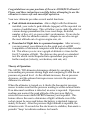
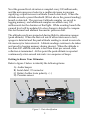
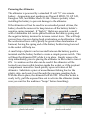
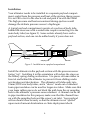
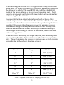
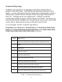
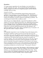
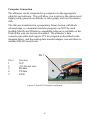
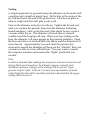
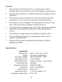
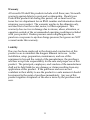
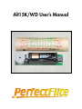
Alt15K/WD User’s Manual
Alt15K/WD User’s Manual
A subminiature altimeter with audible peak reporting
and full flight logging/download capability.
15 Pray Street
Amherst, MA 01002
Voice (413) 549-3444
FAX (413) 549-1548
URL: www.perfectflite.com
Sales: [email protected]
Support: [email protected]
Contents
Preface ....................................................................... 1
Theory of Operation .................................................... 1
Preliminary Setup
Getting to know your altimeter .............................................
Powering the altimeter .......................................................
Installation
Payload compartment setup .................................................
Sampling hole size chart .....................................................
Numerical reporting method ................................................
Operation
Sequence of events ...........................................................
Computer connection .........................................................
Ground testing ................................................................
2
3
4
5
6
7
8
9
Cautions ................................................................... 10
Specifications ............................................................ 10
Warranty .................................................................. 11
Congratulations on your purchase of the new Alt15K/WD altimeter!
Please read these instructions carefully before attempting to use the
altimeter to insure safe and successful operation.
Your new altimeter provides several useful functions:
Peak altitude determination. After a flight with the altimeter
installed, your rocket’s peak altitude (apogee) will be reported via
a series of audible beeps. This will allow you to study the effect of
various design parameters (fin/nose cone shape, fin airfoil,
number of fins, etc.) on your rocket’s performance. It can also be
used by clubs for altitude contests - compete to see who can get
the most altitude out of a given engine size, etc.
Download of flight data to a personal computer. After recovery,
you can connect your altimeter to the serial port of an IBM
compatible or Macintosh computer with the optional data transfer
kit. This allows you to view a graph of altitude vs. time for the
first 5.7 minutes of flight. The data are also saved as a standard
text file which can be imported into spreadsheet programs for
further analysis (velocity, acceleration, sink rate, etc).
Theory of Operation
The Alt15K/WD altimeter determines altitude by sampling the
surrounding air pressure during flight and comparing it with the air
pressure at ground level. As the altitude increases, the air pressure
decreases, and the onboard microprocessor converts the pressure
difference to altitude.
When the altimeter is turned on, it checks the barometric pressure
sensor to make sure that the pressure reading is within normal limits.
If an abnormal condition is detected, an error is reported. If pressure
readings are normal, the peak altitude of the previous flight is
retrieved from nonvolatile EEPROM memory and reported. This
feature allows the user to determine a flight’s altitude even if the
rocket cannot be recovered before the battery is depleted (approximately 24 hours). After the previous flight altitude is reported, the
altimeter waits 15 seconds for the electronics to stabilize, then emits a
periodic “beep’ to indicate readiness for launch.
1
Next the ground level elevation is sampled every 100 milliseconds,
and the microprocessor looks for a sudden decrease in pressure
signifying a rapid increase in altitude (launch detection). When the
altitude exceeds a preset threshold (80 feet above the ground reading),
launch is detected. The previous 8 altitude samples are saved to
logging memory, and additional samples are added every 100
milliseconds for the duration of the flight. While awaiting launch the
ground level will be updated if a slow change is detected to compensate for thermal and ambient barometric pressure drift.
The altitude results are inspected during flight to determine apogee
(peak altitude). When the derived rate of ascent decreases to zero,
apogee is detected and the peak altitude reading is stored in nonvolatile memory for later retreival. Altitude readings continue to be taken
and saved in logging memory during descent. When the altitude is
less than 300’ and the sink rate is less than 4 feet per second, data
collection is terminated. At this point the peak altitude is reported
continuously at ten second intervals via a sequence of beeps.
Getting to Know Your Altimeter:
Refer to figure 1 below to identify the following items:
A)
B)
C)
D)
Audio beeper
Serial data I/O connector
Battery holder (note polarity +/-)
Pressure sensor
Figure 1: Parts identification
2
Powering the Altimeter
The altimeter is powered by a standard 12 volt “N” size remote
battery. Appropriate part numbers are Duracell MN21/23, GP A23,
Energizer A23, and Radio Shack 23-144. Observe polarity when
installing the battery to prevent damage to the altimeter.
If the altimeter will not be used for an extended period of time, the
battery should be removed to keep tension off the battery holder’s
negative spring terminal. If “high G” flights are expected, a small
wad of aluminum foil can be placed between the battery spring and
the negative battery terminal to increase contact force. This will help
prevent loss of power during hard acceleration or decelleration. Since
the acceleration force will typically be greater than deceleration at
burnout, having the spring end of the battery holder facing forward
in the rocket will help too.
A small strip of plastic can be inserted between the battery positive
terminal and the battery holder to create a simple power switch. This
will keep the altimeter OFF while it is in place. Simply remove the
strip immediately prior to placing the altimeter in the rocket to turn it
ON. A variation on this idea can be used if the altimeter will be
located in an inaccessible location inside the rocket, or if the payload
compartment cannot be closed quickly upon activation of the
altimeter. Substitute a piece of monofilament fishing line for the
plastic strip, and route it out through the pressure sampling hole.
With the line in place, the altimeter will be OFF. When the rocket is
ready to fly, pull the exposed line out to activate the altimeter (make
sure you wait for the readiness “beeps” before launching).
plastic tab switch
plastic cord switch
3
Installation
Your altimeter needs to be installed in a separate payload compartment, sealed from the pressure and heat of the ejection charge gasses.
It is not OK to tie it to the shock cord and pack it in with the chute!
The high pressure and heat encountered during ejection would
damage the delicate pressure sensor’s diaphragm.
A typical payload compartment consists of a section of body tube
behind the nosecone with a sealed tube coupler connecting it to the
main body tube (see figure 2). Some rockets already have such a
payload section, and one can be added easily if yours does not.
Loose fit
Glue
Tight fit
Wadding
Sampling hole
Altimeter
Figure 2: Installation in a payload compartment
Install the altimeter in the payload section with the pressure sensor
facing “up”. Installing it in this orientation will reduce the stress on
the battery spring during acceleration. Use pieces of foam rubber in
front of and behind the altimeter to prevent it from shifting under
acceleration and deceleration. The altimeter will slide easily into
18mm/BT20 size body tubes, and a “sleeve” made out of standard
foam pipe insulation can be used for larger size tubes. Make sure that
your foam rubber pieces do not block the path from the air sampling
hole to the altimeter’s pressure sensor element. A channel can be cut
in pipe insulation for this purpose; make sure that the channel lines
up with the sampling hole and the sensor’s air inlet. Your payload
section should close securely so that the altimeter is not “ejected”
upon motor burnout deceleration or chute deployment shock.
4
When installing the Alt15K/WD in larger rockets it may be easiest to
add a short (~3” long) section of BT20 tube with padded end plugs for
the altimeter to ride in. The short BT20 tube could be glued to the
inside of the larger airframe or to a plywood mounting plate. Don’t
forget to incorporate vent holes in the inner tube to allow external air
pressure to get to the altimeter.
You must drill a clean-edged hole in the payload section to allow
outside air pressure to be sampled by the altimeter. This hole should
be as far away from the nosecone and other body tube irregularities as
possible (3X the body tube diameter or more) to minimize pressure
disturbances being created by turbulent airflow over the body tube.
Sand the area around the hole as necessary to eliminate flashing or
raised edges. Exact sizing of the hole is not critical, refer to the table
below for suggestions.
While not strictly necessary, the single sampling hole can be replaced
by several smaller holes distributed around the airframe’s circumference. This will minimize the pressure variations due to wind currents
perpendicular to the rocket’s direction of travel.
Diameter
Length
Hole Size
1”
5”
.031” (1/32”)
1.6”
6”
.047” (3/64”)
2.1”
6”
.078” (5/64”)
2.1”
12”
.156” (5/32”)
3.0”
12”
.219” (7/32”)
3.0”
18”
.344” (11/32”)
Other “D”
Other “L”
H=D*L*.006
Table 1 - Payload Section Size vs. Sampling Port Hole Size
5
Numerical Reporting
Numbers are reported as a long beep (separator), followed by a
pattern of shorter beeps. All numbers are reported using up to five
digits – a series of beeps for the first digit (tens of thousands of feet), a
short pause, another series of beeps for the next digit (thousands of
feet), etc. Leading zeroes are suppressed: 1,582 feet would be
represented with four digits, not five digits as in 01582. Ten beeps are
used to indicate the number zero (if zero beeps were used, you would
not be able to differentiate between 2200 feet and 22 feet!).
As an example, 12,560’ would be reported as:
long beep-pause-beep-pause-beep-beep-pause-beep-beep-beep-beepbeep-pause-beep-beep-beep-beep-beep-beep-pause-beep-beep-beepbeep-beep-beep-beep-beep-beep-beep-long pause
Digit
Reported as:
0
beep-beep-beep-beep-beep-beep-beep-beep-beep-beep
1
beep
2
beep-beep
3
beep-beep-beep
4
beep-beep-beep-beep
5
beep-beep-beep-beep-beep
6
beep-beep-beep-beep-beep-beep
7
beep-beep-beep-beep-beep-beep-beep
8
beep-beep-beep-beep-beep-beep-beep-beep
9
beep-beep-beep-beep-beep-beep-beep-beep-beep
Table 2 - numerical beep sequences
6
Operation
To insure proper operation of your altimeter you must follow a
specific sequence of events. If you launch before the altimeter is
ready, ground level will not be sampled properly and the altitude
readings will be wrong.
Sequence of events
Prepare your rocket and install the engine before setting up the
altimeter. Insert a battery to turn the altimeter ON. The altitude of
the previous flight will be reported. If you hear a continuous tone
instead, the altimeter’s built-in self test is indicating a problem. Do
not attempt to launch if this condition exists!
After the previous flight altitude is reported, the altimeter will be
silent for 15 seconds while the electronics are stabilizing and ground
level is being tracked. The altimeter needs to be inserted into the
rocket and the payload compartment sealed before this time elapses.
When the 15 second stabilization period ends the altimeter will
indicate readiness with a short “beep” repeated every 1.5 seconds. At
this point the rocket is ready to launch.
Note:
If the payload compartment is not closed before the periodic beeping starts,
the altimeter should be removed, turned OFF and then back ON, and
reinstalled. If you close the payload compartment when the altimeter is in
the periodic beep phase (awaiting launch), it is likely that closing the payload
compartment will inadvertently trigger the altimeter and produce an
erroneous reading. This is due to the fact that when you close the compartment you will pressurize the interior of the compartment, and when the
pressure diminishes through the sampling hole the altimeter will interpret
this as a rapid ascent (launch). If it is not convenient to install the altimeter
in the time allotted, you can arrange an external activation switch with
monofilament fishing line as discussed under “Powering the Altimeter”.
When you recover your rocket, the altimeter will be beeping to report
the peak altitude attained. Since this reading is saved in nonvolatile
memory, you can safely turn the altimeter OFF at any time. If you
want to retrieve the altitude reading at a later time, simply turn the
altimeter back on and the altitude will be reported again.
7
Computer Connection
The altimeter can be connected to a computer via the appropriate
cable kit and software. This will allow you to retrieve the entire saved
flight profile, generate an altitude vs. time graph, and save the data to
disk.
The data are transferred in a proprietary binary format with block
acknowledge, so a terminal emulator program can NOT be used.
Suitable MacOS and Windows compatible software is available on the
PerfectFlite web site for free download. The altimeter’s data
connector provides and expects TTL level signals as described in the
diagram below, and the mating data transfer adapter converts these to
standard RS-232 serial levels.
Pin 1
Pin #
1
2
3
4
5
Function
N/C
+5V (do not use)
RX data
TX data
GND
Figure 8: Serial I/O connector and pinout
8
Testing
A simple apparatus for ground-testing the altimeter can be made with
a small jar and a length of plastic hose. Drill a hole in the center of the
jar’s lid and insert one end of the plastic hose. Glue hose in place to
achieve a tight seal (hot melt glue works well).
Turn on the altimeter and place it in the jar. Tighten the lid and wait
until you can hear the periodic beep from the altimeter indicating
launch readiness. Suck on the free end of the plastic hose to create a
vacuum within the jar. The altimeter will sense this as a launch
condition and the beeping will stop. When you stop sucking on the
hose, the altimeter will sense apogee as the pressure stabilizes. Open
the hose and allow air to bleed back into the jar and the altimeter will
sense descent. Approximately 5 seconds after the pressure has
returned to normal the altimeter will beep out the “altitude” that your
vacuum was able to create within the jar. You may want to connect
the computer interface and examine the “flight” profile that you
created.
Note:
In order to eliminate false readings due to pressure transients at ejection and
during Mach speed transitions, the altimeter requires a smooth, slow
variation in pressure at apogee or the readings will be rejected. If you
generate a rapid “spike” in the jar’s vacuum (not representative of actual
rocket flight) the data will be recorded properly for download but the apogee
reading will be incorrect.
9
Cautions
•
Do not touch circuit board traces or components or allow
metallic objects to touch them when the altimeter is powered on.
•
Do not expose altimeter to sudden temperature changes prior to
operation.
•
Do not allow strong wind gusts to enter the airframe pressure
sensing hole - this could cause premature launch detection.
•
Do not allow direct sunlight to enter the pressure sensor’s vent
hole - this could cause premature launch detection.
•
Do not allow the altimeter to get wet. Only operate the altimeter
within the environmental limits listed in the specifications
section.
•
Check battery voltage before each flight and replace if low.
•
Do not rupture pressure sensor diaphragm with excessive
pressure or sharp object.
•
Always follow proper operational sequencing as listed in
preflight checklist.
Specifications
Alt15K/WD
dimensions:
weight:
operating voltage:
operating current:
Serial data format:
Serial data rate:
maximum altitude:
resolution:
launch detect:
altitude accuracy:
operating temperature:
2.45”L x 0.55”W x 0.55”T
14 grams (with battery)
12V nominal (6V - 16V)
1.3 ma typical
8 data, no parity, 1 stop, binary
9,600 bps
15,000 feet MSL
4’@SL, 6’@15KMSL
80 feet AGL
+/-(0.3% reading + 4’)
0C to 70C
10
Warranty
All assembled PerfectFlite products include a full three year/36 month
warranty against defects in parts and workmanship. Should your
PerfectFlite product fail during this period, call or email our Customer Service department for an RMA number and information about
returning your product. The warranty applies to the altimeter only,
and does not cover the rocket, motor, or other equipment. This
warranty does not cover damage due to misuse, abuse, alteration, or
operation outside of the recommended operating conditions included
with your product. Broken pressure sensor diaphragms due to
puncture or exposure to ejection charge pressure/hot gasses are NOT
covered under this warranty.
Liability
Due care has been employed in the design and construction of this
product so as to minimize the dangers inherent in its use. As the
installation, setup, preparation, maintenance, and use of this
equipment is beyond the control of the manufacturer, the purchaser
and user accept sole responsibility for the safe and proper use of this
product. The principals, employees, and vendors of the manufacturer
shall not be held liable for any damage or claims resulting from any
application of this product. If the purchaser and user are not
confident in their ability to use the product in a safe manner it should
be returned to the point of purchase immediately. Any use of this
product signifies acceptance of the above terms by the purchaser and
user.
11