1
4.4
Buffering capacity and the ATLAS traffic pattern
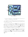
The ATLAS TDAQ network contains a few places where a number of traffic streams are
concentrated to a single destination (a funnel shaped traffic pattern, e.g., the Event Building traffic with data coming from all the ROBs to a single SFI). The performance in such
conditions depends on the amount of buffering inside the switch.
We developed methods to measure the effective buffering capacity for a port on the switch.
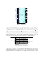
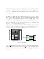
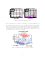
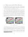
Figure 4.5 shows the buffering capacity for different packet sizes and for 3 different devices,
expressed in number of frames (Figure 4.5(a)) and in kByte (Figure 4.5(b)). The shapes of
the curves can give us insight to the internal memory allocation policy. For example Device
A seems to split and store packets in small (approximately 128 byte) cells, while Device C
uses a fixed-size slot for any packet size. Device B uses a linked-list memory management,
with a total buffering memory of approximately 120 kByte, and a maximum of approximately
105 elements in the list; for small frames (64 to 1100 byte) the limitation is the number of
elements (descriptors) of the list, while for large frames (bigger than 1100 byte) the limitation
is the total memory size.
(a) Measured in frames
(b) Measured in bytes
Figure 4.5: Buffering Capacity
The raw buffer size is not enough to characterize a device. The way the switch deals with
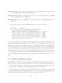
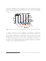
congestion internally is also important. Figure 4.6 shows the loss rate in an ATLAS traffic
scenario for 5 different buffering levels; these measurements are taken for a device that has
user-configurable buffers. The concentration ratio4 was 6 to 1 (six times more servers than
clients). The x-axis represents the intended load to be obtained on the congested ports, and
the loss rate is shown on the y-axis. We observe that for small numbers of available buffers,
packet loss starts to appear at 85% load and this onset increases to 95% when more buffers
4
The concentration ratio represents the number of servers over the number of clients, keeping the terminology from Section 3.1.2.
28