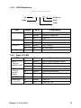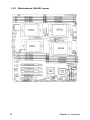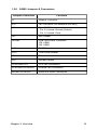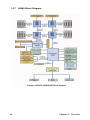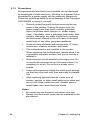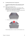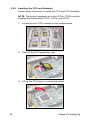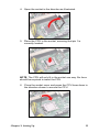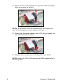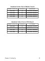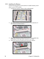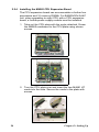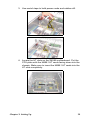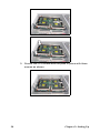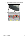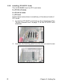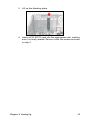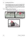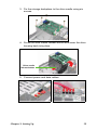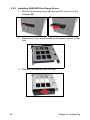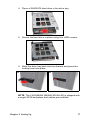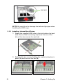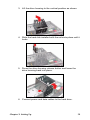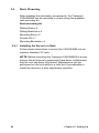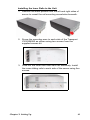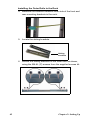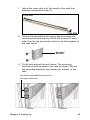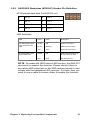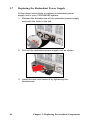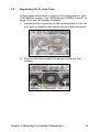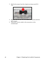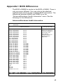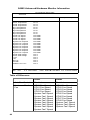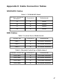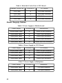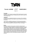
1
Transport VX50 B4985 Series Service Engineer’s Manual Document ID: D1851-101 警告使用者: 這是甲類的資訊產品,在居住的環境中使用時,可能會造成射頻干 擾,在這種情況下,使用者會被要求採取某些適當的對策。 Preface Copyright This publication, including all photographs, illustrations, and software, is protected under international copyright laws, with all rights reserved. Neither this manual, nor any material contained herein, may be reproduced without written consent of the manufacturer. Copyright 2007 Version 1.01 Disclaimer Information contained in this document is furnished by TYAN Computer Corporation and has been reviewed for accuracy and reliability prior to printing. TYAN assumes no liability whatsoever, and disclaims any express or implied warranty, relating to sale and/or use of TYAN products including liability or warranties relating to fitness for a particular purpose or merchantability. TYAN retains the right to make changes to product descriptions and/or specifications at any time, without notice. In no event will TYAN be held liable for any direct or indirect, incidental or consequential damage, loss of use, loss of data or other malady resulting from errors or inaccuracies of information contained in this document. Trademark Recognition All registered and unregistered trademarks and company names contained in this manual are property of their respective owners including, but not limited to the following. TYAN and Transport VX50-B4985, and Thunder n4250QE are trademarks of TYAN Computer Corporation. AMD, Opteron, and combinations thereof are trademarks of Advanced Micro Devices Corporation. Phoenix, PhoenixBIOS are trademarks of Phoenix Technologies. Microsoft Windows is a trademark of Microsoft Corporation. IBM, PC, AT, PS/2 are trademarks of IBM Corporation. Winbond is a trademark of Winbond Electronics Corporation. Portable Document Format (PDF) is a trademark of Adobe Corporation. i Federal Communications Commission Notice for the USA Compliance Information Statement (Declaration of Conformity Procedure) DoC FCC Part 15: This device complies with part 15 of the FCC Rules Operation is subject to the following conditions: 1) This device may not cause harmful interference, and 2) This device must accept any interference received including interference that may cause undesired operation. If this equipment does cause harmful interference to radio or television reception, which can be determined by turning the equipment off and on, the user is encouraged to try one or more of the following measures: • • Reorient or relocate the receiving antenna. • Plug the equipment into an outlet on a circuit different from that of the receiver. Increase the separation between the equipment and the receiver. Consult the dealer on an experienced radio/television technician for help. Notice for Canada This apparatus complies with the Class B limits for radio interference as specified in the Canadian Department of Communications Radio Interference Regulations. (Cet appareil est conforme aux norms de Classe B d’interference radio tel que specifie par le Ministere Canadien des Communications dans les reglements d’ineteference radio.) Notice for Europe (CE Mark) This product is in conformity with the Council Directive 89/336/EEC, 92/31/EEC (EMC). CAUTION: Lithium battery included with this board. Do not puncture, mutilate, or dispose of battery in fire. Danger of explosion if battery is incorrectly replaced. Replace only with the same or equivalent type recommended by manufacturer. Dispose of used battery according to manufacturer instructions and in accordance with your local regulations. ii About this Manual This manual provides you with instructions on installing your Transport VX50-B4985. This manual consists of the following sections: Chapter 1: Provides an Introduction to the VX50-B4985 barebone, packing list, describes the external components, gives a table of key components, and provides block diagrams of the system. Chapter 2: Covers procedures on installing the CPU, memory modules, PCI cards and hard drives. Chapter 3: Covers removal and replacement procedures for pre-installed components. Appendix: Describes the differences between mainboard BIOS and system BIOS. The cable connection tables are also provided for reference of system setup. For information on the mainboard, please refer to the attached mainboard user’s manual. You can find the detailed description about jumper and BIOS settings from the motherboard manual. iii Safety Information Before installing and using the Transport VX50-B4985, take note of the following precautions: iv • • • Read all instructions carefully. • Only use the power source indicated on the marking label. If you are not sure, contact the power company. • The unit uses a three-wire grounded cable, which is supplied with a third pin to ground the unit and prevent electric shock. Do not defeat the purpose of this pin. If your outlet does not support this type of plug, contact an electrician to replace the obsolete outlet. • Do not place anything on the power cord. Place the power cord where it will not be stepped on. • Follow all warnings and cautions in this manual and on the unit case. • Do not push objects in the ventilation slots as they may touch high voltage components and result in shock and damage to the components. • When replacing parts, ensure that you use parts specified by the manufacturer. • When service or repairs have been carried out, perform routine safety checks to verify that the system is operating correctly. • Avoid using the system near water, in direct sunlight, or near a heating device. • Cover the unit when not in use. Do not place the unit on an unstable surface, cart, or stand. Do not block the slots or openings on the unit which are provided for ventilation. Table of Contents Chapter 1: Overview 1.1 About the TYAN Transport VX50-B4985 .................................. 1.2 Product Models ............................................................................ 1.3 Features ........................................................................................ 1.4 Unpacking .................................................................................... 1.4.1 Box Contents.......................................................................... 1.4.2 Accessories ............................................................................ 1.5 About the Product ........................................................................ 1.5.1 System Front View ................................................................ 1.5.2 System Rear View ................................................................. 1.5.3 LED Definitions..................................................................... 1.5.4 Rear I/O LED......................................................................... 1.5.5 Motherboard (S4985) Layout ................................................ 1.5.6 S4985 Jumpers & Connectors................................................ 1.5.7 S4985 Block Diagram............................................................ 1.5.8 CPU Board (M4985) Layout ................................................. 1.5.9 M4985 Jumpers & Connectors .............................................. 1.5.10 M4985 Block Diagram ........................................................ 1.5.11 System Internal View........................................................... 1 1 3 5 5 7 9 9 10 11 11 12 13 14 15 15 16 17 Chapter 2: Setting Up 2.1 Before You Begin ........................................................................ 2.1.1 Work Area.............................................................................. 2.1.2 Tools ...................................................................................... 2.1.3 Precautions............................................................................. 2.2 Installing Motherboard Components............................................ 2.2.1 Removing the Chassis Cover................................................. 2.2.2 Installing the CPU and Heatsink............................................ 2.2.3 Installing the Memory............................................................ 2.2.4 Installing the M4985 CPU Expansion Board ........................ 2.2.5 Installing PCI-E/PCI Cards.................................................... 2.3 Installing Hard Drives .................................................................. 2.3.1 Installing a Storage Backplane .............................................. 2.3.2 Installing SAS/SATA Hot Swap Drives................................ 2.3.3 Installing Internal Hard Drives .............................................. 2.4 Rack Mounting............................................................................. 2.4.1 Installing the Server in a Rack............................................... 2.5 Standalone .................................................................................... 2.6 Fitting the Front Bezel Door ........................................................ 2.6.1 Opening the Front Bezel Door............................................... 19 19 19 20 21 21 22 26 28 32 34 34 36 38 40 40 45 46 47 Chapter 3: Replacing Pre-installed Components v 3.1 Introduction .................................................................................. 3.1.1 Work Area.............................................................................. 3.1.2 Tools ...................................................................................... 3.1.3 Precautions............................................................................. 3.2 Removing the Chassis Cover ....................................................... 3.3 Replacing Motherboard Components .......................................... 3.3.1 Disconnecting All Motherboard Cables ................................ 3.3.2 Replacing the Motherboard ................................................... 3.4 Replacing the DVD-ROM............................................................ 3.5 Replacing the Floppy Disk Drive................................................. 3.6 Replacing the SAS/SATA Backplane .......................................... 3.6.1 SAS/SATA Backplane (M1209-P) Features ......................... 3.6.2 SAS/SATA Backplane (M1209-P) Header Pin Definition.... 3.7 Replacing the Redundant Power Supply...................................... 3.8 Replacing the System Fans .......................................................... vi 49 49 49 50 51 52 52 53 54 56 58 60 61 62 63 Chapter 1: Overview 1.1 About the TYAN Transport VX50-B4985 Congratulations on your purchase of the TYAN TransportTM VX50-B4985, standalone or rack-mountable barebone system. This product supports up to eight AMD® Opteron™ 8000 series 1207-pin processors and 128 GB of registered DRAM, offering exceptional computing power and simultaneous support of 32-bit and 64-bit applications. Hot swap SATA or SAS hard disk drives provide convenient and resilient data storage capacity, and on-board Gigabit Ethernet ports ensure high-speed data communication. 1.2 Product Models Model Supported HDD type & quantity Hot swappable Power Supply B4985V50V4H-4P SAS/SATAII (4) Yes 1140W (2+1 redundant with 1 dummy module) B4985V50V8H-8P SAS/SATAII (8) Yes 1620W (3+1 redundant) B4985V50V4H-4P Chapter 1: Overview B4985V50V8H-8P 1 WARNING: This product is very heavy and should not be lifted by a single person. When installing this product in a rack, we recommend that at least two people lift the server while a third person guides it into place and tightens the fixings. Always use a suitable trolley or cart to transport the device. 2 Chapter 1: Overview 1.3 Features Enclosure Front Panel Features • • • • 5U Convertible Pedestal/rack-mountable chassis Storage: -(3) 5.25” device bays (Pre-installed one standard DVD-ROM) -(1) Slim optical drive bay -(1) Standard FDD (Pre-installed) -(4) Hot swap SAS/SATA HDD bays -(4) Internal HDD bays (upgradable to hot swap bays) Dimensions: -D 26.8 x W 16.7 x H 8.7 inch -D 680 x W 425 x H 220 mm Processors • Supports four AMD® Opteron™ (2.0~2.8GHz) Socket F (1207) 8000 series processors Chipset • • • • NVIDIA nForce Professional 2200 (CK804pro) NVIDIA nForce Professional 2050 (IO4) Winbond W83627HF Super I/O ADT7476 Hardware Monitoring IC • • I/O -(2) USB 2.0 ports LED indicators -Power LED -(2) LAN LED -HDD Active LED -ID LED Switches -Power, Reset, and ID switches Onboard Storage Controller • • • • Four (4) integrated dual port SATA controllers (two from CK804pro and two from IO4) Supports up to eight (8) SATA drives Supports 3.0Gb/s per port, 1.5Gb/s per direction per channel Supports RAID 0, 1, 0+1, 5 Networking • Three (3) Gigabit Ethernet ports -Two (2) Marvell 88E1111 GbE -One (1) Intel 82541PI GbE Video Memory • • • • Motherboard • • Sixteen (16) DDR2 DIMM sockets on S4985 Sixteen (16) DDR2 DIMM sockets on M4985 Supports up to 128GB of Registered, ECC DDR2 667/533/400 four ranks memory module Expansion Slots • • • Two (2) x16 PCI Express slots with x16 signal Two (2) x16 PCI Express slots with x4 signal One (1) 32-bit 33MHz PCI v2.3 slot Back I/O Ports • • • • • One (1) Keyboard & One (1) PS/2 Mouse ports Three (3) RJ45 10/100/1000 Base-T port with activity LED Two (2) USB 2.0 ports One (1) 9-pin UART Serial port One (1) 15-pin VGA port Chapter 1: Overview • • XGI-GX20 PCI graphics controller 16MB DDR memory Resolution Max 1280x1024 TYAN Thunder n4250QE S4985 SSI EEB 3.5 footprint (13 x 16-inch) CPU Board (8 way) • TYAN M4985 (13” x 12”) BIOS • • • • • • Phoenix 8Mbit LPC Flash ROM Serial Console Redirect USB device boot 48-bit LBA support ACPI 2.0 power management support Power management: S0, S1, S4, and S5 Server Management • • • Automatic fan speed control Supports TYAN Server Management (TSM) TYAN SMDC, IPMI v2.0 compliant remote server management kit (Option) 3 Power Supply Regulatory • • • • 1140W to 1620W, optional redundant module 1140W for 4P (2+1 redundant with 1 Dummy module) 1620W for 8P (3+1 redundant) System Cooling • FCC Class B (Declaration of Conformity) CE (Declaration of Conformity) Environment • • Operating: 5ºC~35ºC Non-Operating: -40ºC~70ºC • Three (3)120x120x38mm cooling fans • Four (4) active CPU coolers for S4985 • Four (4) active CPU coolers for M4985 4 Chapter 1: Overview 1.4 Unpacking This section describes the VX50-B4985 package contents and accessories. Open the box carefully and ensure that all components are present and undamaged. 1.4.1 Box Contents Component Description B4985V50V4H-4P: Industry standard 5U chassis, (4) swappable HDD bays B4985V50V8H-8P: Industry standard 5U chassis, (8) swappable HDD bays Tyan Thunder n4250QE S4985G3NR motherboard (pre-installed) M4985 CPU board Standard DVD-ROM drive (pre-installed) Standard FDD drive (pre-installed) Chapter 1: Overview 5 Component Description M1209-P SAS/SATAII backplane (pre-installed) 2+1 redundant with 1 Dummy module / Total 1140W (for B4985V50V4H-4P) 3+1 redundant / Total 1620W (for B4985V50V8H-8P) (3) System cooling fans (pre-installed) 120 x 120 x 38 mm 6 Chapter 1: Overview 1.4.2 Accessories If any items are missing or appear damaged, contact your retailer or browse to TYAN’s Web site for service: http://www.tyan.com. The Web site also provides information on other TYAN products, plus FAQs, compatibility lists, BIOS settings, and more. TYAN Driver CD B4985V50V4H-4P: 4 x CPU Heatsinks with Fans B4985V50V8H-8P: 8 x CPU Heatsinks with Fans B4985V50V4H-4P: Power Cord: Europe x 3pcs US x 3pcs B4985V50V8H-8P: Power Cord: Europe x 4pcs US x 4pcs CD-ROM Flat Cable, 40-pin Barebone Manual & Mainboard Manual Chapter 1: Overview 2 x Serial ATA Power Cables 7 Front Bezel Kit Bezel Door with Keylock Mounting Ears x 2 Keys Screws kit 4 x Chassis Foot Stands HDD Rails Kit Rail Kit Mounting Bracket x 4 Screws Kit 8 Sliding Brackets x 4 Rail assembly Chapter 1: Overview 1.5 About the Product This section contains hardware diagrams and a block diagram of the VX50-B4985 system. 1.5.1 System Front View See the diagram below for details of the front panel indicators and switches. B4985V50V4H-4P Hot Swap HDD bays USB ports Internal HDD bays ID button Reset button 5.25-inch device bays Power button DVD-ROM drive Floppy disk drive LED control panel B4985V50V8H-8P Hot Swap HDD bays USB ports 5.25-inch device bays ID button Chapter 1: Overview Reset button Power button DVD-ROM drive Floppy disk drive LED control panel 9 1.5.2 System Rear View Redundant Power supply 3 x Cooling 2 x USB ports fans Stacked PS/2 mouse and keyboard ports 10 VGA port Serial port 3 x RJ-45 LAN ports Expansion slots AC input Chapter 1: Overview 1.5.3 LED Definitions Power on ID HDD LAN2 LAN1 LED Power LED HDD LED LAN LED ID LED Status On Color Description Green System is turned on On Amber System is turned off Off Off Power off On Amber HDD access Off Off No disk activity Blinking Green LAN is active Off Off No LAN linked On Blue ID select on 1.5.4 Rear I/O LED LED Status RJ45 On Linkage / Blinking Activity (Left) Off Color Description Green 10Mb/100Mb/1000Mb linked Green 10Mb/100Mb/1000Mb activity Off No LAN linked RJ45 Linkage / Activity (Right) On Amber 1000Mb linked/activity On Green 100Mb linked/activity Off Off 10Mb mode or No LAN linked ID LED On Blue ID select on Power supply module On Green Power on Off Off Power off / fail Chapter 1: Overview 11 1.5.5 Motherboard (S4985) Layout 12 Chapter 1: Overview 1.5.6 S4985 Jumpers & Connectors Jumper/Connector Function J1 SMBUS Connector J14 Fan Connector (for barebone use only) J20 Clear CMOS Jumper - Pin 2-3 closed: Normal (Default) - Pin 1-2 closed: Clear J22 NMI Header J30/J95 USB Front Panel Connector J30: USB2 J95: USB3 J101 COM2 Header J115 Front Panel Header JP1 RI Header JP2 Intruder Header CPUFAN0/1/2/3 CPU Fan Connectors SYSFAN0/1/2/3/4/5/6/7 Chassis Fan Connectors SATA0/1/2/3/4/5/6/7 Serial ATA RAID Connectors Chapter 1: Overview 13 1.5.7 S4985 Block Diagram 14 Chapter 1: Overview 1.5.8 CPU Board (M4985) Layout 1.5.9 M4985 Jumpers & Connectors Jumper/Connector Function J1 Power Switch CPUFAN4/5/6/7 CPU Fan Connectors PWR1/2/3/4 Power Connectors SYSFAN8/9 System Fan Connectors Chapter 1: Overview 15 1.5.10 M4985 Block Diagram 16 Chapter 1: Overview 1.5.11 System Internal View 2 1 3 4 5 6 7 8 11 9 12 13 10 1. 2. 3. 4. 5. 6. 7. Memory slots CPU sockets PCI-E x16 slots PCI slot PCI-E x4 slots SAS/SATA cables FDD cable Chapter 1: Overview 8. 9. 10. 11. 12. 13. System fans SAS/SATA backplane Hard disk drive cradles DVD-ROM cable DVD-ROM drive Cradle for 5.25-inch devices 17 18 Chapter 1: Overview Chapter 2: Setting Up 2.1 Before You Begin This chapter explains how to install motherboard components including CPUs, CPU heatsinks, memory modules, CPU expansion board, and hard drives. Instructions on inserting a PCI card are also given. Take note of the precautions mentioned in this section when installing your system. 2.1.1 Work Area Make sure you have a stable, clean working environment. Dust and dirt can get into components and cause malfunctions. Use containers to keep small components separated. Putting all small components in separate containers prevents them from becoming lost. Adequate lighting and proper tools can prevent you from accidentally damaging the internal components. 2.1.2 Tools The following tools will be required to complete the installations described in this chapter. • • A cross head (Phillips) screwdriver A grounding strap and/or an anti static pad Most of the electrical and mechanical connectors in your system can be disconnected using your fingers. It is recommended that you do not use needle-nosed pliers to remove connectors as these can damage the soft metal or plastic parts of the connectors. Chapter 2: Setting Up 19 2.1.3 Precautions Components and electronic circuit boards can be damaged by discharges of static electricity. Working on a system that is connected to a power supply can be extremely dangerous. Follow the guidelines below to avoid damage to the Transport VX50-B4985 or injury to yourself. • Ground yourself properly before removing the top cover of the system. Unplug the power from the power supply and then touch a safely grounded object to release static charge (i.e. power supply case). If available, wear a grounded wrist strap. Alternatively, discharge any static electricity by touching the bare metal chassis of the unit case, or the bare metal body of any other grounded appliance. • Avoid touching motherboard components, IC chips, connectors, memory modules, and leads. • The motherboard is pre-installed in the system. When removing the motherboard, always place it on a grounded anti-static surface until you are ready to reinstall it. • Hold electronic circuit boards by the edges only. Do not touch the components on the board unless it is necessary to do so. Do not flex or stress circuit boards. • Leave all components inside the static-proof packaging that they ship with until they are ready for installation. • After replacing optional devices, make sure all screws, springs, or other small parts are in place and are not left loose inside the case. Metallic parts or metal flakes can cause electrical shorts. Notes: • All connectors are keyed to only attach one way. • Always use the correct screw size as indicated in the procedures. 20 Chapter 2: Setting Up 2.2 Installing Motherboard Components This section describes how to install components on to the motherboard, including CPUs, memory modules and PCI cards. 2.2.1 Removing the Chassis Cover Follow these instructions to remove the Transport VX50B4985 chassis cover. This step is required before any other procedures in this chapter can be undertaken. 1. Press the two purple buttons on the retaining clips and lift them up. The cover slides back slightly. 2. Lift the cover free from the chassis. Follow the steps above in reverse to refit the chassis cover. Chapter 2: Setting Up 21 2.2.2 Installing the CPU and Heatsink Follow these instruction to install the CPU and CPU heatsink. NOTE: The system supports up to four CPUs. CPU0 must be installed first followed by CPU1, CPU2, and CPU3. 1. Locate the four CPU sockets on the motherboard. 2. Take off the CPU protection cap. 3. Lift up the CPU lever to unlock the socket. 22 Chapter 2: Setting Up 4. Open the socket in the direction as illustrated. 5. Place the CPU in the socket, ensuring that pin 1 is correctly located. NOTE: The CPU will only fit in the socket one way. No force should be required to insert the CPU. 6. Close the socket cover and press the CPU lever down in the direction shown to secure the CPU. Chapter 2: Setting Up 23 7. Place the fan and heatsink on top of the CPU and attach with two screws as shown. NOTE: All heatsinks must be installed with fans facing the rear of the chassis to ensure efficient cooling. 8. Attach the fan power cable to the CPU fan pin header on the motherboard as shown. 9. Repeat these steps when installing the other CPUs. NOTE: About the CPU FAN connect with MB ,please refer to following table: 24 Chapter 2: Setting Up Heatsink Coller Fan to Mother board Heatsink Cooler Fan Connects to Motherboard CPU FAN1 CPUFAN0 connector CPU FAN2 SYSFAN5 connector CPU FAN3 CPUFAN2 connector CPU FAN4 SYSFAN4 connector Heatsink Coller Fan to CPU Board Heatsink Cooler Fan Connects to CPU Board CPU FAN5 CPUFAN4 connector CPU FAN6 CPUFAN5 connector CPU FAN7 CPUFAN7 connector CPU FAN8 CPUFAN6 connector Chapter 2: Setting Up 25 2.2.3 Installing the Memory Follow the instructions in this section to install memory modules in your VX50 system. 1. Locate the memory slots on the motherboard. 2. Press the memory slot locking levers in the direction of the arrows as shown below. 3. Align the memory module with the slot. The module has indentations that align with notches in the slots. 4. Insert the memory module into the slot as shown. 26 Chapter 2: Setting Up When inserted properly, the memory slot locking levers lock automatically onto the indentations at the ends of the module. NOTE: Each bank memory of sockets is associated with one CPU. Memory will be recognized only when installed in a socket associated with an installed CPU. Attention When Installing the Memory! Refer to the following table for supported DDR2 populations. CPU DIMM Single (CPU0 only) Dual (CPU 0 and CPU1) Four (CPU0, CPU1, CPU2, and CPU3) CPU0DIMM0 X X X CPU0DIMM1 X X X CPU0DIMM2 X X X X X CPU0DIMM3 X X X X X X CPU1DIMM0 X X X CPU1DIMM1 X X CPU1DIMM2 X X X CPU1DIMM3 X X X X X X CPU2DIMM0 X CPU2DIMM1 CPU2DIMM2 X CPU2DIMM3 X X X CPU3DIMM0 X CPU3DIMM1 X CPU3DIMM2 X X CPU3DIMM3 X X NOTE: 1. X indicates a populated DIMM slot. 2. Always install memory DIMMs in pairs starting from the CPU0_DIMM2 and CPU0_DIMM3. You can choose to install single, dual or four memory modules. Chapter 2: Setting Up 27 2.2.4 Installing the M4985 CPU Expansion Board The CPU expansion board can accommodate a further four processors and 16 memory DIMMs. For B4985V50V4H-4P unit, when upgrading to eight CPU with a CPU expansion board, a further power supply module must be installed. 1. Take out the CPU plate with the mylar attached. Screw the M4985 mainboard to the CPU plate using eleven screws. 2. Turn the CPU plate over and insert the two M4881 HT cards into the slots. Secure the cards to the plate with screws. 28 Chapter 2: Setting Up 3. Use scotch tape to hold power cords and cables still. 4. Locate the HT slots on the S4985 motherboard. Put the CPU plate with the M4881 HT cards facing down into the chassis. Make sure to insert the M4881 HT cards into the HT slots completely. Chapter 2: Setting Up 29 5. Secure the CPU board with the plate in place with three screws as shown. 30 Chapter 2: Setting Up 6. Insert two further countersunk screws to secure the expansion board to the chassis as shown. 7. Connect the four power cables as shown. Chapter 2: Setting Up 31 2.2.5 Installing PCI-E/PCI Cards The VX50-B4985 has five PCI card slots: 2 x PCI-E x16 slots 2 x PCI-E x4 slots 1 x PCI slot Follow these instructions to install any of the above kinds of PCI cards. 1. Locate the PCI-E/PCI card slots on the motherboard. See “System Internal View” on page 17 for the PCI-E/PCI slot locations. 2. Unscrew the blanking plate from the slot you want to use. 32 Chapter 2: Setting Up 3. Lift up the blanking plate. 4. Insert a PCI-E/PCI card into the appropriate slot, making sure it is firmly seated. Secure it with the screw removed in step 2. Chapter 2: Setting Up 33 2.3 Installing Hard Drives The VX50-B4985 supports up to eight hot-swappable SAS or SATA hard drives when two backplanes are installed. When the unit is B4985V50V4H-4P, with four hot-swap bays and one SATA backplane, follow the instructions below to install a further four hot-swap bays and a second SAS or SATA backplane. 2.3.1 Installing a Storage Backplane 1. Release the two screws holding the cradle locking bar in place (A) and remove the bar (B). A B 2. Lift the drive cradle to the vertical position as shown. 34 Chapter 2: Setting Up 3. Fix the storage backplane to the drive cradle using six screws. 4. Press the drive cradle release button and lower the drive housing back into place. Drive cradle release button 5. Connect power and data cables. Chapter 2: Setting Up 35 2.3.2 Installing SAS/SATA Hot Swap Drives 1. Pull out the locking lever (A) and pull the tray out of the chassis (B). A B 2. Remove the four screws holding the plastic spacer in the tray. . 3. Remove the spacer from the tray 36 Chapter 2: Setting Up 4. Place a SAS/SATA hard drive in the drive tray. 5. Secure the hard drive in place using four HDD screws. 6. Slide the drive tray back into the chassis and press the locking lever into place. A B NOTE: The VX50-B4985 (B4985V50V4H-4P) is shipped with a single SATA backplane and cables pre-installed. Chapter 2: Setting Up 37 Light pipe NOTE: Be careful not to damage the delicate light pipe when handling the HDD trays. 2.3.3 Installing Internal Hard Drives 1. Attach the supplied HDD rails to the both sides of a hard disk. Ensure that the locking clip faces the rear of the drive. Use two screws for each rail. 2. Release the two screws holding the cradle locking bar in place (A) and remove the bar (B). A 38 B Chapter 2: Setting Up 3. Lift the drive housing to the vertical position as shown. 4. Slide the hard disk installed with the rails into place until it locks. 5. Press the drive housing release button and lower the drive housing back into place. 6. Connect power and data cables to the hard drive. Chapter 2: Setting Up 39 2.4 Rack Mounting After installing the necessary components, the Transport VX50-B4985 can be mounted in a rack using the supplied rack mounting kit. Rack mounting kit Sliding Rails x 2 Sliding Brackets x 4 Mounting Ears x 2 Screws Kit x 1 Mounting Brackets x 4 2.4.1 Installing the Server in a Rack Follow these instructions to mount the VX50-B4985 into an industry standard 19" rack. NOTE: Before mounting the Transport VX50-B4985 in a rack, ensure that all internal components have been installed and that the unit has been fully tested. Maintenance can be performed on the unit while in a rack but it is preferable to install the device in a fully operational condition. 40 Chapter 2: Setting Up Installing the Inner Rails to the Unit 1. Remove the black panels from the left and right sides of server to reveal the rail mounting screwholes beneath. 2. Screw the mounting ears to each side of the Transport VX50-B4985 as shown using two screws from the supplied screws kit. 3. Draw out the inner rails from each rail assembly. Install the inner sliding rails to each side of the server using five screws. Chapter 2: Setting Up 41 Installing the Outer Rails to the Rack 4. Measure the distance between inner side of the front and rear mounting brackets in the rack. 5. Locate the sliding brackets. Sliding brackets 6. Secure the sliding brackets to the outer rails as shown, using the M4-4L (C) screws from the supplied screws kit. 42 Chapter 2: Setting Up 7. Adjust the outer rails to fit the length of the rack (the distance measured in step 4). 8. Secure the assembled rail sets to the rack using two mounting brackets and four M5L8-H3 screws for each side. Use the top and bottom holes to fix the brackets to the rack frame. Mounting brackets 9. Fit the rails behind the rack frame. The mounting brackets should be against the rails as shown. Secure the mounting brackets from inside, not outside, of the rack. Use the top and bottom holes to fix the rails to the rack Correct Chapter 2: Setting Up Incorrect 43 Rackmounting the Server 10. Lift the server and slide it between the rails mounted in the rack. 11. Bolt the mounting ears to the rack using M5L15-H3 screws to secure the server in place. Notes: 44 • When the rails are extended, they will lock. To shorten the rails again, you will need to operate the release mechanism in each rail. • To avoid injury, it is strongly recommended that two people lift the VX50-B4985 into the place while a third person screws it to the rack. Chapter 2: Setting Up 2.5 Standalone The Transport VX50-B4985 can be used as a standalone device when fitted with the supplied plastic feet. When used as a standalone device, the feet must be fitted to prevent the unit from falling over. The four feet should be attached as follows: 1. Each foot consists of two pieces. Insert the round piece of the foot into the larger foot section. The small plastic tab on the round piece should fit into the curved slot on the other piece. Curved slot Tab fits in curved slot 2. Use a single screw through the center of the round section to fasten the foot assembly to the bottom of the chassis. The plastic tab that protrudes through the curved slot should fit into an indent in the chassis case. When fitted, each foot should rotate about 90°. 3. Fit all four feet in the same way. NOTE: When using as a standalone unit, all four feet should be fitted and extended fully to prevent instability. Chapter 2: Setting Up 45 2.6 Fitting the Front Bezel Door A door is supplied with the Transport VX50-B4985 that can be used when the unit is rack mounted or standalone. Follow these instructions to attach the door. 1. Release the hinge clip from the top of the hinge section on the door 2. Insert the top hinge pin into the hole in the server casing. Align the lower hinge pin with the hole in the casing and lower the door into place. 3. Replace the hinge clip on the top hinge pin. 46 Chapter 2: Setting Up 2.6.1 Opening the Front Bezel Door 1. Insert the front door key (packed in the screws kit in the accessory box) and rotate the key 90 degrees clockwise to unlock the door. 2. Pull the door in the direction of the arrow to open. Chapter 2: Setting Up 47 48 Chapter 2: Setting Up Chapter 3: Replacing Pre-installed Components 3.1 Introduction This chapter explains how to replace all the pre-installed components including the motherboard, DVD-ROM drive, Floppy Disk Drive, SAS/SATA backplane, power supply, and system fans. Take note of the precautions in this section when installing your system. 3.1.1 Work Area Make sure you have a stable, clean working environment. Dust and dirt can get into components and cause malfunctions. Use containers to keep small components separated. Putting all small components in separate containers keeps them from becoming lost. Adequate lighting and proper tools can prevent you from accidentally damaging the internal components. 3.1.2 Tools The procedures that follow require only a few tools, including the following: • • A cross head (Phillips) screwdriver A grounding strap or an anti-static pad Most of the electrical and mechanical connections can be disconnected using your fingers. It is recommended that you do not use needle-nosed pliers to remove connectors as these can damage the soft metal or plastic parts of the connectors. Chapter 3: Replacing Pre-installed Components 49 3.1.3 Precautions Components and electronic circuit boards can be damaged by static electricity. Working on a system that is connected to a power supply can be extremely dangerous. Follow the guidelines below to avoid damage to the Transport VX50B4985 or injury to yourself. • Ground yourself properly before removing the top cover of the system. Unplug the power from your computer power supply and then touch a safely grounded object to release static charge (i.e. power supply case). If available, wear a grounded wrist strap. Alternatively, discharge any static electricity by touching the bare metal chassis of the unit case, or the bare metal body of any other grounded appliance. • Avoid touching motherboard components, IC chips, connectors, memory modules, and leads. • The motherboard is pre-installed in the system. When removing the motherboard, always place it on a grounded anti-static surface until you are ready to reinstall it. • Hold electronic circuit boards by the edges only. Do not touch the components on the board unless it is necessary to do so. Do not flex or stress circuit boards. • Leave all components inside the static-proof packaging that they ship with until they are ready for installation. • After replacing optional devices, make sure all screws, springs, or other small parts are in place and are not left loose inside the case. Metallic parts or metal flakes can cause electrical shorts. Notes: 50 • All connectors are keyed to only attach one way. • Always use the correct screw size as indicated in the procedures. Chapter 3: Replacing Pre-installed Components 3.2 Removing the Chassis Cover Follow these instructions to remove the Transport VX50B4985 chassis cover. This step is required before any other procedures in this chapter can be undertaken. To remove the rear cover and expose motherboard components: 1. Press the two purple buttons on the retaining clips and lift them up. The cover slides back slightly. 2. Lift the cover free from the chassis. Follow the steps above in reverse to refit the chassis cover. Chapter 3: Replacing Pre-installed Components 51 3.3 Replacing Motherboard Components Follow these instructions to remove motherboard components and replace the motherboard. 3.3.1 Disconnecting All Motherboard Cables Before replacing the motherboard or certain components, remove cables connected to the motherboard. Follow these instructions to remove all motherboard cabling. 1. Disconnect all the power cables. Main power EPS 12V power IDE power 12V power 2. Disconnect the DVD-ROM drive cable, SAS/SATA hard drive cables, USB cable, and front panel cables. SAS/SATA cables FDD cable DVD-ROM cable USB cable Front panel cables 52 Chapter 3: Replacing Pre-installed Components 3. Disconnect the fan cables. 3.3.2 Replacing the Motherboard After removing all of those cables, follow these instructions to remove the motherboard from the chassis. 1. Remove the heat sinks and processors if installed. 2. Remove the nine screws that secure the motherboard to the chassis. 3. Carefully lift the motherboard from the chassis. NOTE: The motherboard is too large to lift straight out. Lift the front edge of the motherboard up to an angle of about 45º. Then slide the motherboard out, front end first. Chapter 3: Replacing Pre-installed Components 53 3.4 Replacing the DVD-ROM Follow these instructions to replace the DVD-ROM. 1. Remove the power and data cables from the rear of the DVD-ROM drive. 2. Remove the two thumbscrews that secures the DVDROM drive to the chassis. 3. Slide the DVD-ROM drive out of the chassis in the direction of the arrow shown. 54 Chapter 3: Replacing Pre-installed Components 4. Install a new DVD-ROM drive in the drive bay and secure with two thumbscrews. 5. Replace the power and data cables. Chapter 3: Replacing Pre-installed Components 55 3.5 Replacing the Floppy Disk Drive Follow these instructions to replace the FDD in your VX50B4985 system. 1. Loosen the two screws that secure the lower cover to the chassis of the VX50-B4985. Slide the cover back and remove it to expose the service port for the floppy disk drive. 2. Remove the power and data cables from the floppy disk drive. 3. Loosen the two thumbscrews that secures the floppy disk drive in place. 56 Chapter 3: Replacing Pre-installed Components 4. Slide the floppy disk drive out of the chassis. 5. Slide the new unit into place, secure with the two thumbscrews and replace the power and data cables. Chapter 3: Replacing Pre-installed Components 57 3.6 Replacing the SAS/SATA Backplane Follow these instructions to replace the SAS/SATA backplane in your VX50-B4985 system. 1. Remove all the SATA hot swap HDD trays from the VX50-B4985. 2. Release the two screws holding the cradle locking bar in place (A) and remove the bar (B). A B 3. Disconnect all cables from the SATA backplane. 58 Chapter 3: Replacing Pre-installed Components 4. Lift the drive cradle to the vertical position as shown. 5. Remove the six screws to release the backplane. 6. Lift the backplane from the chassis. Drive cradle release button 7. Secure a new backplane in place with six screws. 8. Press the drive cradle release button and lower the drive cradle back into place. (See the drive cradle release button indicated in the step 6.) 9. Reconnect the power and data cables. Chapter 3: Replacing Pre-installed Components 59 3.6.1 SAS/SATA Backplane (M1209-P) Features Front View Hot Swapped HDD Fail LED Hot Swapped HDD Power/Access LED J1 SAS 29 PIN Connector J2 SAS 29 PIN Connector J3 SAS 29 PIN Connector J4 SAS 29 PIN Connector Rear View JP3 2x4 pin header J13 Big 4P J14 Big 4P J5 SATA II 7 pin primary J6 SATA II 7 pin primary J7 SATA II 7 pin primary J8 SATA II 7 pin primary J12 SATA II 7 pin secondary J11 SATA II 7 pin secondary J10 SATA II 7 pin secondary J9 SATA II 7 pin secondary 60 Chapter 3: Replacing Pre-installed Components 3.6.2 SAS/SATA Backplane (M1209-P) Header Pin Definition JP3 External Hard disk Fail LED Pin out 1 AF+1 2 AF-1 3 BF+1 4 BF-1 5 CF+1 6 CF-1 7 DF+1 8 DF-1 LED Definition LED Color State Description Hot Swappable HDD Tray Power/Access LED Green ON Power connected Green Blinking HDD access activity OFF OFF Power disconnected Amber ON SAS HDD fail (Reserved for SAS add-on card) OFF OFF No failure found Hot Swappable HDD SAS Failed LED NOTE: To enable the HDD failure LED function, the SAS PCI card need to support this function. Please check if there is any failure LED output pin on the SAS card and check if it can comply with the backplane LED input pin. If it does, then you need to use a cable to connect them to enable this function. Chapter 3: Replacing Pre-installed Components 61 3.7 Replacing the Redundant Power Supply Follow these instructions to replace a redundant power supply unit in your VX50-B4985 system. 1. Release the thumbscrew of the redundant power supply and push the latch to the left. 2. Pull out the redundant power supply unit as shown. 3. Insert the new unit secure it by tightening the thumbscrew. 62 Chapter 3: Replacing Pre-installed Components 3.8 Replacing the System Fans Follow these instructions to replace the cooling fans in your VX50-B4985 system. See “Motherboard (S4985) Layout” on page 12 for the fan header locations. 1. Locate the fan connector on the motherboard for the fan you want to replace and unplug the fan cable as shown. 2. Remove the four screws that secure the fan to the chassis. Chapter 3: Replacing Pre-installed Components 63 3. Pull the fan away from the chassis as shown and lift it free. 4. Replace the new fan into the chassis and secure with the four screws. 5. Reconnect the fan cable to the connector on the motherboard. 64 Chapter 3: Replacing Pre-installed Components Appendix I: BIOS Differences The BIOS of B4985 is similar to the BIOS of S4985. There is only one menu different. You may refer to the attached motherboard manual for the complete BIOS information. The differences between B4985 and S4985 is on the “Advanced/Hardware Health Information” menu. See the following for the differences. Advanced/Hardware Health Information PhoenixBIOS Setup Utility Advanced Hardware Monitor: CPU0 Temperature CPU1 Temperature CPU2 Temperature CPU3 Temperature CPU4 Temperature CPU5 Temperature CPU6 Temperature CPU7 Temperature sys1 Temperature sys2 Temperature sys3 Temperature sys4 Temperature sys5 Temperature CPU1 Fan Speed CPU2 Fan Speed CPU3 Fan Speed CPU4 Fan Speed CPU5 Fan Speed CPU6 Fan Speed CPU7 Fan Speed CPU8 Fan Speed System Fan 1 Speed System Fan 2 Speed System Fan 3 Speed CPU0 VDD voltage CPU1 VDD voltage CPU2 VDD voltage CPU3 VDD voltage CPU4 VDD voltage CPU5 VDD voltage CPU6 VDD voltage CPU7 VDD voltage +12V +5V HT1.2V 3.3VSB CK804 Vcore 1.5V F1 Esc Help Exit xxx ºC xxx ºC xxx ºC xxx ºC xxx ºC xxx ºC xxx ºC xxx ºC xxx ºC xxx ºC xxx ºC xxx ºC xxx ºC xxxx RPM xxxx RPM xxxx RPM xxxx RPM xxxx RPM xxxx RPM xxxx RPM xxxx RPM xxxx RPM xxxx RPM xxxx RPM xxxx V xxxx V xxxx V xxxx V xxxx V xxxx V xxxx V xxxx V xxxx V xxxx V xxxx V xxxx V xxxx V Select Item Select Menu Item Specific Help All items on this menu cannot be modified in user mode. If any items require changes, please consult your system Supervisor. -/+ Change Values F9 Setup Defaults Enter Select X Sub-Menu F10 Save and Exit 65 S4985 Advanced/Hardware Monitor Information PhoenixBIOS Setup Utility Advanced Hardware Monitor CPU0 Temperature CPU1 Temperature CPU2 Temperature CPU3 Temperature Sys1 Temperature Sys2 Temperature Sys3 Temperature Sys4 Temperature Sys5 Temperature CPU0 Fan Speed CPU1 Fan Speed CPU2 Fan Speed CPU3 Fan Speed System Fan 0 Speed System Fan 1 Speed System Fan 2 Speed System Fan 3 Speed System Fan 4 Speed System Fan 5 Speed System Fan 6 Speed System Fan 7 Speed CPU0 VDD voltage CPU1 VDD voltage +12V +5V HT1.2V 3.3VSB CK804 Vcore 1.5V F1 Esc Help Exit Item Specific Help xxx ºC xxx ºC xxx ºC xxx ºC xxx ºC xxx ºC xxx ºC xxx ºC xxx ºC xxxx RPM xxxx RPM xxxx RPM xxxx RPM xxxx RPM xxxx RPM xxxx RPM xxxx RPM xxxx RPM xxxx RPM xxxx RPM xxxx RPM xxxx V xxxx V xxxx V xxxx V xxxx V xxxx V xxxx V Select Item Select Menu -/+ Change Values F9 Setup Defaults Enter Select X Sub-Menu F10 Previous Values Table of Differences 66 S4985 B4985 Auto Fan Control Disabled Enabled Hardware Monitor Fan CPU0 Fan Speed CPU1 Fan Speed CPU2 Fan Speed CPU3 Fan Speed System Fan0 Speed System Fan1 Speed System Fan2 Speed System Fan3 Speed System Fan4 Speed System Fan5 Speed System Fan6 Speed System Fan7 Speed CPU1 Fan Speed CPU2 Fan Speed CPU3 Fan Speed CPU4 Fan Speed CPU5 Fan Speed CPU6 Fan Speed CPU7 Fan Speed CPU8 Fan Speed System Fan1 Speed System Fan2 Speed System Fan3 Speed Appendix II: Cable Connection Tables SAS/SATA Cables Table 1: VX50-B4985 Model M1209-P SAS/SATA Backplane Connects to Motherboard J5 SATA1 J6 SATA0 J7 SATA3 J8 SATA2 FAN Cables Table 2: System Fan to Motherboard System Fan Connects to Motherboard FAN 1 SYSFAN1 connector FAN 2 SYSFAN0 connector FAN 3 SYSFAN2 connector Table 3: Heatsink Cooler Fan to Motherboard Heatsink Cooler Fan Connects to Motherboard CPU FAN1 CPUFAN0 connector CPU FAN2 SYSFAN5 connector CPU FAN3 CPUFAN2 connector CPU FAN4 SYSFAN4 connector 67 Table 4: Heatsink Cooler Fan to CPU Board Heatsink Cooler Fan Connects to CPU Board CPU FAN5 CPUFAN4 connector CPU FAN6 CPUFAN5 connector CPU FAN7 CPUFAN7 connector CPU FAN8 CPUFAN6 connector Power Supply Cables Table 5: Power Supply to Motherboard Power Supply Connects to Motherboard 24-pin power cable PWR0 24-pin connector 8-pin power cable PWR1 8-pin connector 8-pin power cable PWR2 8-pin connector 4-pin power cable PWR3 4-pin connector 4-pin power cable PWR4 4-pin IDE connector Table 6: Power Supply to CPU Board Power Supply Connects to CPU Board 24-pin power cable PWR1 24-pin connector 8-pin power cable PWR2 8-pin connector 8-pin power cable PWR3 8-pin connector 4-pin power cable PWR4 4-pin connector Table 7: Power Supply to Backplane Power Supply 68 Connects to Backplane 4-pin power cable J13 4-pin connector 4-pin power cable J14 4-pin connector Table 8: Power Supply to DVD-ROM Power Supply 4-pin power cable Connects to DVD-ROM 4-pin connector Other Cables Table 9: DVD-ROM Related Cables Motherboard IDE connector DVD-ROM 4-pin power connector DVD-ROM Table 10: FDD Related Cables Motherboard FDD connector FDD drive 4-pin power cable FDD drive 69 Appendix III: Installing the SMDC Card The following provides you with the information on installing M3291 SMDC card into any PCI slot in your VX50-B4985 system. 1. Secure M3291 on a PCI bracket as shown. 2. Connect the following cables to M3291 as shown. a. 2x25 pin SMDC cable to M3291 J1 connector. b. 2x5 pin serial cable to M3291 COM port (J2). 3. Unscrew the blanking plate from the slot as shown. Lift up the blanking plate. 70 4. Connect the other end of SMDC cable and serial cable to the SMDC connector and COM2 header (J101) on the motherboard. 5. Place the SMDC card in the PCI slot as shown. 6. Secure the PCI bracket with the screw you removed from the blanking plate. 71 Cable Connection Table SMDC Card (M3291) 72 Connects to Motherboard J1 connector SMDC connector J2 COM port J101 COM2 header Technical Support If a problem arises with your system, you should first turn to your dealer for direct support. Your system has most likely been configured or designed by them and they should have the best idea of what hardware and software your system contains. Hence, they should be of the most assistance for you. Furthermore, if you purchased your system from a dealer near you, take the system to them directly to have it serviced instead of attempting to do so yourself (which can have expensive consequences). If these options are not available for you then TYAN Computer Corporation can help.Besides designing innovative and quality products for over a decade, TYAN has continuously offered customers service beyond their expectations. TYAN's website (www.tyan.com) provides easy-to-access resources such as in-depth Linux Online Support sections with downloadable Linux drivers and comprehensive compatibility reports for chassis, memory and much more. With all these convenient resources just a few keystrokes away, users can easily find the latest software and operating system components to keep their systems running as powerful and productive as possible. TYAN also ranks high for its commitment to fast and friendly customer support through email. By offering plenty of options for users, TYAN serves multiple market segments with the industry's most competitive services to support them. "TYAN's tech support is some of the most impressive we've seen, with great response time and exceptional organization in general" - Anandtech.com Please feel free to contact us directly for this service at [email protected] Help Resources: 1. See the beep codes section of this manual. 73 2. See the TYAN website for FAQ’s, bulletins, driver updates, and other information: http://www.tyan.com 3. Contact your dealer for help BEFORE calling TYAN. 4. Check the TYAN user group: alt.comp.periphs.mainboard.TYAN Returning Merchandise for Service During the warranty period, contact your distributor or system vendor FIRST for any product problems. This warranty only covers normal customer use and does not cover damages incurred during shipping or failure due to the alteration, misuse, abuse, or improper maintenance of products. NOTE: A receipt or copy of your invoice marked with the date of purchase is required before any warranty service can be rendered. You may obtain service by calling the manufacturer for a Return Merchandise Authorization (RMA) number. The RMA number should be prominently displayed on the outside of the shipping carton and the package should be mailed prepaid. TYAN will pay to have the board shipped back to you. TYAN Transport VX50-B4985 Series User’s Manual V1.01 Document ID: D1851-101 74 75