1
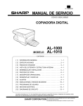
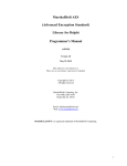
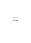
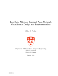
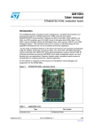
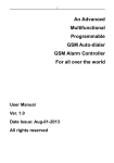
Microprocessor Systems Final Project
A Wireless Game of Bulls and Cows
Presented to Mr. Jean-Samuel Chénard on December 3rd, 2009 by
Mathieu Perreault (260158758)
Logan Smyth (260179735)
Simon Foucher (260223197)
Alexandru Susma (260235940)
Contents
Executive Summary .......................................................................................................................................................................... 3
Overview ...................................................................................................................................................................................... 3
Features ....................................................................................................................................................................................... 3
Team Members ............................................................................................................................................................................ 3
Images .......................................................................................................................................................................................... 3
Hardware Overview .......................................................................................................................................................................... 4
Software Architecture....................................................................................................................................................................... 6
PS2 Keyboard and Hex Display via SPI slave ................................................................................................................................ 6
Wireless Communication ............................................................................................................................................................. 6
Display Control ............................................................................................................................................................................. 7
4-bit mode ............................................................................................................................................................................... 7
Initialization Procedure ........................................................................................................................................................... 7
Sending Data ........................................................................................................................................................................... 8
Helper functions ...................................................................................................................................................................... 8
User Interface .............................................................................................................................................................................. 8
Initialization............................................................................................................................................................................. 8
Option 1: Hosting Player User Interface.................................................................................................................................. 9
Option 2: Joining Player User Interface ................................................................................................................................... 9
Common Stream: Game User Interface .................................................................................................................................. 9
Game Logic, Reliable Wireless Communication and User Interface ............................................................................................ 9
Initialization........................................................................................................................................................................... 10
Host Stream .......................................................................................................................................................................... 10
Join Stream............................................................................................................................................................................ 11
Common Game Stream and wireless protocol...................................................................................................................... 11
Flash Memory ............................................................................................................................................................................ 13
Problems or Unresolved Issues ....................................................................................................................................................... 14
Flash Problems ........................................................................................................................................................................... 14
McGumps Boards & CPLD Unit .................................................................................................................................................. 14
Interrupts ................................................................................................................................................................................... 14
Wireless ..................................................................................................................................................................................... 14
Conclusion ...................................................................................................................................................................................... 15
Bibliography .................................................................................................................................................................................... 16
Appendix A – State Machine Diagram ............................................................................................................................................ 17
Executive Summary
Overview
This document presents the design and implementation of a wireless platform capable of playing the
cows and bulls game. The platform was built using the McGumps board, which incorporates a TI MSP430
microprocessor, an Altera MAX CPLD chip, 2 UART interfaces and RS-232 and Parallel ports. The platform
also includes the eZ430-RF2500T low-power wireless module (commonly called the CC2500). The overall
product is a self-contained unit that can wirelessly synchronize itself with another device, designed
under the same wireless protocol, and enable the user to wirelessly play the cows and bulls game.
Features
•
•
•
•
•
External LCD Character Display (2 lines of 24 characters)
Integration of any PS/2-compatible keyboard via a second SPI slave
Reliable wireless communications
High-level finite-state machine software architecture
Debug interface via an RS-232 connector and LED display on the board
Team Members
•
•
•
•
Mathieu Perreault – Team Leader, Display integration
Logan Smyth – Software Architect, PS/2 keyboard and wireless communication integration
Simon Foucher –Game development, Reliable Wireless Protocol Implementation
Alexandru Susma – Software Development, Memory and Game Development
Images
Figure 1 – (a) A user playing C&B using a PS/2 keyboard
(b)Naked board showing peripherals and PS/2 connection
Hardware Overview
Figure 2 - Wiring diagram for the platform
Table 1 – Wirewrap Table for the whole platform
eZ430-RF2500T
PIN
17
16
15
18
2
1
13
NAME
SIMO
CLK
SOMI
STE
VCC
GND
GDO0
2x24 LCD Character Display
PIN
NAME
11
DB4
12
DB5
13
DB6
14
DB7
5
RW
4
RS
6
E
1
GND
2
VDD
Variable Resistor
PIN
to
to
to
NAME
VDD
VEE
Variable Resistor
to
Vo
PS/2 Keyboard
PIN
1
3
4
5
to
NAME
Data
Ground
+5V
Clock
McGumps
PIN
H1[04]
H1[10]
H1[08]
H1[06]
H1[01]
H1[37]
H2[26]
NAME
OUTA0
OUTA3
OUTA2
OUTA1
3.3V
GND
P1.1
McGumps
PIN
H2[05]
H2[06]
H2[07]
H2[08]
H2[09]
H2[10]
H2[11]
H2[03]
H2[01]
NAME
P6.0
P6.1
P6.2
P6.3
P6.4
P6.5
P6.6
GND
5V
McGumps
PIN
1
3
2x24 LCD Char. Display
3
McGumps
PIN
H1[34]
H1[38]
H1[40]
H1[36]
NAME
5V
GND
Vo
NAME
OUTD5
GND
5V
OUTD6
Software Architecture
PS2 Keyboard and Hex Display via SPI slave
Access to the PS2 keyboard and onboard seven-segment displays is accomplished using SPI. By making
use of our preexisting SPI communication code and implementing an SPI slave in VHDL, we can very
easily transfer data bidirectionally between the MSP430 and the CPLD.
We have offloaded much of the key press processing from the CPU onto the CPLD, allowing us to reduce
the size of the interrupt routine. We began by implementing the SPI slave, which is a simple shift
register, and then proceeded to develop the processing of the keyboard.
PS2 Keyboards return values of between 1 and 3 bytes depending on the key pressed, and each code
relates to a specific key and action, such as press or release (Savard, 2007). We chose to use the VHDL to
process these key codes, and then use an SPI transaction of 3 bytes to retrieve the values and convert
them into ASCII inside the CPU. While this processing could have been done on the CPLD as well, the
total size of the logic must be considered, since at the time we had also not implemented the hex
display yet. When a key is pressed, the keyboard transmits the data serially with a start, stop and parity
bit. When the last byte is received, the keyboard sends an interrupt to the CPU, will then read the scan
codes and return an ASCII value.
Wireless Communication
The wireless is accessed via two methods, wireless_packet_transmit(packet* p) and
wireless_packet_receive(packet* p). Transmit will write the contents of the packet into the TX FIFO one
byte at a time and then set the cc2500 to TX mode. Receive simply reads a packet from a queue in
memory and will return false if no packets are in the queue.
The system uses the receive interrupt to pull data in from the CC2500, which gives up several benefits.
Primarily it allows up to buffer more packets, which means we are less likely to drop values and
wherefore increases reliability. Similarly, it reduces the time spent polling for packets because we simply
check the queue instead of needing to do an SPI transaction. Another important benefit of this is that it
allows us to abstract away several features such as heartbeat processing, which therefore reduces the
complexity of the game loop. If we were to extend the protocol, this abstraction also would allow us to
implement a reliable transmission protocol such as GoBackN transparently to the user.
We chose to store packet data in a single struct called packet, which contains a union for the body data.
A union allows us to store several different data types in the same memory space, while at the same
time keeping the values type-safe. This means that we do not need to cast back and forth between types
and are protected by the standard compile time type checks. This also means that at transmission time,
we simply have to cast our packet to a char* and iterate based on the length and read it back in the
same fashion to restore an exact copy of the struct at the other end.
Display Control
This part will describe the implementation of a display controller using the MSP430. Specifically, the
display controller was used to control the LUMEX “LCD-S401C40TF-1” 2x24 LCD Character Display used
in this platform. The reference material was gathered from difference sources, the main of which is the
datasheet of the LCD controller made by Samsung, the S6A0069 (Electronics, 2000). As shown in the
Wiring Diagram in a previous section, the particular LCD connected to the MSP430 in this platform is
connected to 9 pins of the H2 header of the McGumps board. Specifically, the four pins that are used to
transmit data and the three pins that are used to control the type of data sent are connected to Port 6
of the MSP430. Furthermore, two more pins are connected to Ground (GND), and one to the +5V pin.
The contrast of the LCD is controlled by a variable resistor. For more details about the connection, see
Table 1, above. To implement some of the following procedures, some code was taken from the web
(Nighsoft, 2009).
4-bit mode
It was decided that the implementation of the display controller in this platform would use the 4-bit
mode. The main reason behind this choice was that Port 6 on the MSP 430 has only 8 pins whereas the
8-bit transaction mode of the Samsung controller would have required 8 data pins and 3 control pins,
which exceeds the number available on Port 6. Instead of using part of another MSP430 port and
because it required little more complexity, it was decided to use 4-bit mode.
Initialization Procedure
Functions: lcd_init(void)
Following the previously cited datasheet for the display controller,
the initialization procedure, shown in Table 2, was performed on
Port 6 of the MSP430. Our implementation would set the signals
as appropriate for a transaction and pulse the “E” signal up and
down, signaling the Samsung controller that valid data was on the
line. Our implementation would also wait the required amount of
time between different transactions, as specified by Figure 1. The
different variables possible to configure the LCD were
parameterized as follows:
DL = 0 : 4-bit mode
N = 1 : 2-line mode
F = 1 : Display ON
D = 1 : Display ON
C = 0 : Underline cursor OFF
B = 0: Cursor blink ON
SH = 0: Entire Shift OFF
ID = 1: Increment ON
Figure 3 - 4-bit Initialization Sequence
Sending Data
Functions: send_data(char c)
To send 8-bit data to the display (in this case, printable characters), we set the 4 data lines to the most
significant bits of our data first and pulse the “E” signal. Then, the 4 less significant bits are loaded on
the appropriate lines are the “E” signal is probed again.
Helper functions
Building on the function to send data explained above, we have implemented a set of functions to
control what is printed on the screen. The following is a brief explanation of the more important ones.
void lcd_putchar(char c);
This function takes as input a character and puts it on the screen at the current cursor location.
void lcd_goto(char p);
This function takes a position (0 to 47) and moves the cursor to that position on the LCD. It takes care of
wrapping around to prevent writing off-screen.
void lcd_clearscreen(void);
This function clears the screen.
char lcd_printf(char* format, ...);
This function, adapted from work by Logan Smyth (Soft. Architect), emulates the standard printf
function found in stdlib. It parses the different argument types normally found in printf (e.g. %d, %x, %s,
%c, etc.) and prints on the LCD the proper rendering of the string.
void lcd_clearline(int line);
This function clears whatever line (1 or 2) it is passed as argument.
User Interface
Initialization
The main output device of our Cows and Bulls wireless platform is the 2x24 LCD Character Display. The
following user interface description will assume output on this display device.
Upon boot-up of the system, users are greeted with a Welcome message and are asked to press Enter to
get to start the game. They are then brought to the
“Enter your name” screen, which they complete with
the standard input device in this system, the PS/2
keyboard. Once the users enter their names and press
the Enter key, they can press H or J, depending if they want to (H)ost or (J)oin a game, respectively. Any
other key press will generate an error message. Based on whether the users are hosting or joining a
game, the user interface will differ from Option 1 to Option 2, below:
Option 1: Hosting Player User Interface
Once it is determined that the users want to host a game, the display informs the users that a
connection is currently being set-up and sending reconnaissance beacons. When a join request comes in
from a person trying to connect to the host, the users are shown a prompt on whether they want to
accept (Y) or refuse (N) the connection from “user2,” where user2 is the name of the person wishing to
join as they entered in the Initialization of the game. The User Interface then becomes common to both
hosting and joining users as detailed in Game User Interface, below.
Option 2: Joining Player User Interface
Once it is determined that the users want to join a game, the display informs the users of an available
game and sends a Join Request in the background to the host. Then, the User Interface will become
common to both hosting and joining users as detailed in Game User Interface, below.
Common Stream: Game User Interface
Once users have entered the Game user interface, they will first be prompted for their own secret
combination. As they type, the combination will be shown on the screen. They cannot enter the same
digit twice in a combination (e.g “1123” is
illegal). Once they press enter, they are brought
the guess input screen. From there, they can
type a guess for the other person’s secret
number, and hit enter to send that guess. The
Cows and Bulls count of that guess will be
displayed a few seconds later when the result is
received from the other party. Also, while in the
guess input screen, users can press the TAB key
repeatedly to go back and see the results of all the previous guesses they have made. Those results will
be updated in the background as they are sent by the other player. To go back to the Guess Input
screen, users should continue pressing TAB until the desired screen comes back up again (emulating a
page shuffling or tab architecture). Once one of the users win the game by finding the correct
combination, the correct message (You win, you lose) is displayed on each of the users’ device and
shortly after, a Game Over message appears, prompting the users to press Enter to return to the
host/join menu.
Game Logic, Reliable Wireless Communication and User Interface
The game was designed using a FSM, and both players use a very similar path in the state machine. The
FSM starts at a common place then splits up into 2 streams while synchronizing players: one for hosting
and one for joining. After the synchronization of both board, both player rejoin the ‘common’ game
stream until the game is over. Once the game is over, the FSM will stall in its final state until a key is
pressed, afterwards will move back to the initialization state to enable the player to restart a game. The
game rules were taken from the web (Wikipedia, 2009).
The entire game flow is managed in the file ‘game.c’ with frequent function calls to driver files. Typically,
when the FSM changes state, it sets a flag called ‘firstTime’ to TRUE. The next time the while loop
evaluates the game state, if this flag is set, the code will execute some state initialization script then set
the flag to false. This could have been implemented by the use of function calls or intermediary states,
but it was done in this manner in order to visually localize the code to facilitate understanding and
debugging.
Initialization
Functions: playgame(void)
States: PRINT_INIT, HOST_OR_JOIN
PRINT_INIT
This is the initial state when the board is turned on and the game activated. The first time the state is
visited, old guesses from previous games are removed (not deleted, but the pointers are set back to
initial position), the heartbeats are turned off, the player name buffer is formatted and the player is
prompted to press enter to begin then type his name.
When the function returns to this state, it will freeze in a getchar function until a key is presses. The
ASCII key code will be recorded in a temporary buffer called ‘keybuf’ then interpreted. If the key pressed
was a writable ASCII, it will be recorded in the player name string which will then get printed. If the
player presses backspace, the last letter in player name string gets deleted, and if the player pressed
‘enter’ the game will display the recorded name then proceed.
We make the user of a keybuf buffer throughout the game such that we can filter between command
and data keys. We can then interpret the content of the buffer and then either execute the command or
record the data, based on the content of the buffer.
HOST_OR_JOIN
Simple state; prompts the user to hit ‘h’ to host or ‘j’ to join. If the user presses h/H, the game enters the
host stream by changing to state ‘SEND_HOST_BEACON‘. If the user presses j/J, the game enters the join
stream by going to state ‘LISTEN_FOR_BEACON’. Any other key pressed will print an error message.
Host Stream
SEND_HOST_BEACON
Upon entering this state, a beacon packet is built in the packet struct ‘beacon’ then sent a first time, and
the game time in seconds is recorded in the variable ‘last_time’. Afterwards (and every time the game
enters this state in the main while loop) the variable ‘INTERVAL’ records the timer ticks (range 0-32767).
Then, if the game seconds have increased by ‘GAME_HOST_BEACON_INTERVAL’, the game records the
new seconds count in ‘last_time’, waits ‘INTERVAL’ ticks then sends another beacon packet and prints a
message on the screen with ‘last_time’ as a reference number such that the user can observe the
packets being sent out. With this code, packets are sent at pseudo-random intervals: they will be sent
out every ‘GAME_HOST_BEACON_INTERVAL’ seconds (fixed as a #define) + ‘INTERVAL’ timer ticks
(which should change from one read to the other due to asynchronous interrupts). We can then manage
the beacon interval while maintaining non-constant send times.
Once the beacon is sent, if any, all the packets in the packet queue will be read. If one of those packets
is of type ‘R’, the name of the responder is printed on the screen and the game moves to the next state.
Otherwise, the packet is discarded.
DO_YOU_ACCEPT
In this state, the host just received a join request from a player and is prompted if he accepts the game
or not. The game freezes in a getchar function and key presses are recorded in a buffer. If the user
presses y/Y, heartbeats are enabled (which will signal the joiner that his request got accepted), the
other player’s address is recorded and the game enters the common game stream. If the user presses
n/N, the game goes back to SEND_HOST_BEACON and keeps broadcasting. If the user presses ‘escape’,
the user goes back to HOST_OR_JOIN.
Join Stream
LISTEN_FOR_BEACON
When entering this state, first we look for a timeout condition. We compare the variable last_time
(which recorded the game seconds when the player pressed ‘j’ in HOST_OR_JOIN state) with the current
game seconds and a timeout threshold. If the game time has passed the threshold, we assume that
there are no games to be found; an error message is printed and the game goes back to HOST_OR_JOIN
state.
Afterwards, we probe the packet queue to see if we received a beacon type packet. If so, we extract the
other player’s name and display it on the screen. The source address of the received beacon is recorded
and set as the packet target address and the state changes to ACCEPT_BEACON.
ACCEPT_BEACON
In this state, the board has found a game it could potentially join. The code sets up a beacon with this
player’s name and sends it out. The game time in seconds is recorded and the state is changed to
WAIT_HOST_HB.
WAIT_HOST_HB
Since a join request has been sent, if the other player accepts it he will enter that game mode and will
start sending out heart beats. In this state, the joiner listens for a heart beat coming from the host he
has contacted. There are 3 outcomes from this state. First, if a heart beet has not been found before a
timeout, print an error message and go back to state HOSR_OR_JOIN. Second outcome, a heart beet has
been received from the same address where the beacon was picked up, start the game by proceeding to
state INIT_BOARD. In the third outcome, after waiting one second, if a heart beet has not yet been
picked up but the join sequence has not timed out yet, the state is set to ACCEPT_BEACON, where
another beacon will be sent out and then the game will come back here.
Common Game Stream and wireless protocol
Weather the player chooses to host or join a game, as soon as synchronization is completed, both
players enter this stream the same way and play their game with the same code.
INIT_BOARD
This state is for the players to enter their secret numbers. First the buffers are reset, the heart Beats
enabled (not done yet for the joiner) and the game pauses in a getchar function until the user presses a
key which is stored in keybuf. Once a key is pressed, it is interpreted. If an invalid key is detected, a
warning is printed and the key is ignored. The game goes back to the getchar function and waits for
another key. If a valid digit from 0-9 is pressed, if it is not already present in the number the player is
choosing, it is recorded and an up-to-date version of the player’s number entry is printed on the screen.
As per the game’s requirements, the number is a character string, not an integer array. If the user
presses backspace, the last entry of the player’s number is erased from memory and his number is reprinted. Finally, if the user presses ‘enter’, if he has previously entered 4 digits in his number, the game
proceeds to the GRAB_INPUT state, otherwise, the key press is ignored.
GRAB_INPUT
When this state is first entered, they key buffer is deleted since it still contains the player’s number.
Afterwards, if there are packets in the packet queue, they are interpreted by calling the function
interpret_response. There are 2 types of packets this function is meant to interpret: guesses and
responses to guesses since heartbeats and system packets are dealt with internally and do not appear in
the packet queue. If we received a guess, we count the cows and bulls and send back an answer. If the
other player found 4 bulls, the game prints ‘you lose’ on this player’s screen and goes to state
GAME_OVER. If we received a Y type packet, we record the cows and bulls in the previous guess buffer
and print on the screen the result received. Here also, if this player guesses 4 bulls, ‘you win’ is printed
and the game goes to GAME_OVER state.
Once all the packets in the packet queue have been interpreted, the code checks to see if we lost
contact via heartbeats. If so, an error message is printed and the game goes back to PRINT_INIT state.
Then the game stalls into a modified getchar function called getchartimeout. Since we are not running
an OS to manage this multi-function environment, we need to free the CPU to check the packet queue
every so often, so this function is like a getchat, except that it times out every 1/3 seconds, letting the
program move forward. If during this period a key was pressed, it is recorded in keybuf. If the function
times out, a timeout code is returned and recorded in keybuf. Afterwards, if keybuf has the timeout
code, the function breaks, such that it goes back to checking the packet queue. Otherwise, we know that
a key has been pressed and we interpret it.
If the user pressed enter, if he had previously entered a 4 character guess, the game moves to
SEND_DATA. If the user presses backspace, the last character of the user’s guess is deleted. If the user
presses ‘tab’, his previous guesses get displayed sequentially (if any) on the screen. After all the guesses
have been displayed, one more tab will bring back the guess screen. The old guesses are recorded in an
array, and the game can record up to 30 guesses, after which, the buffer will start to overwrite the
oldest guesses. Finally, if the user pressed a valid number, if it is not already present in his guess, it is
recorded.
SEND_DATA
This state is entered when a guess is to be sent out. To manage wireless coherence, we use 2 variables:
wait answer, which is a counter that decides how many guess packets are going to be sent out until we
give up if no answer is received, and gotAnswer, which will be set to true by the interpret_response
function of an answer to our guess got received. It would have been easier to simply have the guess
number returned with the guess result, but this was not part of the protocol outlined guidelines, so here
is how we worked around it.
This first thing done in this state is to interpret any packets in the buffer and interpret them. It might
seem counter intuitive to look for a response before sending out a guess, but it is done this way such
that the packet buffer gets emptied and any guess the other would have send is interpreted before we
send out this guess. By doing so, we reduce the chances that the reply to this guess generates an
overflow. Afterwards, if we haven’t received an answer yet, we send out the guess and decrement the
waitAnswer variable. Once this variable reaches zero, we assume that there is too much interference at
the moment, print an error message and go back to GRAB_INPUT state. If we did received an answer to
our guess, the flag gotAnswer got set to true in the interpret packet function, and the answer already
got recorded in the oldGuessesResult buffer (but the pointer never got incremented, such that if we
receive many answers to the same packet, they will be written to memory but without the pointer
increment, will not affect the game). The guess send gets recorded in the oldGuesses buffer, and the
oldGuesses pointer gets incremented such that the reception of any other responses to this guess will
be written in an unused memory location. Once the response has been processes, the game goes back
to the GRAB_INPUT state.
GAME_OVER
Simple state reached once the game is over. Buffers are reset, and when the user presses a key, the
game goes back to HOST_OR_JOIN to enable a next game.
Flash Memory
For this project, the flash module of the MSP430 is used to store the values of all the configuration
registers of the CC2500 Radio Frequency Chip. Once all the values are known, they are written to
memory and read every time we reboot the system.
To implement flash memory access, both reading and writing, the information found in the User Manual
proved to be very helpful. Understanding how the module works the flash timing generator was set and
functions to perform writes and reads from memory were implemented. The starting address at which it
was decided to store the registers is 0x1000 from the Flash Information Memory. Setting the registers of
the flash controller we were able to perform erases, reads and writes. To write the values to memory a
loop reading through all the CC2500 register was used. After every value was read it was written as a
single byte to memory. For reading the same approach was taken.
Problems or Unresolved Issues
Flash Problems
Problems were encountered when writing the code for the flash memory access. Knowing that flash
memory erase state is all 1s and realizing that before performing a write one needs to erase the
memory, we included the erase code in a loop whose goal was to write multiple bytes to flash. The
result was pretty strange since only the last byte was written. Checking again the way flash memory is
divided it was realized that the smallest part one can erase at a time is a 512 bytes segment. Removing
the erase from the loop made the function write all the bytes properly to flash. The module was tested
on its own and worked in all cases, however because it was not until the last moment that we integrated
the code in the complete system, we ran into some trouble. Putting the code together with the rest of
the system seemed to create some interrupts to overlap while reading and writing through the SPI from
the CC2500 chip. Due to the lack of time it never got fixed. Another design mistake made while
implementing flash was the choice of address. Analyzing the memory segmentation we realized that
flash memory actually starts at 0x1000. Reading the manual we found out that code and information
can be located in both the Flash Main Memory and Flash Information Memory. Even though in our case
it did not seem to interfere with the code, a good thing to do before choosing 0x1000 would have been
to see if there was anything there to begin with.
McGumps Boards & CPLD Unit
During the entire semester, the CPLD chips were performing unreliably. Due to the socket design, the
pins were sometimes not properly connected which made our code to act weird. To fix the problem we
had to lightly poke the CPLD to make sure contacts were made. Early on, it was not clear what the
problem was and the team spent a lot of time debugging the code, while the actual problem was within
the board itself. Towards the end the poking did not work anymore so both boards had to eventually be
replaced.
Interrupts
While working on the project we ran into a lot of problems caused by overlapping interrupts. Since our
whole system is interrupt based we had different functions performed at different times triggered by
interrupts. When interrupts would occur at the same time and basically interrupt each other, the
program would freeze.
Wireless
Given the hardware we had available and the amount of interference present in the lab, a lot of time
was spent on making the two boards communicate reliably. The biggest problem encountered while
working on the basic send receive functions were the CRC Errors, which were caused most likely by the
overlapping channels and interference from the McGill Wireless access points as well as from other
teams working on the project.
Conclusion
The Wireless Cows and Bulls platform was an interesting project to implement. Our team appreciated
the fact that the final project built upon modules developed in previous labs, therefore alleviating the
tasks of developing all the drivers at once. The wireless protocol was simple enough to implement and
the CC2500 was abstracting away a lot of complicated signal processing. The SPI interface was a good
choice because of its versatility and ease of configuration. However, our team has found that the CPLD
chip had limited resources. Some time was lost in trying to optimize the VHDL code such that it would be
compiled and mapped in the available macrocells. Also, the poor quality of the CPLD sockets used made
us waste a significant amount of time trying to debug the code, only to find out days later that the issue
was actually with the socket connections. A word can be said about the Quartus software, which is
numerous versions behind the latest one available (5.0 vs 9.1), especially considering that the latest
version is installed in the Digital Systems Design lab in Trottier. Also, Rowley has released version 2.0 of
its compiler, which bring better performance and more functionality. Overall, our team was satisfied
with the results of this project. The actual competition format made us try to raise the bar as high as
possible and I hope we made it to a certain extent.
Bibliography
Electronics, S. (2000, June). S6A0069 Datasheet.
Nighsoft. (2009, Jan. 11). Sparkfun Forums. Retrieved 11 04, 2009, from Sparkfun:
http://forum.sparkfun.com/viewtopic.php?t=13656
Savard, J. (2007). Scan Codes Demystified. Retrieved 12 2, 2009, from John Savard's Homepage:
http://www.quadibloc.com/comp/scan.htm
Wikipedia. (2009). Bulls and Cows. Retrieved 12 2, 2009, from Wikipedia:
http://en.wikipedia.org/wiki/Bulls_and_cows
And all the datasheets and specification documents we were provided with in the context of the class.
Appendix A – State Machine Diagram