1
Extending m
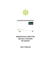
MobilePartners.com
MobilePartners
MPW2100-23
Remotely Managed
3G repeater
User’s Manual
Preface
This User Manual provides installation, configuration, operation and maintenance guidance of the
repeater. Specifications are also provided at the end of this User Manual in order to help users better
understand the repeater. Please read this user’s manual thoroughly and follow the instructions outlined
in this manual to ensure a long life span and a trouble-free repeater unit.
Warranty
Lightning protection must be done for all outdoor antennas. Damage to power modules, as a result of
lightning is not covered by the warranty.
Switching on the AC or DC power prior to connection of antenna cables is considered as an incorrect
installation process and therefore faults arising thereafter are also not covered under the warranty.
This entire manual should be read and understood before operating or maintaining the repeater system.
We assume no liability for customer's failure to comply with the precautions mentioned. This warranty
will not cover such failures to comply.
Safety Information
Do not operate equipment in an explosive environment. Appropriate AC or DC power needs to be supplied to the repeater. To avoid power supply spark, please perform the grounding connection of the
equipment.
In order to avoid equipment damage or human injury by lightning, static electricity and other phenomenon of leakage electricity, we suggest all products must do the electric-discharge of the electrical
grounding in setup process. Incorrect power settings can damage the repeater and may cause electrical
related injury to the user.
Acknowledgment
Thank you for purchasing the MPW2100-23A repeater. Strict quality control system procedures are
implemented to ensure you a high quality product; with numerous cellular operators acknowledging the
product to be a high performance, low interference, transparent and simple to operate and maintain.
This document is written to the customer service personnel, who install, configure and commission the
repeater system in a cellular network.
Contents
1INTRODUCTION
1.1 MPW2100-23 Series Repeaters
1.2 General Installation Layout
1.3 Advantages
2
INSTALLATION
2.1 Isolation
2.1.1Self-Oscillation Resistance
2.1.2The Isolation Value
2.2 Precautions and Preparation
2.3 Donor Antenna Installation
2.4 Server antenna Installation
2.5 Repeater Installation
2.5.1Installing the Repeater
3COMMISSIONING
3.1 Downlink Output Power
3.2 Repeater Configuration
3.2.1Start-up the Repeater
3.2.2Repeater Settings
4
MAINTENANCE
4.1 Alarms
4.2 Troubleshooting
1. Introduction
1.1 MPW2100-23 Series Repeaters
The MPW2100-23 Series Repeater is compact in size and light in weight. Hence, the installation of the
MPW2100-23 Series Repeater is easy, simply just plug and play. With the control panel in front of the
repeater, the repeater status can be known during installation.
1.2 General Installation Layout
Figure 1 Profile
For indoor application, a typical installation layout of the Broad Band Repeater is shown in Figure 1. The
MP17P 17dBi panel antenna is used as the donor antenna, and is connected to the repeater. Omni and
panel antennas are being used as the server antennas.
The donor antenna is placed outside of the building, while the repeater is placed inside the building to
extend radio coverage to the dead zones.
1.3 Advantages
Fast & easy Installation
The installation of a repeater is easy and simple. With its plug and play design, installation simplicity, and
operational user friendliness, these features appeal greatly to many operators for the purpose of indoor
coverage or for temporary coverage during network optimization.
MPW2100-23A has a smart function which can be activated via the front panel. This smart function can
prevent UL interference and self-oscillation caused by insufficient isolation between donor and server
antennas, and also setup parameters and keep optimal condition automatically; the only thing for users is
just activating this function by front panel.
Note. The users can’t adjust by manual setting when smart function is active.
Auto Level Control
The 25dB ALC is used to maintain steady output power even when the donor source signal fluctuates.
Also when the ALC is activated, the ISOLATION LED indicator would be lighted in orange, which means
the Isolation may not be enough. It also prevents UL interference and self-oscillation from insufficient
isolation between donor and server antennas.
Antenna isolation testing
MPW2100-23 series product also has an antenna isolation detection function. Equipment installation
completed boot automatically after the onset detection transceiver antenna isolation, if transceiver
antenna isolation can not meet the installation requirements, the device will automatically reduce the
gain to guarantee the equipment in normal working, not self-excitation vibration, guarantee not to interference protection of base station, repeater itself. At the same time alarm exhibit of lanterns bright red
light alarm.
Device LED gain display panel will display device is reduced after the equipment current gain state, which
has the advantages of convenient construction, but also to protect the base station equipment, and does
not generate interference.
2. Installation
2.1 Isolation
Isolation is an important concept for the repeater system, and it is one of the factors that affect the location of the donor antenna and the location of the server antenna. In the repeater system, the isolation
must be enough, which means the donor antenna cannot be installed too close to the repeater. But what
is isolation? The isolation is the propagation loss between the donor antenna and the server antenna
which needs to be at least 15dB higher than the gain value of the repeater. Non-compliance to this criterion would result in poor signal quality or poor signal strength in the coverage area and the amplifier of
the repeater may also be damaged.
Isolation => Repeater Gain + 15 dB
2.1.1 Self-Oscillation Resistance
Self-oscillation is a phenomenon that would occur when the isolation for the repeater system is not
enough. In other words, insufficient isolation between donor and server antennas would result in selfoscillation. Which means part of the signal that is being amplified by the repeater radiates back towards
the donor antenna and got picked up by the donor antenna and went through the repeater amplification
process again. Severe oscillation issue would result in poor signal quality and at times it can even damage
the repeater amplifiers. Self-oscillation will deteriorate the signals inside the coverage area and interfere
towards the BTS.
2.1.2 The Isolation Value
The precise estimation of the isolation value can be obtained via a physical test measurement. This test
measurement is done at the actual environment where the donor antenna and the server antenna are
installed for a repeater system. The test measurement procedures are
1 Connect the signal generator to the donor antenna and transmit a signal with a frequency. Choose
frequency 1995MHz to do the test. In simple words, choose the idle frequency of the system to do the
test) of certain power level from the signal generator.
2 Connect the spectrum analyzer to the server antenna and scan for the known frequency (The frequency used by the signal generator). Mark the received power level on the spectrum analyzer.
3 Subtract the power level received at the spectrum analyzer from the output power (OP) level of the
signal generator to obtain the isolation value.
Isolation (dB) = Output Power from the signal generator – Received Power on the spectrum analyzer
Transmit a strong Output Power from the Signal generator is recommended (excess of 20dBm) for easy
recognition and detection by the spectrum analyzer.
2.2 Precautions and Preparation
1 Ensure the power applied to the repeater is within its working range. A separate circuit breaker is
recommended.
2 Ensure the donor antenna is installed at the location where signal from the donor BTS (Node B) is
good enough.
3 Ensure there’s sufficient isolation between the donor and server antenna.
4 The repeater is designed for indoor application. Ensure the location of the repeater is dry and
ventilated.
5 Ensure there are adequate resources to handle the weight of the repeater. 6. Some electronic parts
contain carcinogenic constituents, please handle the repeater with care, and discard the in a safe place
if necessary.
2.3 Donor Antenna Installation
The location of the donor antenna strongly influences the performance/characteristics of the RSCP and
Ec/No of the intended coverage area.
The donor antenna is usually installed outside of the building, pointing towards the donor BTS (NodeB)
for best reception of the receiving signal. When choosing the location for the donor antenna, there are 3
criteria need to be met:
1 The RSCP of the donor signal is suggested to be in the range of -60dBm to -70dBm.
2 (Ec/No)AS_CPICH > -7dB; AS_CPICH is the Pilot Channel in Active Set (Serving Cell)
3 (Ec/No)AS_CPICH – (Ec/No)MS_CPICH > 6dB
The donor antenna should be installed at least 3 meters above the ground but not higher than 7th floor
of any building. If the donor antenna is located at a high floor, it would be difficult to obtain a dominant
BTS signal from nearby BTS.
A lightning rod is necessary when the donor antenna is located at a relative high position. A 50 ohm lightning arrestor could be connected between repeater and donor antenna for better protection.
Waterproofing of the antenna installation is also important, and it can be done with the following
process:
1 Use the donor antenna cable to form a half loop at the point of entry into the house so that rain water
would drop off instead of flowing inside along the cable, and also form a half loop before the antenna
cable connects to the repeater as the waterproof measure.
2 Secure the cable entry point. Seal the donor antenna’s connector and repeater’s connector with a
waterproof sealant.
2.4 Server antenna Installation
Find the right spot to install the server antenna so the required coverage can be fully covered by the
repeater is one of the most important concepts that need to be considered.
However, the following three points should be considered while installing the server antenna.
1 Do not install the server antennas near metal or obstacles that may influence its coverage
performance.
2 Do not install server antennas near other electronic equipment (minimum 1 meter) and not near fluorescent lamps or tubes (minimum 2 meters).
2 It is suggested to install the antennas at least 2m above the floor for the best coverage.
3 The server antenna should not be installed to close to the donor antenna to avoid issues with
isolation.
2.5 Repeater Installation
2.5.1 Installing the Repeater
A lightening arrestor needs to be connected to the repeater’s BTS port when the donor antenna is
installed in a high position. Grounding is essential for the arrestor to work.
Plug the power cable to the repeater first before plugging in the power cable to the mains socket. Use
the power cable that comes with the package.
3. Commissioning
This chapter outlines the process to optimize the performance of the repeater. The gain setting, isolation
concept, and downlink output power.
3.1 Downlink Output Power
The downlink output power of the repeater mainly depends on the input signal power and the repeater
gain. The gain is the amplifying indicator for both uplink and downlink in the repeater, and it can be
adjusted. Hence, the output power of the repeater can be estimated.
Signal Input Power + DL Gain = DL Output Power
For any given input signal power, its corresponding output is increased by the gain of the repeater. To
ensure the maximum output power, the following condition should be met.
DL Gain = Min [(DL Output Power – Input Power), Max. DL Gain]
If the input signal amplified by the gain set exceeds the rated set output limit, the ALC (Automatic Level
Control) will be triggered. The ALC ensures that the maximum output power of repeater is maintained at
a certain point and does not overdrive the repeaters amplification circuit.
3.2 Repeater Configuration
The MPW2100-23Aseries repeaters are designed with plug and play ability. The configuration for these
repeaters is not necessary, simply just switch the Smart function on, and the repeater would auto adjust
its gains according to the environment condition.
Use the OMT software to set operator prior to installation.
3.2.1 Start-up the Repeater
Note: It is suggested that only when isolation is 15dB higher than repeater’s gain then the repeater can
be switched on.
Make sure power supply cable is connected to the repeater properly, and the voltage is within repeater’s
voltage working range: 110/220V ± 20%
Plug the power cord into the proper socket. Once the repeater is on, it requires several seconds for
initialization.
When Repeater is close to the BTS, hence there is a high input power at the donor antenna. Even with the
smart ability of the auto gain adjustment, it is still recommended to add an RF attenuator at repeater’s
BTS port to avoid interference to the BTS.
3.2.2 Repeater Settings
After switching on the repeater, the repeater would automatically adjust both uplink and downlink gain
value based on the repeater installation environment if the smart function is turned on. The repeater can
also be adjusted manually via the front control panel.
Figure 5 Front panel of the repeater
Over all staus
and Smart mode
on/off, Silent
Mode on/off
Uplink and
Downink Gain
settings and
alarms
Buttons Function Explanations
Buttons
Function
Explanations
Smart mode key
Press this key, the repeater can convert between Smart
mode and normal mode. Press up to two times to switch.
Make sure that the Smart LED changes.
Slilent Mode key
Press this key to activate or deactivate Silent mode. Silent
mode on will activate the uplink sleep mode that will save
energy and most of all save the load on the operators BTS
Gain attenuation key
Intelligent mode off, Press this key, the uplink and downlink gain will reduce. The greatest reduction is 31dB. Each
press of the key is 1 dB.
When Intelligent mode turned on this key is invalid.
Gain increase key
Intelligent mode off, Press this key, uplink and downlink
gain will increase. Each press of the key is 1 dB.
When Intelligent mode turned on this key is invalid.
Store key
Press Store to store all changes in settings
Select Uplink/Downlink key
Press Select to change from Uplink to Downlink Settings.
The UL and DL LEDs will indicate selected Uplink/Downlink
Battery key
Enable/Disable backup battery power.
Used to shut down OMT module and internal 3G modem
while repetaer is running on battry backup power.
LED
Function
Explanations
Power LED
DC-ON, Power LED is Green, Indicates that the power
supply is normal.
Run LED
Green: Monitoring module is on and working
Off: Monitoring module is off
Alarm1 LED
Green: No problems
Red: Automated Gain Control is out of range
Alarm2 an Alarm3 LEDs are not used on MPW2100-23
Module LED
Green: OMT module has a working connection to the
repeteater.
Red: OMT module has problem communicating with
repeater
Modem LED
Green: Modem is working ok.
Smart LED
Green: Smart Mode is on.
Off: Smart Mode is odd
Silent LED
Green: Silent Mode on
Off: Silent Mode off
System LED
Green: Indicates the active band. System1 is 3G on 2100
MHz.
MPW2100-23 does not support other bands so System2
and System3 is not use
Manual gain mode
When not using Smart Mode, you can manually lower your repeaters gain by adding attenation. Every
press on the - or + button will manually decrease (or increase) the total gain by 1 dB. You can manually
decrease gain from 70/75 down to 36/41dB.
While pressing + or - the LED display will be blinking to show you your settings. Use Store key to store
settings.
This can be very useful if you have very strong input signal or if you need to keep internal repeater signals from leaking out from your house/appartment/office or if your operator is experiencing interfer
An Example of Setting (To set attenuation for the uplink)
Step 1: Press SELECT till the indicator stops at uplink.
Step 2: Press STORE and LED monitor starts blinking.
Step 3: Press“+”, “-”to an intended gain value.
Step 4: Press STORE to set the value and the LED stop blinking and showing the gain value at the
moment, the process is done.
4.Maintenance
4.1 Status, Alarms possible Solutions
Local alarms
Alarm LED
Cause
Solutions
Alarm1
Green
Automatic Gain Control
working normal
Normal
Alarm1 Red Automatic Gain Control out
of limit
1. Increase the distance between donor and server
antenna
2. Decrease gain
3. Check antenna directions
Remote alarms using OMT software
Alarm
Cause
Solutions
DL AGC
alarm
1. High input level at the
BTS port of the repeater,
AGC is active and more than
30dB attenuation has been
applied.
1. Increase the separation distance of the donor and service antenna.
2. Decrease the gain by adjusting the manual attenuation
accordingly to clear the alarm.
2. An isolation condition may
also have occurred.
PA Failure
The power of PA is not
stable
1. Check whether the input DC power is stable. If the DC is
not stable, an UPS with square wave is recommended.
2. Restart this repeater. If input DC power is correct and
alarm still exists, return the unit to place of purchase for
repair.
Power
Module
Alarm
PLL Unlock
1. Input AC power is not
stable.
2. Repeater’s power supply
module has been damaged
The PLL circuit cannot lock
onto the programmed
frequencies. The operating
frequencies of repeater
may have been accidentally shifted from the OMT
software.
1. Check whether the input AC power is stable, it should be
within 110/220V ± 20%. If the AC is not stable, an UPS with
square wave is recommended.
2. In the condition input AC power is correct and alarm still
exists, return the unit to place of purchase for repair.
1. Execute the Default Setting through OMS. Refer to OMT
User’s Manual for more detail.
2. If the alarm cannot be solved, it means repeater has
been damaged. Please return the unit to place of purchase
for repair.
4.2 Troblueshooting
This table offers the fundamental guidelines for troubleshooting advice for the MPW2100-23A. Before
sending the repeater back to the factory for service, please check the troubleshooting measures listed
below first.
Status
Possible reason
Solution
No LED is lit
No AC power.
Check if the power cord is
plugged into the repeater and
the socket properly.
No amplification after repeater
installed.
1. Your phones is showing LTE or
GSM signals.
1. If you have a LTE/4G phone it
would probably lock to LTE/4G
signal (even if that signal is very
low) when you are not making
phonecalls. This is normal.
2. Donor Signal is poor
3. Bad service antenna/cables
4. Wrong operator band?
Test by locking your phone in 3G
only mode or test by making a
phone call and see if it switches
to 3G.
2. Ensure signal strength and
signal quality at the donor
antenna is good enough. Check
signal meter on the repeatre for
input signal
3. Check cables and connector to
the internal service antenna.
4. Check the selected operator
band by the software.
Coverage decreased after certain 1. Donor signal strength
period.
decreased.
1. Check the signal strength at
donor antenna. Re-locate the
Donor Antenna to solve problem.
2. The quality of feeder cable
system decreased due to oxidiza- 2. Check the VSWR of the feeder
tion especially in harsh condicable system to find out the
tions, or cable damage by mice or faulty point and then replace it
insects.
3. Reconsider the position of
3. Change of indoor structure or antennas and the layout of
furniture.
cables if such change occurs.
Bad Ec/No Quality inside the
coverage area
1. Self-oscillation occurred
severely. ISOLATION LED may be
lighted in red.
1. Check the isolation between
donor and server antenna.
1. Self-oscillation occurred.
1. Check the isolation between
donor and server antenna. Turn
on the Intelligent Mode
2. Adjust the donor antenna
2. Poor Ec/No Quality from donor direction or relocate the donor
source
antenna.
Call drop frequently
2. Signal handover frequently.
3. Donor BTS problem
2. Make sure the RSCP for primary BCCH > than 1st neighbor
BCCH by a minimum of 6dB
3. Consult the operator’s RF
engineer.