1
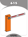
615BPR AUTOMATIC SYSTEM
ENGLISH
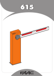
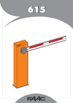
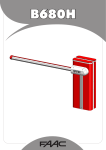
The 615BPR automatic system consists of an aluminium
beam with reflex reflectors, and a steel upright subjected
to cataphoresis treatment and painted with polyester paint.
The upright houses the hydraulic operator and the electronic
control equipment.
TABLE 1
Technical specifications of “615BPR barrier”
BARRIER MODEL
615BPR STD
615BPR RAP
5
2,5
Max. opening time (sec)
5,7
2,9
The operator, which moves the beam, consists of a hydraulic
power pack and a double-acting cylinder.
Angle speed (rad/sec)
0.28
0,54
Pump flow-rate (l/min)
1.5
3
The system is supplied with an adjustable torque limitation
system. It also includes a device stopping the beam in any
position, and a handy manual release command for use in
case of power cuts or faults.
Max. torque (Nm)
400
300
Beam max. length (m)
Rectangular/Rectangular
Skirt Articulated
Types of beam
Use frequency (at 20°C)
The beam and the relevant balancing spring must be ordered
by referring to the sales price list.
Max.consecutive cycles (at 20°C)
40%
220
340
230V~ (+6 -10 %) 50Hz
Power supply
The 615BPR automatic system was designed and built
for controlling vehicle access. Do not use for any other
purpose.
50%
220
Absorbed power (W)
FAAC HP OIL
Type of oil
0,9
Oil quantity (Kg)
1 DESCRIPTION AND TECHNICAL SPECIFICATIONS
Winding thermal protection
120° C
Torque adjustment system
standard by-pass valves
-40 ÷ +55 °C
Ambient temperature
Hood protective treatment
cataphoresis
Polyester RAL 2004
Hood paint
IP 44
Protection class
34
Weight (Kg)
270 x 1015 x 140
Upright overall dimensions LxHxD(mm)
Electric motor technical specifications
1400
RPM
2800
220
Capacity (W)
1
Absorbed current (A)
230V~ (+6 -10 %) 50Hz
Power supply
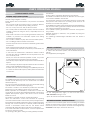
1.1 MAXIMUM USE CURVE
The curve makes it possible to establish maximum work time (T)
according to use frequency (F).
E.g. The 615BPR automatic system can operate non-stop at a use
frequency of 50%.
To ensure efficient operation, operate in the work range below
the curve.
Important: The curve is obtained at a temperature of 20°C. Exposure
to the direct sunlight can reduce use frequency down to 20%.
Calculation of use frequency
The percentage of effective work time (opening + closing) compared
to cycle total time (opening + closing + pause times).
Calculation formula:
%F =
햲
햳
햴
햵
햶
햷
햸
햹
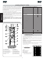
foundation plate
barrier upright
electronic equipment
emergency release
torque adjustment screws
double-acting piston
stroke limit screw
beam
햺
햻
햽
햾
햿
헀
헁
헂
equaliser
oil filling plug
breather screw
balancing spring
spring adjustment tie-rod
hydraulic pump unit
stroke limit sensors
stroke limit magnets
OT + CT
Ta + Tc + Tp + Ti
X 100
where:
Ot =opening time
Ct =closing time
Pt =pause time
It = interval time between a
full cycle and the next.
fig.1
10
3