1
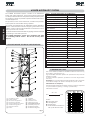
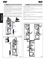
2 ELECTRICAL DEVICES (standard system)
RX
햲
햳
햴
햵
햶
fig.2
615BPR actuator
Photocells
Key push-button
Flashing lamp
Receiver
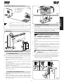
fig.4
1) To lay cables, use adequate rigid and/or flexible
tubes.
2) Always separate connection cables of low voltage
accessories from 230V~ supply cables. To prevent any
interference whatever, use separate sheaths.
fig.5
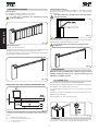
4.3 MECHANICAL INSTALLATION
1) Remove the cover, unscrewing the screws securing it
to the upright.
2) Using the four nuts and washers supplied, secure the upright
to the foundation plate (fig.5 ref.A). Remember that the
upright door should normally face the building.
3) Decide whether the installation is right-hand (Fig. 7/A)
or left-hand (Fig. 7/B) in connection with the references
below.
The 615BPR automated system is always
supplied in the right-hand version - for left-hand
installation, see chapter 4.5.
Make sure that the piston rod fitted on the rocker arm
is fully extended (corresponding to the beam's vertical
position).
4) Remove and store the breather screw as shown in fig.9
ref.A.
5) Assemble the flange (fig.6-ref.1) centrally, on the shaft
(Fig.6-rif 2), checking if the holes securing it to the beam
are on the closing side.(Fig.6-ref 3)
Position the washer (Fig.6-Ref.4) and carry out the tightening
operations of the screw and relevant grower (Fig. 6ref. 5).
Tightening requires considerable force as the
flange is secured on the hexagonal shaft by
interference.
6) Vertically fit the beam (Fig.6-ref 6) on the flange (Fig.6-ref
1) and secure it with the supplied screws (Fig.6 ref.7).
7) Fit the protective cover (Fig.6 ref.8) on the flange (Fig.6-ref
6) and secure it with the supplied screws (fig.6 ref.1).
Install and adjust the balancing spring.
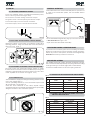
3 DIMENSIONS
Values are in mm.
fig.3
4 INSTALLING THE AUTOMATIC SYSTEM
4.1 PRELIMINARY CHECKS
To ensure safety and an efficiently operating automatic
system, make sure the following conditions are observed:
•
•
•
•
•
When moving, the beam must not, on any account,
meet any obstacles or power cables.
The soil must permit sufficient stability for the foundation
plinth.
There must be no pipes or electric cables in the plinth
excavation area.
If the barrier body is exposed to passing vehicles, if
possible make use of adequate means of protection
against accidental impact.
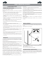
Check if an efficient earth socket is available for
connection to the upright. Use the supplied nuts and
washer (fig. 5 ref.B).
4.2 MASONRY FOR FOUNDATION PLATE
1) Make a foundation plinth as shown in fig.4 (referred to
clayey soil)
2) Wall the foundation plate as shown in fig.4, supplying
one or more sheaths for routing electric cables. Using a
spirit level, check if the plate is perfectly level. Wait for
the cement to set.
fig.6
4
ENGLISH
TX