1
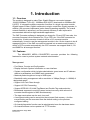
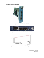
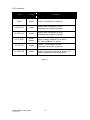
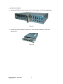
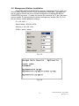
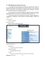
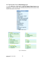
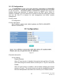
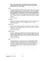
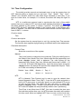
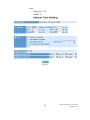
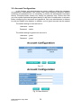
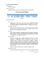
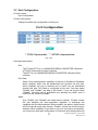
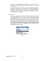
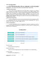
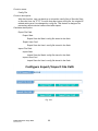
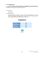
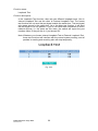
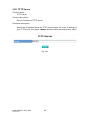
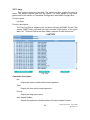
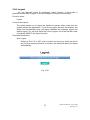
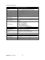
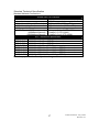
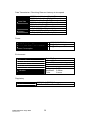
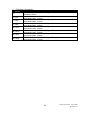
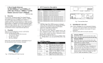
1
User's Manual
Managed Media Converter
Release 1.0
i
Table of Contents
CAUTION ........................................................................................................................... IV
ELECTRONIC EMISSION NOTICES ....................................................................................... IV
1. INTRODUCTION ............................................................................................................ 2
1-1. OVERVIEW ................................................................................................................... 2
1-2. FEATURES .................................................................................................................... 2
1-3. CHECKLIST .................................................................................................................. 4
1-4. VIEW OF THE CONVERTER ........................................................................................... 5
2. INSTALLATION .............................................................................................................. 7
2-1. CABLE AND HARDWARE INSTALLATION ........................................................................... 7
2-2. MANAGEMENT STATION INSTALLATION ........................................................................... 9
3. OPERATION OF WEB-BASED MANAGEMENT ....................................................11
3-1. WEB MANAGEMENT HOME OVERVIEW ..................................................................... 12
3-2. THE FUNCTION TREE IN WEB MANAGEMENT ............................................................ 14
3-3. IP CONFIGURATION ................................................................................................... 15
3-4. TIME CONFIGURATION ............................................................................................... 17
3-5. ACCOUNT CONFIGURATION ....................................................................................... 20
3-6. PORT CURRENT STATUS ............................................................................................. 21
3-7. PORT CONFIGURATION............................................................................................... 23
3-8. PORT COUNTER ......................................................................................................... 25
3-9. BANDWIDTH MANAGEMENT CONFIGURATION .......................................................... 26
3-10. SNMP CONFIGURATION .......................................................................................... 29
3-11. MAX. PACKET LENGTH ............................................................................................ 31
3-12. DHCP BOOT ........................................................................................................... 32
3-13. LINK FAULT PASS THROUGH .................................................................................... 33
3-14. TP PORT MANAGEMENT .......................................................................................... 34
3-15. L2 PDU FORWARDING ............................................................................................ 35
3-16. VLAN ..................................................................................................................... 36
3-17. ALARM CONFIGURATION ......................................................................................... 40
3-18. CONFIGURATION ...................................................................................................... 42
3-19. DIAGNOSTICS .......................................................................................................... 45
3-20. TFTP SERVER.......................................................................................................... 48
3-21. LOG ......................................................................................................................... 49
3-22. FIRMWARE UPGRADE .............................................................................................. 51
3-23. REBOOT ................................................................................................................... 52
3-24. LOGOUT .................................................................................................................. 53
4. MAINTENANCE............................................................................................................ 54
4-1. RESOLVING NO LINK CONDITIONS ............................................................................ 54
4-2. Q&A ......................................................................................................................... 54
APPENDIX A TECHNICAL SPECIFICATIONS.......................................................... 55
ii
Revision History
Release
Date
Revision
1.00
07/20/2009
A1
iii
Caution
Circuit devices are sensitive to static electricity, which can damage their delicate
electronics. Dry weather conditions or walking across a carpeted floor may cause
you to acquire a static electrical charge.
To protect your device, always:
• Touch the metal chassis of your computer to ground the static electrical
charge before you pick up the circuit device.
• Pick up the device by holding it on the left and right edges only.
Electronic Emission Notices
Federal Communications Commission (FCC) Statement
This equipment has been tested and found to comply with the limits for a class A
computing device pursuant to Subpart J of part 15 of FCC Rules, which are
designed to provide reasonable protection against such interference when operated
in a commercial environment.
European Community (CE) Electromagnetic Compatibility Directive
This equipment has been tested and found to comply with the protection
requirements of European Emission Standard EN55022/EN60555-2 and the
Generic European Immunity Standard EN50082-1.
EMC:
EN55022(1988) /CISPR-22(1985)
class B
EN60555-2(1995)
Class B
EN60555-3
IEC1000-4-2(1995)
4K V CD, 8KV, AD
IEC1000-4-3(1995)
3V/m
IEC1000-4-4(1995)
1KV – (power line), 0.5KV – (signal line)
iv
About this user’s manual
In this user’s manual, it will not only tell you how to install and connect your network
system but configure and monitor the MANAGED MEDIA CONVERTER through the
built-in console and web by serial interface and Ethernet ports step-by-step. Many
explanations in detail of hardware and software functions are shown as well as the
examples of the operation for web-based interface and text-based menu-driven
console interface.
Overview of this user’s manual
Chapter 1 “Introduction” describes the features of MANAGED MEDIA
CONVERTER
Chapter 2 “Installation”
Chapter 3 “Operation of Web-based Management”
Chapter 4 “Operation of Menu-driven Console”
Chapter 5 “Maintenance”
1
Publication date: July, 2009
Revision A1
1. Introduction
1-1. Overview
The module is designed to make Fiber Gigabit Ethernet conversion between
10/100/1000Base-T (RJ-45) / 1000Base-SX/LX(SFP) dual media to1000Base-SX/
LX(SFP). It integrates multiple connection functions in a single converter module:
Gigabit copper to fiber; Gigabit multimode to single- mode fiber, Gigabit repeater. In
addition, the converter implements jumbo frame forwarding capability. The overall
network flexibility is enhanced, and the network efficiency is also improved to
accommodate and deliver high bandwidth applications.
The GbE Converter software is designed one image for CO and CPE two roles, the
converter firmware is Auto-Detection for CO or CPE role. If the GbE converter be
inserted into 16-slots converter chassis it will be a CO converter module
automatically, it need to use the management module in the 16-slot chassis to do all
managed function. If the GbE converter be inserted into a remote small chassis, it
will be a CPE converter automatically, the CPE converter can support Web UI, CLI
and SNMP for all managed function.
1-2. Features
The MANAGED MEDIA CONVERTER converter provides the following
features for users to perform system network administration.
Management
• Port Status, Counter and Configuration.
• Display the basic System Information on user interface.
• System configuration which includes administrator, guest users and IP address
relative to parameters and SNMP basic parameters.
• Maximal packet length can be up to 9600 bytes.
• Bandwidth rating management with a resolution of 1Mbps (Range: 1~1000M) of
designated speed.
• Support Link Fault Pass-through.
• Support L2 PDU Forwarding
• Support IEEE 802.1Q VLAN Tag-Based and Double-Tag mode selection
• Broadcasts suppress to avoid for power lost and recovery while a bunch of
converter boxes register to NMS simultaneously.
• The trap events alarm can be sent via e-mail.
• A configured setting can be saved into the on-board flash memory. And the
current setting can be recovered from the default setting or the previous
configured setting.
• On-board diagnostics function can let administrator know the hardware status.
• On-board firmware can be updated via TFTP function.
Publication date: July, 2009
Revision A1
2
• The converter allows administrator to reboot system from management station.
• Dying Gasp function can send out an OAM packet, when detects the DC power
down.
3
Publication date: July, 2009
Revision A1
1-3. Checklist
Before you start installing the converter, please verify that the package contains the
following:
⎯
⎯
SNMP-enabled Managed Media Converter
This User's Manual
Please notify your sales representative immediately if any of the aforementioned
items is missing or damaged.
Publication date: July, 2009
Revision A1
4
1-4. View of the Converter
Fig. 1-1 MANAGED MEDIA CONVERTER
Fig. 1-2 Front View of the MANAGED MEDIA CONVERTER
Fig. 1-3 Reset Button and DC-Jack Beside Gold Finger Connector
5
Publication date: July, 2009
Revision A1
LED Indicators
LED
Color
Function
PWR
Green
Lit when +5V power is coming up
P2 SFP L/A
Green
Lit when fiber connection is good
Blinks when any traffic is present
P1 SFP L/A
Green
Lit when fiber connection is good
Blinks when any traffic is present
P1 TP SPD
Green/
Amber
Green Lit when 1000Base-T is active
Amber Lit when 100Base-TX is active
OFF: when 10Base-T is active
P1 TP L/A
Green
Lit when TP connection is good
Blinks when any traffic is present
P1 FDX/COL
Amber
Lit when P1 full-duplex mode is active or TP
Collision happens in half-duplex mode
Table 1-1
Publication date: July, 2009
Revision A1
6
2. Installation
2-1. Cable and Hardware Installation
⇒ Wear a grounding device for electrostatic discharge
⇒ Verify that the AC-DC adapter conforms to your country AC power requirement
and then insert the power plug
• TP Cable
⇒ Use Cat. 5 TP cable to connect server/host or workstation to TP port of the
converter
⇒ TP port supports MDI/MDI-X auto-crossover, use:
⎯ straight-through cable (Cable pin-outs for RJ-45 jack 1, 2, 3, 6 to 1, 2, 3, 6)
to cascade or up-link the converter to an upper layer L2/L3 switch or
server/host/workstation
⇒ TP Cable Limitations: Cat. 5 and up to 100m
• Fiber Cable
⇒ Use fiber cable to connect SFP port of an upper layer converter
⇒ Fiber Cable
62.5/125μm, 50/125μm multi-mode
9/125μm single-mode
⇒ SFP Transceiver Description:
Model
Description
SFP.LC
1000Mbps LC, Multi-Mode, SFP Fiber transceiver
SFP.LC.S10
1000Mbps LC, 10km, SFP Fiber transceiver
SFP.LC.S30
1000Mbps LC, 30km, SFP Fiber transceiver
SFP.LC.S50
1000Mbps LC, 50km, SFP Fiber transceiver
SFP.BL5.S10 1000Mbps BiDi-LC, 10km, 1550nm SFP Fiber transceiver
SFP.BL3.S10 1000Mbps BiDi-LC, 10km, 1310nm SFP Fiber transceiver
SFP.BL5.S20 1000Mbps BiDi-LC, 20km, 1550nm SFP Fiber transceiver
SFP.BL3.S20 1000Mbps BiDi-LC, 20km, 1310nm SFP Fiber transceiver
Table 2-1
Note: The other side of the fiber cable plugged into the converter’s RX connector at
the near end should plug into the FX device’s TX connector at the far end,
and vice versa.
7
Publication date: July, 2009
Revision A1
• Hardware Installation
⇒ Insert the GbE converter module into 16-slot chassis for CO site application
Fig. 2-1
⇒ Insert the GbE converter module into 1-slot remote chassis for CPE site
application
Fig. 2-2
Publication date: July, 2009
Revision A1
8
2-2. Management Station Installation
MANAGED MEDIA CONVERTER converter is equipped with the serial port
(Phone Jack), Ethernet 10/100 TP port and Ethernet 100FX port. The users can
use any port to access and set up system configuration of MANAGED MEDIA
CONVERTER converter. Or users can access this converter by TP port. But users
need to enable TP management for network management access (See Fig. 2-2).
And the factory default Ipaddress setting is:
IP = 192.168.1.1
Subnet Mask = 255.255.255.0
Gateway = 192.168.1.254
ID/PW = admin / admin
Fig. 2-3
Fig. 2-4
9
Publication date: July, 2009
Revision A1
Fig. 2-5 Type “help” can show all CLI commands
Publication date: July, 2009
Revision A1
10
3. Operation of
Web-based Management
1. The converter provides a web function by Ethernet Port (Browser) to manage
and monitor the port activity. If you need to change the IP address at the first
time, you can use the console to modify and also refer to Chapter 4 for more
details.
The default values of MANAGED MEDIA CONVERTER converter are as follows:
IP Address
:192.168.1.1
Subnet Mask
:255.255.255.0
Default Gateway
:192.168.1.254
Username
:admin
Password
:admin
2. After the converter had been configured via the console, you can browse it. For
instance, http://192.168.1.1, then enter the username and password as above.
Both of the default username and password are “admin”.
Fig. 3-1
11
Publication date: July, 2009
Revision A1
3-1. Web Management Home Overview
Home Page and Main MENU will be shown up after you fill in “admin” to
serve as username as well as password and click the <Login> button. The main
functions will be listed on the left side of a browser. On the top is the front panel
view of the converter. In the middle is the basic System Information. The main
functions will be introduced in the following sections.
On the front panel, the LEDs will display the status color which is the same
as physical hardware. The fiber and TP plug will display the status color as well.
Green stands for “connected” status and red stands for “disconnected” one.
The main functions are “Port Status and Counter”, “System Information”,
“Configuration”, “Diagnostics”, “Show Log Data”, “Software Upgrade”, “Reboot” and
“Logout”.
Function name:
System Information
Function description:
Show the basic system information.
Fig. 3-2
Parameter description:
Model Name:
The model name of this product.
System Description:
Managed Media Converter
Location:
Basically, it is the location where this converter is put. User-defined.
Publication date: July, 2009
Revision A1
12
Contact:
Basically, it is the contact window in charge of the maintenance of this
converter. User-defined.
System Up Time:
The time accumulated since this converter is powered up. Its format is
day, hour, minute, second.
Current Time:
Show the system time of MANAGED MEDIA CONVERTER. Its format:
day of week, month, day, hours : minutes : seconds, year. For instance,
Wed, Apr. 06, 12:10:10, 2004.
BIOS Version:
The version of the BIOS in this device.
Firmware Version:
The firmware version in this device.
Hardware-Mechanical Version:
The version of Hardware and Mechanical. The figure before the hyphen
is the version of electronic hardware; the one after the hyphen is the
version of mechanical.
Serial number:
The serial number is assigned by the manufacturer.
Host IP address:
The IP address of the device.
Host MAC address:
It is the Ethernet MAC address of the management agent in this device.
Device Port:
Show all types and numbers of the port in the device.
RAM size:
The size of the DRAM in this device.
Flash size:
The size of the flash memory in this device.
13
Publication date: July, 2009
Revision A1
3-2. The Function Tree in Web Management
For offering you a clear guide to use this Managed Media Converter, the
following is the whole function tree of MANAGED MEDIA CONVERTER in web
management. User can refer to the following sections based on the order of this
function tree below for more details.
Fig. 3-3 Main menu
Fig. 3-4 Sub-menu
Publication date: July, 2009
Revision A1
14
3-3. IP Configuration
IP configuration is one of the most important configurations in MANAGED
MEDIA CONVERTER. Without the proper setting, network manager will not be able
to see the device. MANAGED MEDIA CONVERTER supports both manual IP
address setting and automatic IP address setting via DHCP server. When IP
address is changed, you must reboot the converter to have the setting taken effect
and use the new IP to browse for web management and telnet console
management.
Function name:
IP Configuration
Function description:
Set IP address, subnet mask, default gateway and DNS for MANAGED
MEDIA CONVERTER.
Fig. 3-5
Parameter description:
IP Less Setting:
Disable (Default):
When IP Less function is disabled, the remote device will be in IP mode.
User can manage the remote device via fiber port or TP port in this mode.
Enable:
When IP Less function is enabled, it will not allow managing the remote
device in IP mode. The remote device only can be managed through the
802.3ah OAM packets transmitted from the fiber port of Chasis module.
15
Publication date: July, 2009
Revision A1
Note: If the remote device is in IP mode, the color of the slot you
clicked will become yellow; otherwise it will become gray if the
remote device is in IP Less mode.
DHCP:
MANAGED MEDIA CONVERTER supports DHCP client used to get an
IP address automatically if you set this function “Enable”. MANAGED
MEDIA CONVERTER will find the DHCP server existed in the network to
get an IP address. If DHCP server is down or does not exist and DHCP
in MANAGED MEDIA CONVERTER is enabled, then MANAGED MEDIA
CONVERTER will count down 60 seconds and use its fixed IP set last
time. If this function is set “Disable”, you have to input IP address
manually.
Default: Disable
IP address:
Users can configure the IP settings and fill in new values if users set the
DHCP function “Disable”. Then, click <Apply> button to update it.
Default: 192.168.1.1
Subnet mask:
Set the subnet mask value which is the same as that of network it
attaches. For more information, please also see the section “IP Address
Assignment” in this manual.
Default: 255.255.255.0
Default gateway:
Set an IP address for a gateway to handle those packets that do not
meet the rules predefined in a device. If a packet does not meet the
criteria for other routers, then it must be sent to a default router. This
means any packet with undefined TCP/IP information will be sent to this
device unconditionally.
Default: 192.168.1.253
DNS:
Set an IP address for a Domain Name Server. The MANAGED MEDIA
CONVERTER DNS client program will ask the Domain Name Server to
resolve the IP address of the named host. To select the “Manual” for
fixed DNS IP address setting. To select “Auto” the DNS IP address will
be assigned from DHCP server. The default DNS setting is empty.
Default: DNS : -----
Publication date: July, 2009
Revision A1
16
3-4. Time Configuration
The switch provides manual and automatic ways to set the system time via
NTP. Manual setting is simple and you just input “Year”, “Month”, “Day”, “Hour”,
“Minute” and “Second” within the valid value range indicated in each item. If you
input an invalid value, for example, 61 in minute, the switch will clamp the figure to
59.
NTP is a well-known protocol used to synchronize the clock of the switch
system time over a network. NTP, an internet draft standard formalized in RFC 1305,
has been adopted on the system is version 3 protocol. The switch provides four
built-in NTP server IP addresses resided in the Internet and a user-defined NTP
server IP address. The time zone is Greenwich-centered which uses the expression
form of GMT+/- xx hours.
Function name:
Time
Function description:
Set the system time by manual input or set it by syncing from Time servers.
The function also supports daylight saving for different area’s time adjustment.
Parameter description:
Current Time:
Show the current time of the system.
Manual:
This is the function to adjust the time manually. Filling the valid figures in
the fields of Year, Month, Day, Hour, Minute and Second respectively and
press <Apply> button, time is adjusted. The valid figures for the
parameter Year, Month, Day, Hour, Minute and Second are >=2000, 1-12,
1-31, 0-23, 0-59 and 0-59 respectively. Input the wrong figure and press
<Apply> button, the device will reject the time adjustment request. There
is no time zone setting in Manual mode.
Default: Year = 2000,
Hour = 0,
Month = 1,
Day = 1
Minute = 0,
Second = 0
NTP:
NTP is Network Time Protocol and is used to sync the network time
based Greenwich Mean Time (GMT). If use the NTP mode and select a
built-in NTP time server or manually specify an user-defined NTP server
as well as Time Zone, the switch will sync the time in a short after
pressing <Apply> button. Though it synchronizes the time automatically,
NTP does not update the time periodically without user’s processing.
Time Zone is an offset time off GMT. You have to select the time zone
first and then perform time sync via NTP because the switch will combine
this time zone offset and updated NTP time to come out the local time,
17
Publication date: July, 2009
Revision A1
otherwise, you will not able to get the correct time. The switch supports
configurable time zone from –12 to +13 step 1 hour.
Default Time zone: +8 Hrs.
Daylight Saving:
Daylight saving is adopted in some countries. If set, it will adjust the time
lag or in advance in unit of hours, according to the starting date and the
ending date. For example, if you set the day light saving to be 1 hour.
When the time passes over the starting time, the system time will be
increased one hour after one minute at the time since it passed over. And
when the time passes over the ending time, the system time will be
decreased one hour after one minute at the time since it passed over.
The switch supports valid configurable day light saving time is –5 ~ +5
step one hour. The zero for this parameter means it need not have to
adjust current time, equivalent to in-act daylight saving. You don’t have to
set the starting/ending date as well. If you set daylight saving to be nonzero, you have to set the starting/ending date as well; otherwise, the
daylight saving function will not be activated.
Default for Daylight Saving: 0.
The following parameters are configurable for the function Daylight
Saving and described in detail.
Day Light Saving Start :
This is used to set when to start performing the day light saving time.
Mth:
Range is 1 ~ 12.
Default: 1
Day:
Range is 1 ~ 31.
Default: 1
Hour:
Range is 0 ~ 23.
Default: 0
Day Light Saving End:
This is used to set when to stop performing the daylight saving time.
Mth:
Range is 1 ~ 12.
Default: 1
Day:
Range is 1 ~ 31.
Default: 1
Publication date: July, 2009
Revision A1
18
Hour:
Range is 0 ~ 23.
Default: 0
Fig. 3-6
19
Publication date: July, 2009
Revision A1
3-5. Account Configuration
In this function, only administrator can create, modify or delete the username
and password. Administrator can modify other guest identities’ password without
confirming the password but it is necessary to modify the administrator-equivalent
identity. Guest-equivalent identity can modify his password only. Please note that
you must confirm administrator/guest identity in the field of Authorization in advance
before configuring the username and password. Only one administrator is allowed
to exist and unable to be deleted. In addition, up to 4 guest accounts can be created.
The default setting for user account is:
Username : admin
Password : admin
The default setting for guest user account is:
Username : guest
Password : guest
Fig. 3-7
Fig. 3-8 New Account
Publication date: July, 2009
Revision A1
20
3-6. Port Current Status
Function name:
Port Current Status
Function description:
Display the current port status of MANAGED MEDIA CONVERTER.
Fig. 3-9
Parameter description:
Port:
Display TP / SFP port. The TP Port is MANAGED MEDIA
CONVERTER’s Ethernet 10/100/1000Mbps UTP interface. The SFP Port
is MANAGED MEDIA CONVERTER’s Ethernet 100Mbps Fiber interface.
Link Status: UP, Down
Show if the link on the port is active. If the link is connected to a working
well device, the Link will show the link “Up”, otherwise, “Down”. This is
determined by the negotiation of hardware.
Port State:
Show if the communication capability of the port is Enabled or Disabled.
When enabled, traffic can be transmitted and received via this port.
When disabled, no traffic can be transferred through this port. Port State
is configured by user. Default is Enabled.
Auto Negotiation:
Show the exchange mode of Ethernet MAC. There are two modes
supported in MANAGED MEDIA CONVERTER. They are autonegotiation mode “Enabled” and forced mode “Disabled”. When in
“Enabled” mode, this function will automatically negotiate by hardware
itself and exchange each other the capability of speed and duplex mode
with other site which is linked, and come out the best communication way.
When in “Disabled” mode, both parties must have the same setting of
speed and duplex, otherwise, both will not be linked. In this case, the link
result is “Down”.
Default: TP port is Enabled mode, Fiber port is Disabled mode
Speed/Duplex Mode:
Display the speed and duplex of all port. There are three speeds 10Mbps,
21
Publication date: July, 2009
Revision A1
100Mbps and 1000Mbps supported in MANAGED MEDIA CONVERTER.
The duplex supported is half duplex and full duplex. The status of
speed/duplex mode is determined by 1) the negotiation of both local port
and link partner in “Enabled” mode or 2) user setting in “Disabled” mode.
The local port has to be preset its capability.
In TP port is supported Gigabit Ethernet with TP media, so the result will
show 1G/Full duplex, 100M/Full duplex, 100M/Half duplex, 10M/Full
duplex and 10Mbps/Half duplex.
In SFP port is supported Gigabit Ethernet with Fiber media, so the result
will show 1G/Full duplex only.
Default: TP port: None, depends on the result of the negotiation
SFP port: 1G/Full duplex
Flow Control: Disabled, Tx Pause, Rx Pause or Tx & Rx Pause
Show each port’s flow control status. There are two types of flow control
in Ethernet, Backpressure for half-duplex operation and Pause flow
control (IEEE802.3x) for full-duplex operation. MANAGED MEDIA
CONVERTER supports both of them. The current flow control status
could be one of “Disabled”, “Tx Pause”, “Rx Pause” or “Tx & Rx Pause”.
Publication date: July, 2009
Revision A1
22
3-7. Port Configuration
Function name:
Port Configuration
Function description:
Change the state and configuration of each port.
Fig. 3-10
Parameter description:
Port:
The TP and SFP Port 1 is MANAGED MEDIA CONVERTER’s Ethernet
UTP/SFP Dual media (Combo) interface.
The SFP Port 2 is MANAGED MEDIA CONVERTER’s Ethernet Fiber
interface.
Port State:
Show if the communication capability of the port is Enabled or Disabled.
When enabled, traffic can be transmitted and received via this port.
When disabled, the port is blocked and no traffic can be transferred
through this port. Port State is configured by the user. Only two states
“Enable” and “Disable” are able to be chosen. If you set a port’s State
“Disable”, then that port is prohibited from passing any traffic, even it
looks Link up. Default is Enable.
Mode:
Only “Enable” and “Disable” two states can be chosen. “Enable” means
the port adopted the auto-negotiation algorithm to exchange the
capability with the linked partner. When enabled, the speed, duplex mode
and flow control mode may change. “Disable” means the forced mode is
adopted. When disabled, if you want to set up a connection successfully,
you must have both port configuration of local port and linked partner be
23
Publication date: July, 2009
Revision A1
the same. If their configuration is different, the link will not be set up
successfully. In MANAGED MEDIA CONVERTER, fiber port supports
forced mode only.
Set the mode of speed and duplex. In speed, 10/100Mbps baud rate is
available for Fast Ethernet. If the media is fiber, it is always 100Mbps and
the duplex is half / full-duplex; if the media is TP, the Speed/Duplex is
comprised of the combination of speed mode, 10/100Mbps, and duplex
mode, full duplex and half duplex.
Flow Control:
Show each port’s flow control status. There are two types of flow control
in Ethernet, Backpressure for half-duplex operation and Pause flow
control (IEEE802.3x) for full-duplex operation. MANAGED MEDIA
CONVERTER supports both of them. If flow control is set Symmetric,
both parties can send PAUSE frame to the transmitting device(s) if the
receiving port is too busy to handle. When it is set Asymmetric, this will
let the receiving port care the PAUSE frame from transmitting device(s),
but it doesn’t send PAUSE frame. This is one-way flow control. The flow
control setting could be one of “Disabled”, “SYM”, ASYM (Tx) and
SYM&ASYM (Rx). Default: SYM
Fig. 3-11
Publication date: July, 2009
Revision A1
24
3-8. Port Counter
Function name:
Port Counter
Function description:
Display the counting of each port’s traffic, sorted according to the items
described in the parameter description.
Fig. 3-12
Parameter description:
Refresh Interval:
A Refresh Interval selection list on the web is used to set or change web
view counters refresh period. It can be set from 3 seconds to 10
seconds.
TP/SFP Port (Port 1):
Ethernet 10/100/1000Mbps UTP/SFP dual media interface of MANAGED
MEDIA CONVERTER.
SFP Port (Port 2):
Ethernet 1000Mbps Fiber interface of MANAGED MEDIA CONVERTER.
Tx Byte Counter:
Total transmitted bytes.
Rx Byte Counter:
Total received bytes.
Tx Packet Counter:
The counting number of the packet transmitted.
Rx Packet Counter:
The counting number of the packet received.
TX Collision Counter:
Collision times.
Rx Error Packet Counter:
The counting number of the received packets which are treated as bad.
25
Publication date: July, 2009
Revision A1
3-9. Bandwidth Management Configuration
Function name:
Bandwidth Management Configuration
Function description:
Bandwidth Management function is used to set up the limit of Ingress and
Egress bandwidth for all port.
Fig. 3-13
Parameter description:
Rate Limit Configuration:
Ingress (Policy):
State:
There are two states “Enable” and “Disable” for ingress traffic
rate limited state setting. Default: Disable
Data Rate (Mbps):
The data rate setting is for ingress traffic rate limited. The unit is
Mbps, range is 1~1000. Incoming traffic is discarded if rate is
exceeded. Pause frames are generated if flow control is enabled.
The default will be 1Mbps when the ingress state set to enable.
Egress (Shaping):
State:
There are two states “Enable” and “Disable” for Egress traffic
rate limited state setting. Default: Disable
Data Rate (Mbps):
The data rate setting is for egress traffic rate limited. The unit is
Publication date: July, 2009
Revision A1
26
Mbps, range is 1~1000. Packet transmission is delayed if rate is
exceeded. Traffic may be lost if egress buffers run full. The
default will be 1Mbps when the egress state set to enable.
Storm Control Configuration:
Set up the limit rate of Ingress storming packets. Incoming storming traffic
will be discarded if the rate exceeds the value you set up in Data Rate field.
The GbE converter support four storming frame type for incoming
classification. The device manager can select one or all of frame type, then
select (1/2, 1/4, 1/8, 1/16) ingress rate for incoming storming packets rate
limit.
Frame Type:
Broadcast Packet:
Data-link broadcasts are sent to all hosts attached to a particular
physical network. The broadcast packet destination MAC
address: FF-FF-FF-FF-FF-FF.
IP Multicast Packet:
Network layer IP multicast packets are sent to multiple hosts
attached to a particular logical network. IP Multicast Addresses
Multicast addresses specify an arbitrary group of IP hosts that
have joined the group and want to receive traffic sent to this
group. The Internet Assigned Numbers Authority (IANA) controls
the assignment of IP multicast addresses. It has assigned the old
Class D address space to be used for IP multicast. This means
that all IP multicast group addresses will fall in the range of
224.0.0.0 to 239.255.255.255
Control Packet:
Such as BPDU, IGMP, ARP, GVRP, …
Flooded Unicast/ Multicast Packet:
Flooded unicast packet:
That destination MAC address of the packet is not in the L2
forwarding table of the switch.
Multicast packet:
The common IANA's range for L2 multicast addresses,
which is from 01-00-5E-00-00-00 to 01-00-5E-FF-FF-FF.
Data Rate:
There is 1/2, 1/4, 1/8, 1/16 ingress rate and Disable parameters for
data rate selection. Default: Disable
Fig. 3-14
27
Publication date: July, 2009
Revision A1
Burst Size Configuration:
It can adjust the burst size in the rate limit configuration according to
different packet size traffic application for rate limit performance fine tune.
Burst Size:
There is 4K, 8K, 16K and 32KBytes parameters for burst size
selection. Default: 16 KBytes
Fig.3-15
Publication date: July, 2009
Revision A1
28
3-10. SNMP Configuration
Any Network Management System (NMS) running the Simple Network
Management Protocol (SNMP) can manage the Managed devices equipped with
SNMP agent, provided that the Management Information Base (MIB) is installed
correctly on the managed devices. The SNMP is a protocol that is used to govern
the transfer of information between SNMP manager and agent and traverses the
Object Identity (OID) of the management Information Base (MIB), described in the
form of SMI syntax. SNMP agent is running on the switch to response the request
issued by SNMP manager.
Basically, it is passive except issuing the trap information. The switch
supports a switch to turn on or off the SNMP agent. If you set the field SNMP
“Enable”, SNMP agent will be started up. All supported MIB OIDs, including RMON
MIB, can be accessed via SNMP manager. If the field SNMP is set “Disable”, SNMP
agent will be de-activated, the related Community Name, Trap Host IP Address,
Trap and all MIB counters will be ignored.
Function name:
SNMP Configuration
Function description:
This function is used to configure SNMP settings, community name, trap host
and public traps as well as the throttle of SNMP. A SNMP manager must pass the
authentication by identifying both community names, and then it can access the MIB
information of the target device. So, both parties must have the same community
name. Once completing the setting, click <Apply> button, the setting takes effect.
Parameters description:
SNMP:
The term SNMP here is used for the activation or de-activation of SNMP.
Default is Enable.
Get/Set/Trap Community:
Community name is used as password for authenticating if the
requesting network management unit belongs to the same community
group. If they both don’t have the same community name, they don’t
belong to the same group. Hence, the requesting network management
unit can not access the device with different community name via SNMP
protocol; if they both have the same community name, they can talk each
other.
Community name is user-definable with a maximum length of 15
characters and is case sensitive. There is not allowed to put any blank in
the community name string. Any printable character is allowable.
The community name for each function works independently. Each
function has its own community name. Say, the community name for
GET only works for GET function and can’t be applied to other function
such as SET and Trap.
29
Publication date: July, 2009
Revision A1
Default SNMP function : Enable
Default community name for GET: public
Default community name for SET: private
Default community name for Trap: public
Default Set function : Enable
Default trap host IP address: 0.0.0.0
Default port number :162
Trap:
In the switch, there are 6 trap hosts supported. Each of them has its own
community name and IP address; is user-definable. To set up a trap host
means to create a trap manager by assigning an IP address to host the
trap message. In other words, the trap host is a network management
unit with SNMP manager receiving the trap message from the managed
switch with SNMP agent issuing the trap message. 6 trap hosts can
prevent the important trap message from losing.
For each public trap, the switch supports the trap event Cold Start, Warm
Start, Link Down, Link Up and Authentication Failure Trap. They can be
enabled or disabled individually. When enabled, the corresponded trap
will actively send a trap message to the trap host when a trap happens. If
all public traps are disabled, no public trap message will be sent. As to
the Enterprise (no. 6) trap is classified as private trap, which are listed in
the Trap Alarm Configuration function folder.
Default for all public traps: Enable.
Fig. 3-16 Community and trap host setting
Publication date: July, 2009
Revision A1
30
3-11. Max. Packet Length
Function name:
Max. Packet Length
Function description:
To set the maximum packet length for passing this converter.
Fig. 3-17
Parameter description:
Packet Length:
1522, 1536 and 9600 bytes.
Default: 1522 bytes
31
Publication date: July, 2009
Revision A1
3-12. DHCP Boot
The DHCP Boot function is used to spread the request broadcast packet into
a bigger time frame to prevent the traffic congestion due to broadcast packets from
many network devices which may seek its NMS, boot server, DHCP server and
many connections predefined when the whole building or block lose the power and
then reboot and recover. At this moment, a bunch of switch or other network device
on the LAN will try its best to find the server to get the services or try to set up the
predefined links, they will issue many broadcast packets in the network.
The switch supports a random delay time for DHCP and boot delay for each
device. This suppresses the broadcast storm while all devices are at booting stage
in the same time. The maximum user-defined delay time is 30 sec. If DHCP
Broadcasting Suppression function is enabled, the delay time is set randomly,
ranging from 0 to 30 seconds, because the exactly delay time is computed by the
switch itself. The default is “Disable”.
Fig. 3-18
Publication date: July, 2009
Revision A1
32
3-13. Link Fault Pass Through
Function name:
Link Fault Passthrough
Function description:
Link Fault Passthrough is a troubleshooting feature that allows the media
converter to monitor both the fiber and copper RX ports for loss of signal. In
the event of a loss of RX signal on one media port, the converter will
automatically disable the TX signal of the other media port, thus "passing
through" the link loss. The upper layer switch or router could know the
converter channel link down via converter LFP function.
Fig. 3-19
Parameter description:
LFP Mode:
To switch Link Fault Pass Through mode.
Default: Disable
33
Publication date: July, 2009
Revision A1
3-14. TP Port Management
Function name:
TP Port Management
Function description:
Users can turn on or off the management access from TP/SFP port 1, it is
connect to remote user device interface in normally, so that is for security
reason to disable the GbE converter management traffics incoming from port 1.
Fig. 3-20
Parameter description:
Mode:
To switch TP Port Management mode.
Default: Disable
Note: Because the default setting is disabled, you need to turn this on by
serial console interface at the first time.
Publication date: July, 2009
Revision A1
34
3-15. L2 PDU Forwarding
Function name:
L2 PDU Forwarding
Function description:
The GbE converter is bridge based. It can simulate a pure converter to forward
L2 PDU packets when the L2PDU Forwarding was enabled. L2 PDU: such as
STP BPDU, LACP PDU, GVRP, …
Fig. 3-21
Parameter description:
Mode:
To forward L2 PDU mode.
Default: Disable
35
Publication date: July, 2009
Revision A1
3-16. VLAN
Function name:
VLAN Mode
Function description:
The Tag-based and Double-tag mode is based on IEEE802.1Q VLAN. The
media converter can create up to 512 VLAN groups.
Fig. 3-22
Parameter description:
VLAN Mode:
To switch VLAN mode. Disable, Tag-based and Double-tag.
Default: Disable
Up-link Port:
The Up-link port is for Q-in-Q VLAN application, it is based VLAN mode
setting = double-tag. The double-tag mode is based on IEEE 802.1Q.
The upstream traffic egress from the uplink port will be add the second
layer VLAN tag. The ingress port PVID will be the second layer tag VLAN
ID. The first layer VLAN tag will be keep in the double-tag frame without
any change. The downstream traffic ingress to uplink port, the outer layer
VLAN tag will be removed, then it will be forwarded to other egress port.
Default: Port 2
Fig. 3-23
Publication date: July, 2009
Revision A1
36
Function name:
Tag-based Group
Function description:
To add/modify/remove allowed VLAN groups for this converter. Maximum is
512 VLAN groups.
Fig. 3-24
Parameter description:
VLAN Name:
Assign a readable VLAN name for the new VLAN group. The default
VLAN VID 1 group will be ready, when you select Tag-based VLAN mode.
VID:
VLAN ID Range is 1~4094
Default VID: 1
Note: Under Tag-based mode, only the traffic of vlan groups configured
here can pass the converter.
37
Publication date: July, 2009
Revision A1
Function name:
VLAN Tag Rule
Function description:
Supports PVID for ingress un-tagged frames a default VLAN ID. The “Tag” and
“UnTag” setting is for the port egress rule for out going traffic whether the port
sends out frames with VLAN tag or without VLAN tag.
Fig. 3-25
Parameter description:
PVID:
Any untagged packet will be adding this vlan tag on.
TP/Fiber Tag:
Disable:
Out going packet will keep their original tag status.
Enable:
Out going packet will have a vlan tag. The untagged packet will be
added a tag with PVID.
Publication date: July, 2009
Revision A1
38
Function name:
Management VLAN
Function description:
To assign a specific VLAN group for management purpose, it can isolate the
management traffic and data service to enhance management network
security.
Fig. 3-26
Parameter description:
State:
To enabled/disable this feature.
VID:
Specific Management VLAN ID, from 1-4094.
Note: If enabled, only the traffic belong to the specific vlan can access
this converter.
39
Publication date: July, 2009
Revision A1
3-17. Alarm Configuration
Function name:
Events Configuration
Function description:
The Trap Events Configuration function is used to enable the switch to send
out the trap information while pre-defined trap events occurred. The switch
offers different trap events to users for switch management. The trap
information can be sent by email and SNMP trap. The message will be sent
while users tick ( ) the trap event individually on the web page shown as
below.
Parameter description:
Trap: Cold Start, Warm Start, Link Down, Link Up, Authentication
Failure, User login, User logout
Fig. 3-27
Publication date: July, 2009
Revision A1
40
Function name:
Email Configuration
Function description:
Alarm configuration is used to configure the persons who should receive the
alarm message via either email. It depends on your settings. An email address
has to be set in the web page of alarm configuration. Then, user can read the
trap information from the email. This function provides 6 email addressesat
most. The different trap events will be sent out to SNMP Manager when trap
event occurs. After ticking trap events, you can fill in your desired email
addresses. Then, please click <Apply> button to complete the alarm
configuration. It will take effect in a few seconds.
Parameter description:
Email:
Mail Server: the IP address of the server transferring your email.
Username: your username on the mail server.
Password: your password on the mail server.
Email Address 1 – 6: email address that would like to receive the
alarm message.
Fig. 3-28
41
Publication date: July, 2009
Revision A1
3-18. Configuration
The switch supports three copies of configuration, including the default
configuration, working configuration and user configuration for your configuration
management. All of them are listed and described below respectively.
Default Configuration:
This is the ex-factory setting and cannot be altered. In Web UI, two restore
default functions are offered for the user to restore to the default setting of the
switch. One is the function of “Restore Default Configuration included default IP
address”, the IP address will restore to default “192.168.1.1” as you use it. The
other is the function of “Restore Default Configuration without changing current IP
address”; the IP address will keep the same one that you had saved before by
performing this function.
Working Configuration:
It is the configuration you are using currently and can be changed any time.
The configurations you are using are saved into this configuration file. This is
updated each time as you press <Apply> button.
User Configuration:
It is the configuration file for the specified or backup purposes and can be
updated while having confirmed the configuration. You can retrieve it by performing
Restore User Configuration.
Fig. 3-29
Function name:
Save As Start Configuration
Function description:
Save the current configuration as a start configuration file in flash memory.
Function name:
Save As User Configuration
Publication date: July, 2009
Revision A1
42
Function description:
Save the current configuration as a user configuration file in flash memory.
Function name:
Restore Default Configuration (includes default IP address)
Function description:
Restore Default Configuration function can retrieve the ex-factory setting to
replace the start configuration. And the IP address of the switch will also be
restored to 192.168.1.1.
Fig. 3-30
Function name:
Restore Default Configuration (excludes current IP address)
Function description:
Restore Default Configuration function can retrieve the ex-factory setting to
replace the start configuration. However, the switch’s current IP address that
the user set up will not be changed and will NOT be restored to 192.168.1.1 as
well.
Function name:
Restore User Configuration
Function description:
Restore User Configuration function can retrieve the previous confirmed
working configuration stored in the flash memory to update start configuration.
When completing to restore the configuration, the system’s start configuration
is updated and will be changed its system settings after rebooting the system.
43
Publication date: July, 2009
Revision A1
Function name:
Config File
Function description:
With this function, user can back up or reload the config files of Save As Start
or Save As User via TFTP. To notice that after import config file, the original IP
related setting won’t be changed by config file. This feature is designed for
preventing remote device loses control after import.
Parameter description:
Export File Path:
Export Start:
Export Save As Start’s config file stored in the flash.
Export User-Conf:
Export Save As User’s config file stored in the flash.
Import File Path:
Import Start:
Import Save As Start’s config file stored in the flash.
Import User-Conf:
Import Save As User’s config file stored in the flash.
Fig. 3-31
Publication date: July, 2009
Revision A1
44
3-19. Diagnostics
Three functions, including Diagnostics, Loopback Test and Ping Test are
contained in this function folder for device self-diagnostics. Each of them will be
described in detail orderly in the following sections.
Function name:
Diagnostics
Function description:
Diagnostics function provides a set of basic system diagnosis. It let users
know that whether the system is health or needs to be fixed. The basic system
check includes UART test, DRAM test and Flash test.
Fig. 3-32
45
Publication date: July, 2009
Revision A1
Function name:
Loopback Test
Function description:
In the Loopback Test function, there are two different loopback tests. One is
Internal Loopback Test and the other is External Loopback Test. The former
test function will not send the test signal outside the switch box. The test signal
only wraps around in the switch box. As to the latter test function, it will send
the test signal to its link partner. If you do not have them connected to active
network devices, i.e. the ports are link down, the switch will report the port
numbers failed. If they all are ok, it just shows OK.
Note: Whatever you choose Internal Loopback Test or External Loopback Test,
these two functions will interfere with the normal system working, and all
packets in sending and receiving also will stop temporarily.
Fig. 3-33
Publication date: July, 2009
Revision A1
46
Function name:
Ping Test
Function description:
Ping Test function is a tool for detecting if the target device is alive or not
through ICMP protocol which abounds with report messages. The switch
provides Ping Test function to let you know that if the target device is available
or not. You can simply fill in a known IP address and then click <Ping> button.
After a few seconds later, the switch will report you the pinged device is alive
or dead in the field of Ping Result.
Parameter description:
IP Address:
An IP address with the version of v4, e.g. 192.168.1.1.
Default Gateway:
IP address of the default gateway.
For more details, please see the section of IP address in Chapter 2.
Fig. 3-34
47
Publication date: July, 2009
Revision A1
3-20. TFTP Server
Function name:
TFTP Server
Function description:
Set up IP address of TFTP server.
Parameter description:
Specify the IP address where the TFTP server locates. Fill in the IP address of
your TFTP server, then press <Apply> button to have the setting taken effect.
Fig. 3-35
Publication date: July, 2009
Revision A1
48
3-21. Log
This function shows the log data. The switch provides system log data for
users. The switch supports total 120 log entries. For more details on log items,
please refer to the section of Trap/Alarm Configuration and SNMP Configuration.
Function name:
Log Data
Function description:
The Trap Log Data is displaying the log items including all SNMP Private Trap
events, SNMP Public traps and user logs occurred in the system. In the report
table, No., Time and Events are three fields contained in each trap record.
Fig. 3-36
Parameter description:
No.:
Display the order number that the trap happened.
Time:
Display the time that the trap happened.
Events:
Display the trap event name.
Auto Upload Enable:
Switch the enabled or disabled status of the auto upload function.
49
Publication date: July, 2009
Revision A1
Upload Log:
Upload log data through tftp.
Clear Log:
Clear log data.
Publication date: July, 2009
Revision A1
50
3-22. Firmware Upgrade
Software upgrade tool is used to help upgrade the software function in order
to fix or improve the function. The switch provides a TFTP client for software
upgrade. This can be done through Ethernet.
Function name:
Firmware Upgrade
Function description:
The switch supports TFTP upgrade tool for upgrading software. If you assure
to upgrade software to a newer version one, you must follow two procedures:
1.) Specifying the IP address where TFTP server locates. In this field, the IP
address of your TFTP server should be filled in.
2.) Specifying what the filename and where the file is. You must specify full path
and filename.
Then, press <Upgrade> button if your download is not successful, the switch
will also be back to “Software Upgrade”, and it will not upgrade the software as well.
When download is completed, the switch starts upgrading software. A reboot
message will be prompted after completing upgrading software. At this time, you
must reboot the switch to have new software worked.
Note: Software upgrade is hazardous if power is off. You must do it carefully.
Parameter description:
TFTP Server: A TFTP server stored the image file you want to upgrade.
Path and Filename: File path and filename stored the image file you want to
upgrade.
Note:
Your image file in the directory of c:\temp\test
You could type the directory of TFTP server " c:\ "
You have to type the "temp/test/firmware.img" into the upgrade field
Fig. 3-37
51
Publication date: July, 2009
Revision A1
3-23. Reboot
We offer you many ways to reboot the switch, including power up, hardware
reset and software reset. You can press the RESET button in the front panel to
reset the switch. After upgrading software, changing IP configuration or changing
VLAN mode configuration, then you must reboot to have the new configuration
taken effect. Here we are discussing is software reset for the “reboot” in the main
menu.
Function name:
Reboot
Function description:
Reboot the switch. Reboot takes the same effect as the RESET button on the
front panel of the switch. It will take around thirty (30) seconds to complete the
system boot.
Parameter description:
Save and Reboot:
Save the current settings as start configuration before rebooting the
switch.
Reboot:
Reboot the system directly.
Fig. 3-38
Publication date: July, 2009
Revision A1
52
3-24. Logout
You can manually logout by performing Logout function. In the switch, it
provides another way to logout. You can configure it to logout automatically.
Function name:
Logout
Function description:
The switch allows you to logout the system to prevent other users from the
system without the permission. If you do not logout and exit the browser, the
switch will automatically have you logout. Besides this manually logout and
implicit logout, you can pull down the <Auto Logout> list at the top-left corner
to explicitly ON/OFF this logout function.
Parameter description:
Auto Logout:
Default is ON. If it is “ON”, and no action and no key is stroke as well in
any function screen more than 3 minutes, the switch will have you logout
automatically.
Fig. 3-39
53
Publication date: July, 2009
Revision A1
4. Maintenance
4-1. Resolving No Link Conditions
The possible causes for a no link LED status are as follows:
The attached device is not powered on
The cable may not be the correct type or is faulty
The installed building premise cable is faulty
The port may be faulty
4-2. Q&A
1. Computer A can connect to Computer B, but cannot connect to Computer C
through the MANAGED MEDIA CONVERTER Converter.
The network device of Computer C may fail to work. Please check the
link/act status of Computer C on the LED indicator. Try another network
device on this connection.
The network configuration of Computer C may be something wrong. Please
verify the network configuration on Computer C.
2. The uplink connection function fails to work.
The connection ports on another must be connection ports. Please check if
connection ports are used on that converter.
Please check the uplink setup of the MANAGED MEDIA CONVERTER
Converter to verify the uplink function is enabled.
3. The console interface cannot appear on the console port connection.
The COM port default parameters are [Baud Rate: 57600, Data Bits: 8,
Parity Bits: None, Stop Bit: 1, Flow Control: None]. Please check the COM
port property in the terminal program. And if the parameters are changed,
please set the COM configuration to the new setting.
Check the serial cable is connected well on the Console port of the
MANAGED MEDIA CONVERTER Converter and COM port of PC.
Check if the COM of the PC is enabled.
4. How to configure the MANAGED MEDIA CONVERTER Converter?
The “Hyperterm” is the terminal program in Win95/98/NT. Users can also use
any other terminal programs in Linux/Unix to configure the converter. Please
refer to the user guide of that terminal program. But the COM port
parameters (baud rate/ data bits/ parity bits/ flow control) must be the same
as the setting of the console port of the MANAGED MEDIA CONVERTER
Converter.
Publication date: July, 2009
Revision A1
54
Appendix A
Technical Specifications
Features
• One 10/100/1000M UTP/SFP dual media port and one SFP fiber port, which is
able to support kinds of fiber
• Embeds management information in the bit stream
• Ear Phone Jack for serial console port
• Physical media loop-back capability
• Dying Gasp function can send out an OAM packet, when detects the DC power
down.
• LED display: Power, CPU/LOOP; UTP port: Act/Link, speed, duplex, Fiber port:
Act/Link.
• External Power adapter, 5V, 2A
• Management :
•
•
•
•
•
•
•
•
•
•
•
•
•
Supports Embedded Web Server (HTTP 1.1) for Web-based management
Supports Embedded Telnet Server (RFC 1572, 854) for Telnet interface
Supports Serial CLI management
Supports SNMP V1/V2c (RFC 1157) for SNMP management
Supports SNMP standard Traps and Alarm
Supports E-mail client (SMTP RFC 821) for sending Traps and Alarm message
Be able to enable and disable any specific trap or alarm function
Supports DHCP (RFC 2131) Client and ICMP (RFC 792)
Supports MIB-II (RFC 1213), Private MIB
Supports Bandwidth rating management
Supports port enabled/disabled
Supports user login management
Supports TFTP (RFC 783) for on-line upgrade
55
Publication date: July, 2009
Revision A1
Hardware Specification
Phys ical Charac teristics
One 10/100/1000M RJ-45 UTP/SFP Dual Media
P o r ts
port, One 1000M fiber port with SFP cage
C o nso le Po r t
Serial console port (Ear Phone Jack)
23(W)*138(D)*87(H) mm
D imens ions
In pu t Pow er
5V +- 5%, 2A from external power adapter
Pow er Consu mp tio n
0.9A up @+5VDC, 4.5 Watts maximum
F l ash
2M bytes
C PU M a i n M e m o r y
16M bytes
MAC Address and
8K
Self-learning
Packet Buffer Memory
Up to 256KB
Backpressure for half duplex, IEEE802.3x for full
F l ow C on tr o l
duplex
PWR (Power),
P2 SFP L/A (LINK/ACT),
P1 SFP L/A (LINK/ACT),
L ED D isp lay
P1 TP L/A (LINK/ACT),
P1 SPD (10/100/1000Mbps)
P1 FDX/COL (Full-Duplex/Collision)
Management Su pport
In-Band : We b-Based, SNMP, Telnet;
Man age men t
O u t- Ban d : S er ia l C o nso le
SNMP Mana ge men t
Ag en t
M I B I I( R F C 1 2 1 3 ) ,P r i va t e M I B
Softwar e Upgrade
TFTP
Standards Conformance
En viro nmen ta l
Te mp era tu r e
H u m id i t y
Stan dards
Publication date: July, 2009
Revision A1
O per ating : 0 ~ 50°C , Stor age : -20 ~ 70°C
5% ~ 95%
IEEE802.3, IEEE802.3u, IEEE802.3x
56
Standard Technical Specification
Standard Network Connections
Twisted-Pair Port Interface
Connector
Shielded/Unshielded RJ-45, 8-pin jack
Impedance
100 Ohms nominal
Signal Level Output (differential)
0.95 to 1.05V (100Base-TX)
Signal Level Input
350mV minimum (100Base-TX)
Supported Link Length
100m
Cable Type ( 10Mbps segments)
Category 3, 4 or 5 UTP(100M)
(100Mbps segments)
Category 5 UTP(100M)
(1000Mbps segments)
Category 5 or 6 UTP(100M)
SFP Transceiver Specification
SFP.LC
1000Mbps LC, Multi-Mode, SFP Fiber transceiver
SFP.LC.S10
1000Mbps LC, 10km, SFP Fiber transceiver
SFP.LC.S30
1000Mbps LC, 30km, SFP Fiber transceiver
SFP.LC.S50
1000Mbps LC, 50km, SFP Fiber transceiver
SFP.BL5.S10 1000Mbps BiDi-LC, 10km, 1550nm SFP Fiber transceiver
SFP.BL3.S10 1000Mbps BiDi-LC, 10km, 1310nm SFP Fiber transceiver
SFP.BL5.S20 1000Mbps BiDi-LC, 20km, 1550nm SFP Fiber transceiver
SFP.BL3.S20 1000Mbps BiDi-LC, 20km, 1310nm SFP Fiber transceiver
Note: Any specification is subject to change without notice.
57
Publication date: July, 2009
Revision A1
Data Transmission / Receiving Rate and Latency at wire speed
Data Rate
Latency
1000Mbps half duplex (Gigabit Ethernet)
2000Mbps full duplex (Gigabit Ethernet)
100Mbps half duplex (Fast Ethernet)
200Mbps full duplex (Fast Ethernet)
10Mbps half duplex (Ethernet)
20Mbps full duplex (Ethernet)
< 5 μs (100Mbps 64 bytes input)
< 11 μs (100Mbps 64 bytes input)
< 71 μs (10Mbps 64 bytes input)
Power
AC-DC Adapter Input
AC-DC Adapter Output
MANAGED MEDIA CONVERTER
Power Consumption
100-240VAC 50/60 Hz
5V @ 1A above
5V @ 0.9Amps, 4.5W
Environment
0o to 50o C
-20o to 70o C
5% to 95% non-condensing
Fully enclosed metal construction
1Kg
Frequency: 5-55Hz
Amplitude: 0.38mm
Time:
3 hours
Operating Temperature
Storage Temperature
Relative Humidity
Physical Case
Gross Weight
Vibration
Regulatory
Compliance
Emissions
Publication date: July, 2009
Revision A1
IEEE 802.3, IEEE802.3u
FCC Part 15 Class B and CE Mark
58
•
Ordering Information
Model
LC
LC.S10
LC.S30
LC.S50
BL5.S10
BL3.S10
BL5.S20
BL3.S20
Description
10/100/1000Base-T/ SFP to SFP Gigabit Ethernet Converter Module, LC
Multi-Mode, 850nm
10/100/1000Base-T/ SFP to SFP Gigabit Ethernet Converter Module, LC
Single-Mode 10km, 1310nm
10/100/1000Base-T/ SFP to SFP Gigabit Ethernet Converter Module, LC
Single-Mode 30km, 1310nm
10/100/1000Base-T/ SFP to SFP Gigabit Ethernet Converter Module, LC
Single-Mode 50km, 1550nm
10/100/1000Base-T/ SFP to SFP Gigabit Ethernet Converter Module, Bidi LC
Single-Mode 10km, 1550nm
10/100/1000Base-T/ SFP to SFP Gigabit Ethernet Converter Module, Bidi LC
Single-Mode 10km, 1310nm
10/100/1000Base-T/ SFP to SFP Gigabit Ethernet Converter Module, Bidi LC
Single-Mode 20km, 1550nm
10/100/1000Base-T/ SFP to SFP Gigabit Ethernet Converter Module, Bidi LC
Single-Mode 20km, 1310nm
Note: One SFP transceiver is included with the model.
59
Publication date: July, 2009
Revision A1