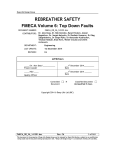
1
SideMount Machine Closed Circuit Rebreather by Anthony Tedeschi Jr Bachelor of Science Ocean Engineering Florida Institute of Technology May 2008 A thesis submitted to Florida Institute of Technology in partial fulfillment of the requirements for the degree of Master of Science in Ocean Engineering Melbourne, FL January 2010 © 2011 Anthony Tedeschi Jr All Rights Reserved The author grants permission to make single copies ________________________ We the undersigned committee hereby approve the attached thesis SideMount Machine Closed Circuit Rebreather by Anthony Tedeschi Jr _____________________________________ Stephen L. Wood, Ph.D., P.E. Assistant Professor Ocean Engineering Major Advisor _____________________________________ Jonathan Shenker. Associate Professor Biological Science Department _____________________________________ Geoffrey W.J. Swain, Ph.D. Professor Ocean Engineering and Oceanography _______________________________________ George A. Maul, Ph.D. Professor & Department Head Department of Marine and Environmental Systems Abstract Title: SideMount Machine Closed Circuit Rebreather Author: Anthony Tedeschi Jr Major Advisor: Stephen L. Wood, Ph.D., P.E. A new type of mixed gas closed circuit rebreather has been developed to give a scuba diver the ability to access smaller passages in an underwater cave or shipwreck. It may also be used as a back up system to a traditional rebreather setup by allowing the diver to carry less backup scuba cylinders, therefore increasing the diver’s safety. The SideMount Machine (SMM) closed circuit rebreather has similar functionality as other commercial available rebreathers on the market such as: Jetstam Technologies Kiss Classic, InnerSpace Systems Megalodon, rEvo and DivRites Optima rebreather. The unique feature of this system is that the rebreather can be worn like a sidemounted scuba cylinder and can be completely removed by the diver and reattached underwater during a dive. This thesis presents the design, construction and field test of the SMM rebreather. The closed circuit rebreather is designed with both an exhale and inhale iii counterlung to allow for greater dwell time of the gas traveling through the loop. The SMM has a radial scrubber design to remove the carbon dioxide in the breathing loop and three oxygen sensors connected to a monitoring system. This enables the diver to see what the oxygen partial pressure is in the breathing loop, to keep them alive. This rebreather is also equipped with a bailout valve to switch the CCR from open circuit to closed circuit and to add diluent gas to the breather loop. The oxygen addition system of the SideMount Machine is a manual add valve, which is connected to an oxygen tank and the diver presses the button to allow the gas to enter the breathing loop. iv Table of Contents List of Figures ......................................................................................................... vii 1. Introduction ............................................................................................................1 1.1 Purpose of SMM CCR ...............................................................................2 2. Background of Diving Equipment .........................................................................5 2.1 Surface Supplied Diving ..................................................................................5 2.2 SCUBA ..........................................................................................................10 2.2.1 Open Circuit Diving ................................................................................11 2.2.2 Closed Circuit Diving .............................................................................12 3. Purpose of Closed Circuit Re-breather ................................................................16 3.1 Military Diving ..............................................................................................16 3.2 Civilian Diving ...............................................................................................16 4. Functionality of Closed Circuit Rebreather .........................................................19 4.1 Breathing Loop...............................................................................................19 4.1.1 Mouthpiece..............................................................................................20 4.1.2 Breathing Hoses ......................................................................................21 4.1.3 Counterlungs ...........................................................................................22 4.1.4 Carbon Dioxide Scrubber ........................................................................24 4.2 Gas Source .....................................................................................................25 4.3 PPO2 Monitoring System ...............................................................................26 5. Existing Technology ............................................................................................27 5.1 Kiss Classic ....................................................................................................27 5.2 rEvo ................................................................................................................30 5.3 Megalodon .....................................................................................................32 5.4 O2ptima ..........................................................................................................33 6. Design Outline .....................................................................................................36 6.1 Breathing Loop...............................................................................................37 6.1.1 Mouthpiece..............................................................................................37 6.1.2 Breathing Hoses ......................................................................................38 6.1.3 Counterlungs ...........................................................................................39 6.1.4 Scrubber ..................................................................................................41 6.1.5 Flow of Gas .............................................................................................44 6.2 Gas Sources ....................................................................................................45 6.3 PPO2 Monitoring System ...............................................................................46 6.4 Scrubber Head ................................................................................................48 v 6.5 Counterlung Housing .....................................................................................49 7. Testing ..................................................................................................................51 8. Conclusion ...........................................................................................................55 9. Recommendations for Future ...............................................................................56 9.1 Modifications .................................................................................................56 9.1.1 Materials ..................................................................................................56 9.1.2 Electronics ...............................................................................................56 9.2 Additions ........................................................................................................57 9.3 Scrubber Testing ............................................................................................57 References ................................................................................................................58 Appendix A – Timeline of the SMM .......................................................................60 Appendix B – SMM Specifications .........................................................................61 Appendix C – Pro Engineer Renderings ..................................................................62 Appendix D – Technical Drawings ..........................................................................67 Appendix E – PPO2 Circuit Schematic ...................................................................72 Appendix F – User Manual ......................................................................................73 vi List of Figures Figure 1 SideMount Machine CCR being worn by diver ..........................................2 Figure 2 Profile View of SMM setup vs. Traditional Setup ......................................3 Figure 3 Edmund Halley's Diving Bell .....................................................................7 Figure 4 Lethbridge’s Diving Suit .............................................................................8 Figure 5 Augustus Siebe’s Diving Dress ...................................................................9 Figure 6 US Navy MK 12 & MK V.........................................................................10 Figure 7 Aqua-Lung .................................................................................................12 Figure 8 Fleuss Diving Apparatus ..........................................................................13 Figure 9 LARU & Draeger Lung Automatic Regenerator V ...................................14 Figure 10 Basic CCR Schematic .............................................................................20 Figure 11 Dive Surface Valve & Bailout Valve ......................................................21 Figure 12 Over the Shoulder Counterlungs .............................................................23 Figure 13 Back-mounted Counterlungs ...................................................................24 Figure 14 Axial and Radial Scrubbers .....................................................................25 Figure 15 Kiss Classic Manual Add Button.............................................................28 Figure 16 Kiss Classic PPO2 Displays ...................................................................28 Figure 17 Kiss Classic Scrubber (grey cylinder) & Head ........................................29 Figure 18 rEvo Dual Scrubber .................................................................................30 Figure 19 rEvo PPO2 Displays & HUD ..................................................................31 Figure 20 Megalodon Canister with mounting hardware ........................................32 Figure 21 Megalodon Head with Displays & Head connected to Canister .............33 Figure 22 Dive Rite O2ptima Rebreather ................................................................34 Figure 23 SMM Cutaway View ...............................................................................37 Figure 24 Kiss Classic BOV ....................................................................................38 Figure 25 Breathing Hoses ......................................................................................39 Figure 26 MSR Dromedary Bags .............................................................................40 Figure 27 Counterlung Connection ..........................................................................41 Figure 28 Scrubber Canister.....................................................................................43 Figure 29 Scrubber Basket .......................................................................................44 Figure 30 1st Stage with blocking plug & Orifice ...................................................45 Figure 31 Oxygen Manual Add Valve .....................................................................46 Figure 32 Sensor Plate with Oxygen Sensors ..........................................................47 Figure 33 PPO2 Display, External Electronics ........................................................48 Figure 34 Scrubber Head .........................................................................................49 Figure 35 Counterlung Case ....................................................................................50 vii Figure 36 Non-Trimmed & Trimmed CCR .............................................................53 viii 1. Introduction The history of professional diving can be traced back more than five thousand years. Man’s relationship with diving is firmly rooted in maritime commerce, in military operations, and in salvage work [1]. There has always been an aspiration to expand underwater frontiers through exploration, research and development of new gear and diving techniques [1]. Original equipment developed in the past, and present technological advancements in dive gear allow mankind to explore farther and deeper into the underwater world. The eventual twentieth century development of basic open-circuit scuba equipment marked the start of the now fully evolved closed-circuit re-breathers. Yet an impasse for modern deepwater divers still exists. There continues to be an increasing need for more reliable essential devices such as multiple re-breathers, backup re-breathers and/or a smaller utilitarian rebreather, which offers the diver a smaller profile while investigating his or her underwater environment. This thesis presents a new rebreather to address these issues. It must be pointed out that the design contained within this document has not been proven outside of the laboratory and should not be used for open water use until a fully tested professionally manufactured system becomes available, Patent Pending. 1 The author and professors that have signed off on this technology are not liable for miss use of this design. 1.1 Purpose of SMM CCR The purpose of the Side-Mount Machine Closed-Circuit Rebreather (SMM CCR), shown in Figure 1 is to enhance the safety and reliability in conducting deeper and/or longer dives, whether the exploration is in the open ocean or maneuvering thousands of feet inside an extensive cave system. The SMM CCR provides the diver with an easily attachable mixed gas rebreather that is worn on the side rather than on the back of a diver. Figure 1 SideMount Machine CCR being worn by diver 2 This added advantage gives the diver the option of using the rebreather as a backup to his or her normal rebreather or to just wear the rebreather on one side and an open-circuit bailout scuba cylinder on the subject’s other side. If using the SMM as a backup rebreather, this innovative method allows the diver to carry less equipment than he or she traditionally would employ if only operating one rebreather. For example, if a diver were to dive to 200 feet for about 30 minutes, he or she would need a minimum of four scuba cylinders for backup safety protection in case the rebreather were to fail. Table 1 shows the amount of gas required for a traditional CCR diver compared to that of a diver wearing the SMM and Figure 2 demonstrates the difference in diver’s profiles between the two setups. Table 1 Gas Capacity Comparison Setup Traditional SMM Bailout # of Tanks 3 Gas Volume Required 171 ft3 1 29 ft3 Figure 2 Profile View of SMM setup vs. Traditional Setup 3 The option of wearing the SMM rebreather on the diver’s side gives him or her the ability to access smaller cave areas or a deep shipwreck because the rebreather can be completely removed and replaced during a dive. Unlike traditional rebreathers that mount on the divers back and cannot be removed during a dive. With the options the Side-Mount Machine offers, the improvement would be very marketable not only to the serious exploration diver who is pushing the limits but also to the typical everyday amateur rebreather diver. The goal of implementing the Side-Mount Machine is not only to provide a reliable rebreather for divers but also to produce an affordable unit that will cost less than the three thousand plus dollar re-breathers currently available in the marketplace. 4 2. Background of Diving Equipment 2.1 Surface Supplied Diving Diving can be traced back more than five thousand years. The adventurous individuals would use surface supplied air to harvest food, coral, exotic pearls, sponges, and would perform salvage work in up to one hundred feet of water depth. These surface supplied units consisted of devices such as breathing tubes, breathing bags, diving bells and diving dresses [1]. Breathing tubes were the most logical and easiest approach to supply a diver with surface supplied air. The diver would use hollow reeds or tubes, long enough to reach the surface. To go to greater depths, the length of the breathing tube was extended; however, this extended tube approach is not feasible beyond three feet in depth due to the body’s natural respiratory ability to counteract the external water pressure. This pressure obviously increases as the diver descended deeper into the water column (Table 2) [1]. 5 Table 2 Depth & Pressure Chart Depth Atmosphere Absolute (ATA) Pressure 0 ft 0m 1 14.7 psi 1 BAR 33 ft 10 m 2 29.4 psi 2 BAR 66 ft 20 m 3 44.1 psi 3 BAR 99 ft 30 m 4 58.8 psi 4 BAR 132 ft 40 m 5 73.5 psi 5 BAR At the beginning of man’s diving explorations, the effects of pressure were not understood completely; therefore, designs such as breathing bags were impractical. Breathing bags were initially designed with the idea of the diver carrying a bag of air. Again, issues involving greater pressure caused this primitive airbag design to be infeasible. Another major issue with early breathing bag design was a practical way to sink the bag due to the bags buoyancy [1]. The standard diving bell development started in 1500 and its adaptations continued into the 1800s. The diving bell is an apparatus with a bell shape that has its bottom open to the water. The early bells were strong tubs with weights attached to allow them to sink in a vertical manner. The vertical positioning of the bell allowed air to be captured, therefore supplying divers with sufficient air for hours rather than mere minutes. These post-medieval diving bells were not very maneuverable and required a surface ship to move and effectively deploy them. The bell was either dropped over the work area or the diver would leave the bell for a short interval, holding his breath and rapidly then returning to the diving bell for air [1]. 6 In the 1680s, William Phipps modified the rudimentary diving bell by supplying his divers with fresh air using a series of weighted inverted buckets. Then in 1690, Edmund Halley combined the diving bell along with a series of weighted inverted buckets, allowing him to adequately replenish the diving bell with fresh air, shown in Figure 3 [1]. Figure 3 Edmund Halley's Diving Bell [1] As maritime commerce expanded, so did the shipwrecks scattering the coast caused by storms, collisions and navigational errors. This newfound phenomenon caused a greater need for a diving dress that provides the explorer with better mobility and efficiency. John Lethbridge developed a completely enclosed oneman diving dress (Figure 4). Wearing this diving dress, an ambitious diver could 7 achieve a depth of approximately sixty feet and stay underwater for almost forty minutes. The diver was able to work efficiently for a longer duration, but the new equipment had the same disadvantage as the diving bell; a surface support vessel was needed to deploy and maneuver the diver [1]. Figure 4 Lethbridge’s Diving Suit [1] At the turn of the 19th century a hand operated pump was developed, and this machine was capable of delivering abundant air under pressure to a diver. In 1828, Deane’s Patent Diving Dress was developed; it consisted of a heavy suit, helmet with viewing ports and a hose to allow surface supplied air to the diver. While Deane’s Diving Dress was a breakthrough in Surface Supplied Diving, it was not the first practical diving dress [1]. The first practical diving dress is accredited to Augustus Siebe, who creatively modified the helmet of Deane’s diving dress by adding a collar to fully 8 seal the helmet around the diver’s neck (Figure 5). Siebe also added an exhaust valve to the helmet to vent excess gas. Siebe’s improved diving dress is the direct ancestor of the United States Navy’s MK V standard deep-sea diving dress [1]. Figure 5 Augustus Siebe’s Diving Dress [1] In 1905, the United States Navy designed the MK V Diving helmet, which was basically Siebe’s Diving Dress with some added safety modifications. The MK V Diving helmet was used until February 1980, the upgraded model featuring only a few small modifications from the helmet’s initial debut in 1905. The MK 12 Surface-Supplied Diving System (Figure 6) succeeded the MK-V and this new unit was replaced by the MK 21 (Figure 6) in December 1993. These improved units were minor upgrades to their predecessor with certain aforementioned advances in construction materials to make them lighter and more efficient. 9 Figure 6 US Navy MK 12 & MK V [1] 2.2 SCUBA The development of diving equipment engineered by John Deane, Augustus Siebe and other early lesser-known contributors gave men the ability to work underwater for extended time periods. Despite this obvious progress, work was still limited by the need of a surface vessel to support the divers. A better solution was to have a mobile, self-contained supply of air. SCUBA or Self-Contained Underwater Breathing Apparatus only existed in an abstract hypothetical realm. This revolutionary diving method was theoretical for many years but its technology could not be developed because of limitations in contemporary air pumps and requisite containers to hold the compressed gas. Scuba gradually evolved and separated into two distinct divisions: Open-Circuit Scuba (Exhaled gas is vented to the surrounding environment) and Closed-Circuit Scuba (Oxygen is filtered and recirculated back to the diver) [1]. 10 2.2.1 Open Circuit Diving In 1866, Benoist Rouquayrol designed Rouquayrol’s Demand Regulator. The regulator adjusted the higher pressure from a container to a lower breathable pressure that the diver could use. This regulator was the first necessary tool for an open circuit scuba system but containers to hold the desired breathing gas could not hold high pressure; therefore, the regulator was adapted for surface supplied diving. It was not until 1933 that research on open circuit scuba development began again. A French naval officer, Commander LePrieur successfully built an open circuit scuba system using a compressed air tank. Because his device did not have a demand regulator, the diver had to constantly control the flow of air. The lack of a demand regulator caused the diver to focus too much on air control and not enough on his mission [1]. During WWII in France, Jacques-Yves Cousteau and Emile Gagnan achieved a breakthrough in open circuit scuba. They improved on Rouquayrol’s Demand Regulator and subsequently upgraded their predecessor’s work with highpressure air tanks to create the first open circuit scuba unit commonly known as the Aqua-Lung (Figure 7). Their dual effort was a combination of years of progress and blending the work of different developers. At the termination of WW II, the Aqua-Ling quickly became a huge commercial success and it is still the most widely used diving equipment [1]. 11 Figure 7 Aqua-Lung 2.2.2 Closed Circuit Diving The basic closed-circuit rebreather or oxygen rebreather uses a tank of one hundred percent oxygen to supply a breathing bag, into which a diver takes a breath. The exhaled gas from the diver is then re-circulated through a chemical filter, with the purpose of removing carbon dioxide from the exhaled gas. The oxygen metabolized by the diver is efficiently replenished from the tank of pure oxygen carried by the diver. The first practical commercial closed-circuit system (Figure 8) was developed between 1876 and 1878 by Henry A. Fleuss. This closed-circuit scuba system consists of a copper tank containing pure oxygen and a watertight facemask having a breathing bag attached. The early models of the Fleuss device controlled oxygen addition with a hand valve, which the diver controlled. Development of the 12 Fleuss system continued with the addition of a higher-pressure oxygen cylinder and accompanying demand valve regulator [1]. Figure 8 Fleuss Diving Apparatus [1] In the late 1940s Dr. C.J. Lambarteen proposed the use of a Mixed-Gas Rebreather because oxygen becomes toxic to the human body on descents deeper than twenty feet. This unique rebreather was based on the same concept as the oxygen rebreather, but instead of inhaling pure oxygen, the diver would have a gas mixture containing nitrogen and/or helium combined with heightened oxygen content. This new mixture would allow for practical underwater usage beyond the depth range (20 feet) of an oxygen rebreather. Then in the early 1950s Dr. Lambertsen introduced the FLATUS I, which was a semi-closed-circuit system that continually, added a small volume of mixed gas into to the breathing loop. This 13 gas is then re-circulated, the carbon dioxide is removed and excess gas is vented out of the breathing loop. During WWII the U.S. Navy enhanced and deployed the Lambertsen Amphibious Respiratory Unit (LARU). In the post war years that followed the LARU (Figure 9) was replaced by the Emerson-Lambertsen Oxygen Rebreather. The Emerson unit was eventually substituted by the Draeger Lung Automatic Regenerator (LAR) V (Figure 9), and is still used by US Combat Swimmers [1]. Figure 9 Lambertsen Amphibious Respiratory Unit & Draeger Lung Automatic Regenerator V [1] It was not until the beginning of 1979 that the MK 15 closed-circuit rebreather was manufactured and implemented into the US Navy Diving Program. The MK 15 is a constant oxygen partial pressure rebreather, whereby the oxygen content is controlled at a constant rate and is monitored by an oxygen sensor. This 14 unit is used when missions are deeper than an ordinary oxygen rebreather will allow [1]. 15 3. Purpose of Closed Circuit Rebreather 3.1 Military Diving The United States Navy began using closed circuit rebreathers for combat missions during WWII. The U.S. Operational Swimmer used the LARU in special missions during wartime. This CCR gave the diver the advantage of being bubbleless and stealthier than swimming with traditional open-circuit scuba. Today the U.S. Navy has two separate groups of combat swimmers: Explosive Ordnance Disposal (EOD) and Navy Air and Land (SEAL) special warfare teams. Both groups take advantage of the CCR because of the overall silence and the bubblefree surroundings these units offer [1]. This extraordinary functionality gives the combat swimmers the ability of approaching enemy targets undetected during combat missions, as well as increasing safety when working with explosives, which may detonate due to immediate turbulence caused by the bubbles of an open-circuit scuba system. 3.2 Civilian Diving The human urge to explore unknown areas can be dated back as far man’s fascination with the unknown existed. As technology has developed and more 16 people have wandered the globe, remote areas of exploration are becoming fewer. These unexplored areas of the underwater world now exist at much deeper depths than before (and/or in more remote locations). The functionality of a closed circuit rebreather allows for easier access to more difficult dive sites because the device requires less gas and can be used for a longer duration than traditional open-circuit gear. Since the rebreather recycles the gas used by the diver, it is lighter than an open circuit scuba setup. This important characteristic allows for easier mobility when traveling greater distances to explore in remote locations. Transportation to arrive at given destinations may range from small plane access, slow donkey passage or having to walk through a dense jungle. The first major advantage of the CCR is that it is not depth-dependent; its operational duration does not change whether the diver is at twenty feet or two hundred and twenty feet. This significant advantage again benefits the diver by allowing him or her to descend deeper into a sea or lake or stay underwater longer than traditional scuba gear permits. The second advantage of the Closed-Circuit Rebreather is that a diver can perform many long or deeper dives again and again using the same rebreather. The traditional open circuit diver requires multiple sets of tanks and decompression tanks. The third practical advantage of a CCR is the absence of bubbles; this differentiation offers two benefits to the diver. First the diver is virtually silent, and second allows the diver to move closer to marine life without disturbing it, e.g. documenting wildlife with photographs or video. 17 Ostensibly, the absence of bubbles shooting-up from the diver is not-at-all evident. His singular presence will have little or no an impact on an observable environment such as a pristine shipwreck where the possibility of the bubbles dislodging rust or silt has been satisfactorily eliminated. When these vulnerable elements are disturbed, the falling debris reduces the diver’s visibility. Better visibility allows for the diver to navigate more safely [2]. 18 4. Functionality of Closed Circuit Rebreather The Closed Circuit Rebreathers come in a variety of shapes and sizes; however, when broken down into the most basic components the variations all contain the same fundamental parts and perform the same function, which is to recycle the gas the diver uses [3]. These fundamental parts can be classified into three sections: the Breathing Loop, the Gas Source, and the Partial Pressure (PPO2) monitoring system. The only difference between the separate manufacturers’ designs is how the companies package these components into the CCR [3]. In the figure below the basic CCR design and gas flow through a rebreather is shown. 4.1 Breathing Loop A breathing loop on a CCR is a sealed oval apart from the surrounding water into which the diver is immersed, and the contained gas moves from start to finish in one continuous loop. The process begins with a mouthpiece that the diver exhales air into. The gas travels from the mouthpiece into a breathing hose and next into the exhale counter-lung. From the counter-lung the gas travels into the carbon dioxide scrubber and then exits into the inhale counter-lung. From the 19 inhale counter-lung the gas travels through a breathing hose back to the mouthpiece, the genesis from where the diver receives another breath. Figure 10 Basic CCR Schematic [3] 4.1.1 Mouthpiece Two types of mouthpieces commonly found on a Closed Circuit Rebreather are the Diver Surface Valve (DSV) and the Bailout Valve (BOV), and depending upon which type the unit is equipped, the mouthpiece’s identity is determined. The DSV (Figure 11) operates with the use of a two-position lever on the mouthpiece, either indicating “open” or “closed.” When the lever is in the “open” 20 position, the loop is open and the mouthpiece must be in the diver’s mouth. When the lever is in the “closed” position the loop is shut and sealed from the surrounding environment. The BOV (Figure 11) has dual-purpose functionality; it acts as a DSV but has a second stage built into it as well. This capacity allows the diver to switch from closed circuit to open circuit by closing the DSV, therefore closing the loop and opening up access to open circuit via the second stage regulator. Figure 11 Dive Surface Valve [9] & Bailout Valve [5] 4.1.2 Breathing Hoses The breathing hoses are attached to the mouthpiece and allow the exhaled gas from the diver to travel into the counterlung/scrubber. The gas then travels back to the diver when inhaling from the scrubber; the gas next travels to the counterlung and then passes back to the mouthpiece. The type of hose that is standard throughout the industry is composed of corrugated rubber. The object’s 21 length ranges from approximately seven inches to twenty two inches depending on the particular rebreather setup and design. 4.1.3 Counterlungs Counterlungs on a rebreather act as external lungs for the diver and they should match as close to the diver’s tidal volume as possible. When a diver exhales into the loop, the exhaled breath automatically fills the exhale counter-lung; then the gas travels through the scrubber and next back into inhale counter-lungs. This process allows for the gas in the loop to sufficiently dwell, causing an improved mix with the new gas added to the loop, thus providing the scrubber more time to work. The two main setups for counterlungs on a rebreather are the over the shoulder counterlung (Figure 12) and the back-mounted counterlung (Figure 13). The over the shoulder counterlungs connect to the diver’s harness and come to rest in front of the diver’s body. This specific symmetry offers a more propitious hydrodynamic gas flow inside the loop (in a horizontal trim position). Consequently, the apparatus allows for less-demanding breathing effort. The disadvantage of the over the shoulder counter-lung is its vulnerability to sharp objects such as the masts of shipwrecks or cave ledges. The counter-lungs can also cause the diver’s chest to be cluttered, making it more difficult to clip and unclip necessary accessories to their harness. 22 Figure 12 Over the Shoulder Counterlungs [9] Back-mounted counter-lungs give the diver the ability to have his or her chest area clean and clear of obstacles since the counter-lungs are mounted in a case behind the diver, usually situated higher on the shoulder blades. The disadvantage of this type of counter-lung is the increase breathing effort resulting from the differences in hydrostatic pressure in counter-lungs’ placement compared to the ordinary functioning of diver’s lungs. 23 Figure 13 Back-mounted Counterlungs [5] 4.1.4 Carbon Dioxide Scrubber The scrubber removes the carbon dioxide that the diver exhales into the loop during his or her exhalations. The gas moves into the scrubber canister, advances through the scrubber material and next transports back out into the breathing loop. There are two types of scrubber designs: the axial scrubber and radial scrubber (Figure 14). Both remove carbon dioxide from the diver’s exhaled gas but the way the gas flows through the scrubber median differs. An axial scrubber is designed to have the breathing gases move from top to bottom (or viseversa) through the scrubber median [4]. Conversely, the design of a radial scrubber is to have the breathing gas move from the middle to the outside (or vise-versa) through the scrubber material [4]. There are divergent claims by different divers about the radial scrubber having an advantage over the axial scrubber, but to date, there has not been any convincing published evidence to prove this speculation and the argument continues to be dominated by personal opinion. 24 Figure 14 Axial [7] and Radial [10] Scrubbers The scrubber median used in rebreathers is soda lime and consists of the following components: Calcium hydroxide (Ca(OH)2), water (H2O), Sodium hydroxide (NaOH) and Potassium hydroxide (KOH). The reaction takes place along a front, which is the cross section of the scrubber canister. When the exhaled carbon dioxide passes along the front of the soda lime it reacts and is converted to calcium carbonate (CaCO3). 4.2 Gas Source All mixed gas Closed Circuit Rebreathers have two gas supplies to function properly. The first gas supply is oxygen, providing the diver with the needed oxygen that is removed from the loop after every breath is taken. The other gas, called “diluent” is usually air or some kind of trimix (Trimix is a diving gas used 25 with a combination of nitrogen, oxygen and helium). This gas is meticulously fed into the rebreather as a diver moves deeper in the water column and because of the increase in surrounding pressure; the diluent is added to provide the recipient with an adequate volume of gas to fill their lungs when taking a breath. 4.3 PPO2 Monitoring System The PPO2 or Partial Pressure of Oxygen monitoring system measures the PPO2 in the rebreather loop and then the readout is visually displayed to the diver. The monitoring system consists of at least three oxygen sensors, which are usually mounted in the main rebreather canister. The items are then wired to an electrical display outside of the CCR and secured inside a waterproof housing especially designed to allow the diver to monitor the oxygen levels. 26 5. Existing Technology Currently the closed-circuit rebreather market has over a dozen different rebreather models being produced but all are considered back-mounted rebreathers. A back- mounted rebreather is a unit that is worn on the diver’s back in a similar manner that a hiker would wear a backpack; whereas, an open-circuit diver would wear a set of doubles. Side-Mounted Rebreathers are not currently available commercially and although there are a few companies doing research and development, the methodology is still in its infancy as far as commercial units are concerned. The back-mounted units with good track records for dependable functionality currently available on the market are the Kiss Classic, the rEvo, the O2ptima and the Megalodon. These exceptional units are also being used to push the limits in recreation diving and in technical professional exploration. 5.1 Kiss Classic The Kiss Classic Rebreather was designed with the philosophy of keeping the device simple. This closed-circuit rebreather is a buffered manual control unit and it is mixed gas capable. This basic description means that the unit has a constant flow of oxygen being added into the loop through a small orifice, and the 27 concurrent flow rate is set to meet the diver’s oxygen requirements. If the diver needs to add more oxygen to the loop, the CCR is conveniently equipped with a manual add button (Figure 15), which the diver simple presses to facilitate more oxygen entering the loop [5]. Figure 15 Kiss Classic Manual Add Button [5] The partial pressure oxygen display (Figure 16) for the Kiss Rebreather demonstrates three independent displays. Each of the three displays maintains its own housing, LCD screen, battery and additionally, each unit is connected to its own oxygen sensor (O2 sensors are mounted in the head of the CCR). This illustrated PPO2 display setup makes the unit completely redundant and highly unlikely to ever completely fail [5]. Figure 16 Kiss Classic PPO2 Displays [5] 28 The scrubber design of the Kiss Class is an axial flow canister (Figure 17), which holds about six pounds of scrubber median. The scrubber is attached to the head of the CCR (Shown in Figure 17, and it is the black piece located above the scrubber). This scrubber is rated for about three hours of use, representing a flow of about one liter per minute of carbon dioxide expended by the diver [5]. Figure 17 Kiss Classic Scrubber (grey cylinder) & Head [5] This pictured rebreather is equipped with a BOV for its mouthpiece and has back-mounted counterlungs. The counterlungs are placed inside an aluminum housing and attached to the CCR’s head. The Kiss Classic is equipped with an automatic diluent valve (ADV), which enables the diver to add diluent gas into the breathing loop without having to press any additional buttons. The ADV as shown in Figure 17, is located in the head of the rebreather near the right side [5]. 29 5.2 rEvo The rEvo is a mixed gas fully closed-circuit rebreather with back-mounted counterlungs. The unit comes standard with an axial scrubber (Figure 18) but has an uncommon dual canister design. This selfsame dual design splits the scrubber material into two separate canisters instead of possessing just a single canister scrubber like most other rebreathers sold on the market. It is claimed by the manufacturer that the dual design allows for better performance of the scrubber material and the industrial specifications simultaneously increase the device’s safety. Figure 18 rEvo Dual Scrubber [6] The rEvo CCR can be set-up in three different ways: as a manual, as a hybrid or as a fully electronic rebreather [6]. Setting-up this unit to work manually, the device operates like the Kiss Classic Rebreather; when set-up to run electronically, the rebreather controls and monitors everything in the system 30 automatically [6]. The hybrid is the most unique feature of the rEvo. When using the hybrid method, the rEvo has a constant flow of oxygen like the Kiss Classic does, but if the PPO2 drops below the diver’s required set point, the rebreather will automatically add more oxygen to the breathing loop through an electronic solenoid. The rEvo is also equipped with a DSV mouthpiece and manual-add-buttons for oxygen and diluent gas addition. As well as an ADV, two independent PPO 2 displays and Heads Up Display (HUD) are graphically shown in Figure 19. A Heads Up Display, is a small multi-colored light display and it is attached to the mouthpiece and allows the diver to monitor the contents of the breathing loop by viewing the lights. Depending on the colors and/or blinks, the signal notifies the diver of the loop’s contents as well as permitting the diver’s hands to be free to work. The two displays each show a reading from different oxygen sensor and the HUD shows the third oxygen sensor [6]. Figure 19 rEvo PPO2 Displays & HUD [6] 31 5.3 Megalodon The Megalodon (Meg) Rebreather is an electronic CCR and just as the other rebreathers previously mentioned, it comes with an ADV, HUD and manual-addbuttons for gas addition and DSV. This Meg unit differs from the Kiss and rEvo since it has over the shoulder counterlungs and the entire device is built around the canister (Figure 20), which incidentally holds the scrubber. The standard scrubber for the Meg is an axial design; it holds about five and half pounds of scrubber median and is placed inside the canister [7]. Figure 20 Megalodon Canister with mounting hardware [7] The Megalodon’s core is the head (Figure 21), which holds the solenoid, oxygen sensors, batteries and electronics. The three oxygen sensors are mounted in the head’s middle, inside a sensor carriage. The head is attached to the top of the Meg’s canister with the electronics and sensors being stored inside the canister, shown in Figure 21. From the top of the head comes two separate wire cords, 32 which connect to independent displays (Figure 21) to allow the diver to monitor the breath loop PPO2 levels [7]. Figure 21 Megalodon Head with Displays & Head connected to Canister [7] 5.4 O2ptima The Dive Rite O2ptima (Figure 22) is a fully closed circuit re-breather and a constant PO2 electronically controlled unit featuring a built in decompression ability. The equipment has over the shoulder counterlungs similar to the Meg’s and has the same functionality such as: DSV, oxygen and diluent add buttons, ADV, three oxygen sensors and HUD [8]. 33 Figure 22 Dive Rite O2ptima Rebreather [8] The biggest difference with the O2ptima re-breather design is its use of an Extend Air cartridge for its scrubber. The scrubber is still an axial design like the others, but the scrubber median is sprayed onto a permeable material. Once dry, it is rolled up and cut to fit inside the scrubber canister. This adaptability allows the diver to have pre-packaged scrubber advantage and it saves him or her valuable time and effort making sure that their scrubber is properly installed. The second big difference in the O2ptima compared to other already described re-breathers is its scrubber location. Unlike the other systems, Dive Rite’s scrubber is located behind the diver’s neck in what constitutes a horizontal position. This unique design makes it nearly impossible for water to come into contact with the scrubber in the event of a flood [8]. 34 Table 3 Comparison Overview Rebreather Counterlung Manual Electroinc BOV ADV Oxygen MAV Diluent MAV Scrubber Type PPO2 Displays HUD Dimensions Kiss Classic Back-mounted Yes No Yes Yes Yes No Axial Yes No 21” x 14” x 8” 54cm x 36cm x 20cm rEvo Back-mounted Yes Yes No Yes Yes Yes Axial Yes Yes 25” x 15” x 8” 64cm x 38cm x 20 cm 35 Megalodon Front-Mounted No Yes No Yes Yes Yes Axial Yes Yes NA Optima Front-Mounted No Yes No Yes Yes Yes Axial Yes Yes 25” x 13” x 7” 64cm x 33cm x 18cm 6. Design Outline The SideMount Machine (SMM) as introduced in these thesis by the author follows the same philosophy of “keeping it simple” as the Kiss Classic does. This product is a rebreather system that is a fully closed circuit mixed gas rebreather, promoting constant mass flow oxygen control inside the system. The SMM Rebreather can be used two ways. The first implementation is as a primary unit, worn on the diver’s side, similar to an open circuit side-mounted cylinder, but much smaller and less cumbersome. Used this way, the device allows the diver to have a smaller vertical-yet-wider profile in the water. The SMM allows the diver access to smaller exploratory areas, which under normal circumstances could not be reached with a traditional back-mounted rebreather. The SMM could also be used as a backup re-breather, worn easily as a Side-Mount tank; in addition to the diver wearing a traditional back mounted re-breather. The Side-Mount Machine is easily accessed for use should the primary re-breather fail. 36 Figure 23 SMM Cutaway View 6.1 Breathing Loop 6.1.1 Mouthpiece The current rebreather market has a variety of proven and remarkable functioning mouthpieces. Mouthpiece selection is based on the diver’s preferences and the type of diving he or she performs. The SMM design uses a bailout valve mouthpiece, which is the same that is used in the Kiss Classic’s BOV, as shown in Figure 24. 37 The design decision to use the Kiss Classic’s BOV mouthpiece was threefold. The first apparent reason is increased diver safety. Should the system fail while being tested, the underwater participant could easily flip the switch and then be on open circuit scuba. The versatile mouthpiece could also be used as an additional gas valve since the initial design of the SMM does not have an automatic diluent valve. This BOV mouthpiece has a proven record for functionality and reliability. Figure 24 Kiss Classic BOV 6.1.2 Breathing Hoses The breathing hoses (Figure 25) for this Kiss Classic design are the standard rubber corrugated rebreather hoses used on most rebreathers today. The inner diameter of these hoses is 1.5 inches and the length will be 22 inches for the inhale side and 17 inches for the exhale side. The later adjusted water-use length 38 was chosen after pictures showed excess hose utilization with a 22 inch hose on the mouthpiece’s exhale side; therefore after experimentation, a 17 inch hose was constructed and tested, ultimately proving to be a more suitable choice. The breathing hoses float when in water and three stainless steal hose weights are placed on each hose to weigh them down, and coincidentally increase the comfort of the mouthpiece. Figure 25 Breathing Hoses 6.1.3 Counterlungs The counterlungs employed for the SideMount Machine Rebreather are MSR Dromedary Bags (Figure 26) that can easily be purchased from any hiking or camping store. The bags also come in a variety of sizes to accommodate the specific lung volumes of different sized divers. These bags are designed to hold drinking water; hence, they work great for counterlungs and are easy to clean, eliminating any likelihood of egregious bacterial growth. 39 Figure 26 MSR Dromedary Bags Two counterlungs are used in this design, one on the exhale side and one on the inhale side. This separation allows for an increase in “dwell time,” which indicates that the gas traveling through the loop moves slower to allow the scrubber material to work more efficiently. Each counterlung is connected to the rebreather through a counterlung connection (Figure 27). The MSR bag slides over the opening on the counter-lung connection and is secured in place by the containing ring (Black ring in Figure 27). The connections are constructed of schedule 40 PVC, commonly used to transport drinking water. 40 Figure 27 Counterlung Connection 6.1.4 Scrubber Of the two types of scrubber designs already identified as “axial and radial,” the axial, with its proven efficacy and ease of design, was eventually chosen for daily use over its counterpart rival. The radial scrubber was finally ruled out because of lack of sufficient proven research that it is better or more efficient than the axial scrubber. The dimensions of the acknowledged radial scrubber evolved from US Navy Scrubber recommendations and the commercial scrubber design of the Kiss Classic. The Navy recommendation for scrubber design for a re-breather with a three-hour duration has the following requirements [11 & 12]: Cylindrical Tube Design with minimum of ¼ inch wall thickness Length to Diameter Ratio = 3.02 Scrubber length 12.28 inches (31.19 cm) 41 Scrubber diameter 4.06 inches (10.31 cm) Bottom spacing/water trap minimum of 1.18 inches (2.99 cm) Scrubber Endplates o Non-corrosive, nonmagnetic materials o Rim between 0.39 to 0.59 inches (0.99 to 1.49 cm) o Hole openings less or equal to 0.78 inches (1.98 cm) & at least 35 % open area The Kiss Classic scrubber has a rated duration of three hours and has the Dimensions as follows: Cylindrical Tube Design with ¼ inch (0.63 cm) wall thickness Length to Diameter Ratio = 2.39 Scrubber length 11.25 inches (28.57 cm) Scrubber diameter 4.7 inches (11.93 cm) The scrubber design for the SMM (Figure 23) took into account the Navy recommendations, the Kiss Classic design, and finally, material availability to produce a scrubber with the following dimensions: Cylindrical Tube Design with ¼ inch (0.63 cm) wall thickness Length to Diameter Ratio = 2.55 Scrubber length 12 inches (30.48 cm) Scrubber diameter 4.7 inches (11.94 cm) 42 The scrubber canister is constructed of gray cylindrical PVC tube and the bottom is permanently capped with a piece of solid “delrin,” which is secured with PVC cement. Figure 28 Scrubber Canister The scrubber basket (Figure 29) is dropped inside the scrubber canister and the scrubber material will then be packed around the center tube, filling most of the canister. The end caps are made from delrin with a stainless steel mesh screen glued to act as a filter to efficaciously keep the scrubber material in place. The end caps are designed to meet or exceed the stringent Navy recommendations listed above. The center tube is constructed of schedule 40, one-inch (2.54 cm) PVC tube and one end is attached with PVC cement to a scrubber end cap. 43 Figure 29 Scrubber Basket 6.1.5 Flow of Gas The gas flow starts from the diver’s exhalation and travels through the exhalation side breathing hose. From there the gas will travel to the exhalation counterlung. It will then move from the counterlung traveling down the center tube of the scrubber. When the gas reaches the end of the tube, it mushrooms out from the center and flows back up through the scrubber material. The gas then passes from the bottom, to the top, through the entire scrubber median. When the gas reaches the top of the scrubber it travels past the oxygen sensors and into the inhale counterlung; from there the gas flows through the inhale-breathing-hose side and back into the diver’s mouth. The gas is moved through the loop by the diver’s exhale (pushing the gas) and inhale (suction). 44 6.2 Gas Sources For any closed-circuit rebreather to function there needs to be a way for both oxygen and diluent to be measurably added into the breathing loop. The oxygen is added into the exhale side of the loop to promote it to travel through more than half the loop, allowing it to mix evenly. It is quantitatively introduced into the system via an orifice valve (Figure 30) at a gas flow rate just under the diver’s metabolic oxygen consumption. This practice is done by inserting a blocking plug into the oxygen, thus consummating first stage (Figure 30) and the precise mixture keeps the intermediate pressure from changing with depth, in turn keeping the flow of oxygen constant at any depth. Figure 30 1st Stage with blocking plug & Orifice The oxygen can also be added to the loop using a manual-add-valve, in case the orifice valve is not providing enough oxygen; therefore, the diver can simply add optimal gas into the system by pressing a button (Figure 31). 45 Figure 31 Oxygen Manual Add Valve The diluent gas will be added to the system with the mouthpiece via the bailout valve. As the loop volume decreases, the diver will switch the BOV to the open-circuit position, inhale, and next switch the BOV back to closed circuit adjustment and then exhale back into the loop. 6.3 PPO2 Monitoring System The only electronics evident in the SMM’s rebreather design is present inside the partial pressure oxygen monitoring system. This system consists of two sections, the internal electronics, which are housed inside of the breathing loop and the external electronics, which will be attached to the diver. The internal electronics consist of three oxygen sensors and each sensor is connected to two different wires, which are connected to the primary display and the backup display. The oxygen sensors are mounted to a sensor plate (Figure 32), which is housed in the head of the CCR, and the indicator reads the oxygen content before it travels to 46 the inhale counterlung. The wires pass through the top of the head and each circuit is attached to separate waterproof connectors. Figure 32 Sensor Plate with Oxygen Sensors The external electronics consist of two separate displays encased in waterproof housings (Figure 33). Each display shows the three separate oxygen sensor readings, by converting the “milli-volt” reading the oxygen sensor outputs into a partial pressure oxygen reading. This transfer gives the unit redundancies for the PPO2 readings and using analog circuitry, it adheres to the philosophy of the SMM design in “keeping it simple.” 47 Figure 33 PPO2 Display, External Electronics 6.4 Scrubber Head The SMM’s scrubber head (Figure 34) is the rebreather’s core; it houses the three oxygen sensors, two through holes for both exhale & inhale counterlungs, as well as containing the scrubber canister’s connection point. The delrin head was machined from a six-inch (15.24 cm) rod stock by a computer numerical control (CNC) machine. There are two 1-inch (2.54 cm) schedule 40 PVC tubes coming from the top of the scrubber, which are connected to the counter-lung connections. These tubes allow the gas to flow from the diver’s mouth through the system and then back to the diver. 48 Figure 34 Scrubber Head 6.5 Counterlung Housing The counterlung housing (Figure 35) of this rebreather is constructed from schedule 40 PVC and encloses the counterlungs to protect them from the surround environment. The housing’ slides over the two counterlungs, and a rubber coupling secures the counterlung housing and rebreather head. A small stainless steel hook is mounted to the top half and acts as an attachment point for the CCR to the diver. Another extra large bolt snap is secured to the middle of the rubber coupling and is the attachment point for the bottom of the SMM. 49 Figure 35 Counterlung Case 50 7. Testing A certified closed circuit rebreather diver tested the efficacy of the SideMount Machine Rebreather. Completed in two phases, the obtained results were compared to a comparable available commercial unit. The first testing phase was to assure the “work of breathing” and to assure that the design was within reason, constructed correctly to prevent leakage, as well as to confirm that the PPO2 displays functioned properly. The second testing phase was performed in order to utilize the unit in normal diving conditions and thus confirm the results of phase one testing. The method of testing can be interpreted in the following table provided. 51 Table 4 Phase 1 Testing Test Positive & Negative Pressure Test Land Test Pool Test Dive Simulator Purpose To make sure the re-breather was sealed, not allow gas in escape or enter the system. Duration 10 minutes Used the re-breather on land to make sure it was properly removing the carbon dioxide. Duration 1.5 hours Used the re-breather in the pool to check for any leaks not detected by the positive and negative test, and to check the WOB of the re-breather’s design. This check also allowed the test diver to determine how the unit had to be trimmed out (Figure 36). Duration 20 minutes. Fed the electronics different millivolt reading to simulate change in PPO2, in order to check proper operation. Phase 1 allowed the testing of the individual components and to confirm that the design had been done properly as to not having a rebreather with an unacceptable high WOB. The SMM did not have PPO2 electronics connected during Phase 1 testing; therefore, the breathing loop was flushed and fresh gas had been added about every ten to fifteen minutes. This careful analysis was performed to make sure that the diver’s PPO2 did not fall below 0.16, which logically and scientifically becomes unsustainable once it registers below that level. All phase 1 tests were passed, thus confirming that the SMM was both designed and functioning properly. 52 Figure 36 Non-Trimmed & Trimmed CCR Phase 2 testing differed from phase 1 in that both systems were tested together. The test diver entered the pool, checking for leaks, and spent 15 minutes determining if the scrubber was operating appropriately for the designed time range. Table 5 Phase 2 Testing Test Land Test Pool Test Purpose Used the re-breather on land to make sure it had been properly removing the carbon dioxide and ascertaining that the PPO2 displays were operating correctly. Duration was 15 minutes Continued the land test in the pool, making sure that the CCR did not leak and verifying that the electronics had been working properly. Duration 2 hour 53 After conducting the land test and pool test for Phase 2 the SMM CCR passed as it was expected to as can be seen in the table above. The next step for testing of the SMM is to bring to a shallow (20-30’ range) open-water type environment. From there it would need to be incrementally tested on deeper and longer dives. 54 8. Conclusion As the diver’s needs increase, his purpose being either professional or recreational, the necessity for smaller, modular, simpler and cheaper equipment evolves forward in the direction of more practical diving device applications. The objective of creating the SideMount Machine rebreather is to provide an alternative safe and efficient type of diving equipment capable of offering all of the above listed features to either the experienced or amateur diver. With this current contemporary design, the SideMount Machine ClosedCircuit Rebreather affords the diver the opportunity of accessing remote diving locations, smaller areas in overhead environments such as caves or shipwrecks, and/or allow him or her the ability to safely and more efficiently dive deeper. 55 9. Recommendations for Future In order to make the Side-Mount Machine Closed-Circuit Rebreather a more acceptable commercial-quality design, a few detailed adjustments to its construction have to be modified and/or added. 9.1 Modifications 9.1.1 Materials First, designers must replace the PVC schedule 40 tubing and elbows with delrin tubing and elbows. The inhale and the exhale tubes that connect to the head of the re-breather should have threaded ends to allow them to be replaced should they ever be damaged, and this particular modification will give them a more secure fixture to the scrubber head. The counterlung connections can also be machined from delrin material instead of their current construction of PVC plumbing parts, and their size profile can be satisfactorily decreased. The stainless steel inlet for oxygen is secured with epoxy and it thus could be modified, changed to be precisely threaded into the elbow. 9.1.2 Electronics A printed circuit board (instead of a breadboard currently used) allows for a professional look and its utilization reduces the size of the electronics 56 configuration. Fisher connectors attached to a scrubber head (instead of the current waterproof connector) can be initiated in order to allow after market PPO2 displays and dive computers to be integrated within the system. 9.2 Additions If used either as a decompression rebreather or as a bailout rebreather, the unit needs an automatic diluent valve (ADV) and an over-pressurization valve (OPV). The ADV will allow diluent gas to be automatically added to the loop as the diver descends, obviously preventing the rebreather from imploding. Once the diver begins his or her ascent back to the surface, the gas in the loop expands and an OPV is then needed to vent the excess gas. Since the current SMM can be used as a primary rebreather, the diver can add and remove gas as needed during either his or her descent or ascent. 9.3 Scrubber Testing To be profitably sold in the commercial marketplace, the SideMount Machine Rebreather will need additional laboratory testing. This required testing should be objectively conducted by independent laboratories and should decisively assess maximum scrubber-duration capability. This responsible testing would simulate a diver’s underwater activities under extreme submerged swimming conditions. 57 References [1] United States Navy. U.S. Navy Diving Manual, Revision 6. Naval Sea Systems Command, April 2008. [2] Technical Diving International. Intro to Tech. 2009. [3] Advanced Diver Magazine. Retrieved September 1, 2010, from http://www.advanceddivermagazine.com/ [4] Rebreathers Worldwide. Retrieved September 1, 2010, from http://www.therebreathersite.nl/ [5] Kiss Rebreathers. Retrieved September 1, 2010, from http://www.kissrebreathers.com/kissclassic.html [6] rEvo Rebreathers. Retrieved September 2, 2010, from http://www.revo-rebreathers.com/#/en/home/ 58 [7] The Megalodon Rebreather. Retrieved September 2, 2010, from http://www.customrebreathers.com/meg.html [8] Dive Rite. Retrieved September 2, 2010, from http://www.diverite.com/ [9] Rebreather World. Retrieved September 5, 2010, from http://www.rebreatherworld.com/ [10] Golem Gear. Retrieved September 6, 2010, from http://www.golemgear.com/ [11] Goodman, LCDR M.W. “Carbon Dioxide Absorbtion Systems for SCUBA. 1. Quantitative Consideration of Design and Performance and Performance of Cylindrical Cansisters,” U.S. Navy Experimental Diving Unit, January 15, 1965. [12] Huseby, H.W.S. & Michielsen, E.J. “Carbon Dioxide Absorbent Evaluation and Canister Design & Letter Report,” U.S. Navy Experimental Diving Unit, November 6, 1959. 59 Appendix A – Timeline of the SMM August 2010 Initial rebreather designs sketched and Counterlung Connections designed/constructed. September 2010 Proposal of Design for the SideMount Machine Closed-Circuit Rebreather Completed. October 2010 Scrubber design finalized and SMM was constructed. Initial testing was conducted and modifications made. Electronics for PPO2 display were designed, constructed, and tested. November 2010 Watertight housing for PPO2 displays designed and constructed. Phase 2 testing of the SMM completed. 60 Appendix B – SMM Specifications Table 3 SMM Specifications Weight w/ a full steel low pressure 12ft3 tank, and full scrubber Dimensions (Height x Diameter) Constant Mass Flow Manual Add Valve for Oxygen Trimix Compatible Depth Rating Scrubber Absorbent Lb 29” x 8” Yes Yes Yes 300 feet saltwater 8 lbs 61 Appendix C – Pro Engineer Renderings 62 63 64 65 66 Appendix D – Technical Drawings 67 68 69 70 71 Appendix E – PPO2 Circuit Schematic 72 Appendix F – User Manual Parts List 1 Counterlung case (either 6 or 8 inch) with utility hook, rubber connection boot and rear connection attachment. 1 Scrubber Head with counterlung connections & tubing attached 2 Counterlungs (selection from 2 or 4 liter) 1 Oxygen first stage with delrin plug, OPV and HP button gauge 1 Oxygen Addition System which includes (Already Assembled): o 1 LP hose with orifice o 1 Checkvalve o 1 Y block manifold o 1 Manual Add Valve o 1 Quick Disconnect Check valve o 1 LP hose with Quick Disconnect o 1 LP hose to connect MAV to Scrubber Head 1 Scrubber Canister 1 O-ring Set, includes: o 2 Scrubber Canister O-rings (#252) o 1 Scrubber Center Tube O-ring (#125) o 1 Oxygen Sensor Holder (#323) 2 Loop hoses, 17 inch & 22 inch 6 SS ballast Rings 4 Small hose clamps 1 Bailout Valve mouthpiece with Quick disconnect 1 Diluent Low Pressure Hose 36 inch 2 PPO2 Displays with batteries Not Included 3 Oxygen Sensors (Max-12) Diluent/Bailout Regulator Diluent/Bailout Tank Oxygen Tank BCD/Harness System 73 Schematic 74 Components A) Dive Surface Valve (DSV) / Bailout Valve (BOV) B) Exhale Counterlung: 2 or 4 liter C) Carbon Dioxide Scrubber D) Inhale Counterlung: 2 or 4 liter E) Oxygen tank with plugged first stage regulator F) Oxygen Manual Add Valve with Orifice G) Scrubber Head: Houses three Max-12 Oxygen Sensors H) Scrubber Canister I) Counterlung Case: 6 or 8 inch J) PPO2 Displays: Two independent systems, each read all three oxygen sensors 75 Installation/Assembly O-rings Included with your SideMount Machine CCR are four o-rings. The two large diameter o-rings get placed in the two o-ring grooves on the scrubber head. The single smaller diameter and thickness, o-ring (top left in picture) is placed inside the center tube of the scrubber head. Be sure to wipe out the o-ring grooves with a lint free cloth making sure they are free of dust and/or debris. Lubricate the three o-rings with silicone grease and be sure all o-rings are in proper working order. The smaller diameter and thicker o-ring is used to secure the sensor plate and does not need to be lubricated. 76 Scrubber Head w/ 1 O-ring Installed Scrubber Center Tube with O-ring Installed Oxygen Sensors Screw each of the three oxygen sensors (MaxTec Max-12) in to the sensor plate until snug. DO NOT OVERTIGHTEN! 77 Connect each oxygen sensor to the molex connector in the scrubber head and be sure to connect the numbered connector to the corresponding sensor, numbered on the sensor plate. Slide the sensor plate into the scrubber head, making sure the top of the sensors are closest to the top of the scrubber head. Be careful not to pinch any wires or to jam the sensors against the top of the scrubber head. Slide the sensor plate o-ring over the outside of the scrubber head center tube, securing the sensor plate in place. 78 Oxygen Addition System The SMM’s oxygen addition system comes completely assembled, except for the low pressure hose coming from the outlet side of the manual add valve (MAV). Using a 5/8 inch (thin wall wrench) hold the fitting attached to the elbow coming from the scrubber head, to keep from breaking the epoxy seal. Finger tighten the end of the low pressure hose to the fitting, then using an 11/16 inch wrench snug the hose down. MAKE SURE NOT TO BREAK THE EPXOY SEAL! Allow the low pressure hose to run straight up in the middle of the two counterlung connections. Be careful when handling not to stress the epoxy seal. 79 Your instructor will show you how to set the intermediate pressure of the oxygen first stage regulator to obtain the proper flow rate. It is recommended to start around the 165 psi range. Counterlung Attachment To install the counterlungs wipe down the inside of the counterlung ring on each counterlung and counterlung connection with lint free cloth. Lightly lubricate the inside ring on the counterlung with silicone grease, and then press the counterlung on to the counterlung connection. Make sure to hold the back of the connection to keep from stressing the tubes attached to the scrubber head. Next screw the counterlung connection ring to the counterlung (Finger tight). Secure the bottom of the counterlungs around the center post with Velcro tab. This keeps the counterlungs from accidently floating up. 80 Counterlung Attached to Counterlung Connection Base of both Counterlungs Secured Scrubber Canister Insert the bottom of the scrubber basket in to the scrubber canister with the center tube facing up. Plug the center tube with paper towels to keep the scrubber median from entering the center tube. 81 Fill the scrubber canister 1/3 of the way then tap all sides of the canister to pack the scrubber median. Repeat this two more times until the scrubber canister is filled. Place the scrubber lid in to the scrubber canister; it should slide down the center tube until it is about 1 1/8 inch from the top of the center tube. Place the scrubber head on top of the scrubber canister aligning the hooks on the scrubber head with the latches on the scrubber canister. Connect the 82 latches and press down the latches of opposite sides at the same time to apply pressure evenly. Counterlung Case Slide the counterlung case over the low pressure hoses attached to the MAV and down over the counterlungs. Make sure to feed the oxygen first stage thru the hole on the side of the counterlung case and be careful not to pinch the counterlungs between the case and scrubber head. Slide the counterlung case until the bottom hose clamp is in the middle of the latches on the scrubber canister. Tighten the bottom hose clamp, securing the counterlung case to the scrubber head and locking the latches down preventing them from accidently opening. 83 DSV/BOV & Loop Hoses With a lint free cloth clean the inside ends of the loop hoses and outer edges of the DSV/BOV. Slide a stainless steel hose clamp over one end of the loop hose and slide the hose over one end of the BOV. Repeat this step for the second loop hose and other side of the BOV. Slide the hose clamps to the end of the loop hoses closest to the BOV and tighten down. Slide the remaining two hose clamps over each loop hose. The loop hose coming from the right of the BOV is attached to the exhale tube and the left side loop hose is connected to the inhale tube. Do not over tighten the hose clamps and make sure the loop hoses are not twisted. PPO2 Displays Connect the PPO2 display following the aftermarket PPO2 display’s instructions. Positive/Negative Test With everything connected, the SMM has to be tested for leaks by conducting a Negative and Positive pressure test. Place the BOV in mouth, making sure the lever is in the open position to breath off the loop. Inhale through the mouth and exhale through the nose, until you have created a vacuum in the rebreather. Close the switch on the BOV, to keep the 84 vacuum, allow it to sit for about minutes making sure no air enters the system. Open the BOV switch, to allow gas to enter in to the loop and place in to mouth. Inhale thru nose and exhale thru mouth filling the loop with gas until full. Switch the BOV back to the closed position and allow the rebreather to sit for about five minutes check to make sure the loop stays over inflated. 85