1
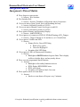
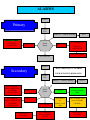
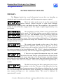
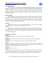
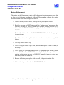
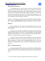
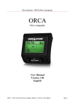
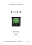
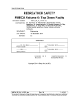
Juergensen Marine HammerHead Electronics User Manual Revision 2.03 Copyright ©2008, Joseph A. Radomski All Rights Reserved Table of Contents ABOUT THIS MANUAL .......................................................................... 1 INTRODUCTION ...................................................................................... 2 SETUP and INSTALLATION .................................................................. 2 Important Oxygen Sensor information..................................................................................... 2 Important Battery Information ................................................................................................. 4 Primary Handset............................................................................................................................ 6 Secondary Handset........................................................................................................................ 7 System Overview ........................................................................................ 8 Set-Point Switching ..................................................................................................................... 9 Juergensen’s Threat Matrix..................................................................................................... 10 HANDSET DISPLAY DETAILS ........................................................... 12 PRIMARY: ................................................................................................................................ 12 SECONDARY: .......................................................................................................................... 13 Handset Overview .................................................................................... 15 Set-Point Operation .................................................................................................................. 15 PRIMARY Handset Options and Programming .................................. 16 SELECTING DILUENT/ OC GAS......................................................................................... 16 DILUENT LOOP FLUSH........................................................................................................ 16 SELECTING CC / OC ............................................................................................................. 16 OPTION MENU........................................................................................................................ 17 SECONDARY Handset Options and Programming ............................ 26 STACK TIME OPT .................................................................................................................. 26 VIEW STACK TIME ............................................................................................................... 26 SET STACK TIME................................................................................................................... 26 DECOMPRESS MODE ........................................................................................................... 27 DISPLAY OPTIONS ................................................................................................................ 28 SET DIVA MODE .................................................................................................................... 28 When Things Go Wrong.......................................................................... 30 Depth Sensor Failure: ............................................................................................................... 30 Wet-switch Failure: .................................................................................................................. 31 Battery Failure: ......................................................................................................................... 31 Oxygen Sensor Failures:........................................................................................................... 31 MAINTENANCE: .................................................................................... 32 Battery Replacement: ............................................................................................................... 32 Banana Block and Harness: ..................................................................................................... 33 Handsets: ................................................................................................................................... 33 DIVA / Lumberg Connectors: ................................................................................................. 33 About Oxygen Sensors ............................................................................. 34 © Joseph A. Radomski (modification is strictly prohibited without written consent) I Tables and Illustrations Table 1: 3.6 Volt Lithium Battery Comparison ................................................................................. 5 Illustration 1: Primary Handset Flowchart............................................................................................ 6 Illustration 2: Secondary Handset Flowchart........................................................................................ 7 Illustration 3: Alarm Flowchart .......................................................................................................... 11 © Joseph A. Radomski (modification is strictly prohibited without written consent) II HammerHead Electronics User Manual Juergensen Marine ABOUT THIS MANUAL There are several revisions of the HammerHead Electronics, Rev A, Rev B, Rev C, Rev C with a digital pressure transducer, and Rev C+. The first three hardware revisions were in the acrylic handsets. The aluminum handsets used modified Rev C hardware that added a digital pressure transducer. The Delrin handsets use Rev C+ hardware that adds battery voltage monitoring capabilities. This manual specifically addresses Primary version 8.07 and Secondary version 6.07. references to maintenance and O-ring sizes are specific to the Delrin handsets. All The software in V7.07 Primary is a subset of the V8.07 software. The V7.07 software lacks the ability to calibrate at altitude, to monitor and warn about battery condition, and uses a different button to confirm calibration. The software in the V5.05 Secondary lacks the ability to calibrate at altitude, to monitor and warn about battery condition, uses a different button to confirm calibration, and lacks the optional decompression. Primary software V7.07 corrects the Oxygen injection at reboot condition present in the V7.06 software. Updating to the current software is recommended. REVISIONS: Feb 11, 2008 – Initial Release Feb 12, 2008 – Fixed Typos, Updated System Failures, added solenoid info Feb 13, 2008 – Added info on Test Stack March 6, 2008 – added battery voltage display info © Joseph A. Radomski (modification is strictly prohibited without written consent) 1 HammerHead Electronics User Manual Juergensen Marine INTRODUCTION The HammerHead electronic package consists of two handsets called the primary and secondary, and the DIVA Heads-Up display. The primary is responsible for maintaining the selected set-point, displaying the measured PO2 for the three main oxygen sensors, time, depth and decompression information. The secondary is a backup display for the main Oxygen sensors, secondary depth gauge, timer, DIVA Heads-Up display controller and OPTIONAL decompression information. The secondary DOES NOT CONTROL the solenoid, it is meant to allow the diver to manually maintain the breathing loop in the event of a primary failure. The only common point between the primary and secondary is the oxygen sensors. Each handset is fully independent and does not communicate with the other in any way. All set-point changes and calibration must be independently performed. SETUP and INSTALLATION The HammerHead electronics allow the user to heavily customize the system to their diving preferences. It is recommended to initially configure a few basic settings and customize the system over time. The initial system set up in as follows: 1) Install Oxygen Cells 2) Install Batteries 3) Enter Activation, and other optional PINS (see Password Manager) 4) Turn Decompress Mode ON (Secondary Only – enabled by PIN) 5) Enter User Gases – Primary (Secondary – enabled by PIN) 6) Select an Initial Gas – Primary (Secondary – enabled by PIN) 7) Set Conservatism – Primary (Secondary – enabled by PIN) 8) Set Solenoid Mode (Primary Only) 9) Set Battery Warning 10) Set Units (Imperial/Metric) 11) Set Stack Timer (Secondary Only) 12) Set Display mode (Secondary Only) 13) Set DIVA mode (Secondary Only) 14) Initial Calibration Important Oxygen Sensor information The HammerHead can operate with any Oxygen sensor designed for hyperbaric applications that has a minimum of approximately 8.4 mV in air at sea level and a suggested maximum of 13.0 mV in air at sea level. The standard cell harness is designed to connect to cells using a Molex connector. Some suitable cells are Teledyne R22d, Analytical Industries PSR-11-39-MD and PSR-11-29-MHD. © Joseph A. Radomski (modification is strictly prohibited without written consent) 2 HammerHead Electronics User Manual Juergensen Marine The HammerHead allows for the tracking of sensor health by allowing the user to display millivolt readings for each sensor. This is accomplished by utilizing the “MV DISPLAY” option located under the “OPT” menu on both the primary and secondary handsets once the harness is connected. A log to help determine sensor health should be maintained with the following information: cell installation date, serial number, cell position, millivolt readings (air and oxygen), oxygen percentage of calibration gas, date, time, and barometric pressure. This data can be used to expose cells that are aging and going nonlinear for PO2 readings of 0.21 to 1.00. Good performance within this region DOES NOT GUARANTEE the cell will perform correctly above this region. For further information refer to the section dealing with handset calibration. © Joseph A. Radomski (modification is strictly prohibited without written consent) 3 HammerHead Electronics User Manual Juergensen Marine Important Battery Information The HammerHead, like many modern dive computers is never really “off”. When the handset is in low power (sleep) mode there is very little current drain and the batteries can remain inserted under normal conditions, but the unit must, by necessity, “wake up” every second to scan the Wet Sensor and both Push Buttons to see if either has been activated. Batteries should not be left installed during an extended period of inactivity (more than a few days). Fresh batteries should be installed prior the next use. Battery removal will normally clear all tissue data, set the gas to MIX 1, and if in CCR mode set the PO2 to 0.7ata. NO other settings are altered. User defined settings such as custom gas mixes, conservatism, imperial or metric units, and CCR/OC are unchanged. The batteries can be changed without loss of data by utilizing the “Go to Sleep” function and quickly replacing the cell(s). It is very important to avoid touching the wet switch and the buttons while the battery is removed. Any of these conditions will take the unit out of sleep mode and all tissue loading data will be lost. The “Go to Sleep” function is NOT the same as the unit automatically shutting down. The HammerHead electronics have been designed to operate over a wide voltage range from a single 1.5v size AA alkaline/Lithium batteries to dual 3.6v size ½ AA batteries. Alkaline batteries are inexpensive and readily available worldwide, while Lithium 1.5v batteries exhibit good performance with high drain devices over a wide temperature range but with a different failure mode from most other batteries. As most cells begin to fail, the voltage or current supply drops gradually, allowing many devices to continue to operate with some limitations. This is not the case with Lithium 1.5v Cells. A word of Caution: Battery alarms with lithium 1.5v cells will give very little warning of imminent failure because the cells maintain a fairly constant voltage right up until the end of its useful life. The MAXIMUM operating duration based on a single Energizer Alkaline size AA battery is 12 hours under ideal conditions. These recommendations are estimates based on fresh batteries with average solenoid firing rates and normal backlight activations. Excessive use of the backlight or low ambient temperature will reduce battery life. Low temperatures typically reduce a battery’s voltage overall duration by at least 50%. Juergensen Marine recommends a maximum battery change interval of 6 hours and a preferred interval of 3 hours for standard alkaline batteries. In water with temperatures near freezing, the use of 1.5v lithium or 3.6v lithium cells should be strongly considered. There have been several reports of system reboots on the Primary using alkaline cells as early as 90 minutes when used in near freezing conditions coupled with high solenoid activity. Increased battery duration can be realized with the use of the proper 3.6v lithium batteries. Not all cells are created equal, just because two cells say 3.6v does not mean they have the same operating characteristics. The author has tested and researched the many of the common batteries available; see the chart on the following page. © Joseph A. Radomski (modification is strictly prohibited without written consent) 4 3.6 Volt Lithium Battery Comparison Brand SAFT Tadiran Xeno Energy Size Model Stated Capacity Rating under load 500mAH @40mA, ~900mAH @16mA 200mAH @40mA, ~600mAH @16mA 1.6 AH @40ma, ~2.1AH @16mA, 1.9AH @25mA < 0.6AH @40ma, ~2.2AH @16mA, 1.4AH @25mA .7AH @3mA,rated for 50mA Max 1/2 AA LS-14250 950 mAH 1/2 AA LS-14250C 1200 mAH AA LS-14500 2250 mAH AA LS-14500C 2700 mAH 1/2 AA TL-2150 1000 mAH 1/2 AA TL-5101 950 mAH 1/2 AA TL-5902 1100 mAH AA TL-2100 2100 mAH rated for 2ma max! 600mAH @20mA,rated for 50mA Max ~1.6AH @16mA, rated for 120ma Max AA TL-96311 1200 mAH 800mAH @2ma AA TL-5104 2100mAH rated for 2ma max! AA TL-1550HP AA TL-5903 2400 mAH 1/2 AA XL-050F 1200mAH AA XL-060F 2400 mAH 550mAH @1A 550mA @ 100mA ~1.7AH @31mA, rated for 200ma Max .4AH @ 30 mA, .5AH @ 20mA, .8AH @ 10 mA, ~1.8AH @16mA, rated for 100ma Max Cont. Comments Recommended VERY Short Life in Primary, Secondary use with CAUTION Recommended VERY Short Life in Primary, Secondary use with CAUTION Unknown Duration use with CAUTION designed for Memory Backup NOT Recommended Marginal on Primary, Secondary use with CAUTION Acceptable designed for Pulse Applications Duration Not Known designed for Memory Backup NOT Recommended NOT Recommended by battery manufacturer Recommended Marginal on Primary, Secondary use with CAUTION Acceptable WARNING! When changing the PRIMARY (or SECONDARY with Deco enabled) handset’s battery, the correct replacement procedures must be followed to prevent the loss of tissue-loading data. This process is detailed in the maintenance section of the manual. In the event the data is reset, The HammerHead should not be used to calculate decompression requirements for a period of no less than 24 hours otherwise the risk of DCI is substantially increased. Normal display Primary Handset Set-Point #1 Set-Point #2 Set-Point #3 Set-Point #4 Factory Use Only User Entry WARNING! WARNING! GF Factors EMERGENCY USE ONLY! User Defined GF Factors Set-Point #5 GAS User Defined Values 1 2 3 4 5 6 7 8 9 10 FO2 OC CLOSED CIRCUIT OPT DEFINE GAS CONSERVATISM OPEN CIRCUIT 1 2 3 4 5 10 9 8 7 6 1 2 CUSTOM GRADIENT DEFINE SET POINT 3 GF-HI 1 4 5 6 GF LOW 2 3 4 5 CALIBRATE O2 BACKLIGHT TIMER 2 – 30 Seconds BATTERY WARNING 1.2 – 7.0 Volts IMPERIAL--METRIC IMPERIAL SOLENOID FIRING AUTO SHUTDN RATE JUERGENSEN METRIC OFF STANDARD 2 to 30 minutes MV DISPLAY BAROMETER OFF STANDARD ERROR 1% to 10% PASSWD MANAGER USER EN PSSWD ERASE ALL PASSWD GO TO SLEEP EXIT MENU He EN PSSWD EXIT MENU BS-O-METER DIAGNOSTIC PSWD ABOUT ON Normal display Secondary Handset Set-Point #1 Set-Point #2 User Defined Values Set-Point #3 User Entry Set-Point #4 Factory Use Only WARNING! WARNING! Set-Point #5 OPT ENABLED BY PIN DEFINE SET POINT DEFINE GAS CONSERVATISM CUSTOM GRADIENT 1 2 3 4 5 1 2 3 4 5 10 9 8 7 6 1 2 3 4 GF-HI 5 6 GF LOW CALIBRATE O2 STACK TIME OPT VIEW SET RESET TEST BACKLIGHT TIMER 2 – 30 Seconds BATTERY WARNING 1.2 – 7.0 Volts IMPERIAL--METRIC IMPERIAL AUTO SHUTDN RATE 2 to 30 minutes DECOMPRESS MODE OFF DISPLAY OPTIONS DEPTH / TIMER METRIC ON DEPTH / TIMER / STACK CLASSIC MV DISPLAY DISPLAY DECO BAROMETER OFF ON SET DIVA MODE USER SETPOINT PPO2 MODE PASSWD MANAGER USER EN PSSWD ERASE ALL PASSWD EXIT MENU DECO EN PSSWD EXIT MENU BS-O-METER DIAGNOSTIC PSWD ABOUT OFF ON HammerHead Electronics User Manual Juergensen Marine System Overview Before being able to dive the unit, it is necessary to understand the conventions used by the handsets, calibrate the oxygen sensors and set diver preferences. Initially out of the factory, some common set-points are defined, all gas mixes are programmed to AIR, and the units are set to imperial. The handsets need activation before they will operate. This is done by the entry of a PIN which can only be obtained for a specific unit from the manufacturer through a certified instructor. The primary handset requires one PIN to enable the handset and another to enable helium based decompression. The secondary requires one PIN to activate the handset and has an optional PIN to enable deco functionality. Activation PINS: Primary: Serial Number: __________ User: _________ Helium: _________ Secondary: Serial Number: __________ User: _________ Deco: _________ The primary handset can operate using Imperial or Metric units of depth and temperature but the PO2 on both handsets is ALWAYS displayed in units of ATA not Bar. This should be of particular interest because several other CCRs and dive computers use Bar as base unit. The use ATA as the base unit conforms to NOAA exposure definitions. The European tradition of using NOAA exposure tables but treating the values, in units of Bar is slightly more conservative for oxygen exposures. Planning the dive with the set-point in Bar while set-point is actually in ATA will result in a slightly more conservative profile. The HammerHead electronics are unique in several ways, the key areas being setpoint switching and set-point maintenance. There are CCRs that have automatic set-point switching and set-point maintenance, manual set-point switching with automatic set-point maintenance, and fully manual control. The HammerHead electronics offer all of these options to the diver and can be changed at anytime. Closed circuit rebreather divers typically use more than a one set-point during a dive. Manufacturers have supported this in several ways, based on the designer’s philosophy. Some have taken the standpoint that the user can not be relied upon to switch set-points at the proper time and the electronics should do it automatically. This typically involves using two PO2 settings chosen by the diver and switch point chosen by the manufacturer. Once the chosen depth has been reached the controller automatically adopts the appropriate set-point. Other manufacturers have taken the stance that the diver should have full control of all set-point switching. This standpoint places the responsibility for all set-point switches squarely on the diver. Lastly, there are fully manual rebreathers which have no set-point maintenance. The diver is responsible for the composition. The first case is probably best for the new CCR diver, while manual set-point switches are probably the mode of choice for the experienced diver. Fully manual rebreathers are not recommended. The HammerHead supports all of the above modes. © Joseph A. Radomski (modification is strictly prohibited without written consent) 8 HammerHead Electronics User Manual Juergensen Marine The manual mode (Solenoid Control OFF) is designed for emergency use only and should not be used under normal circumstances. The most likely scenario for using this mode is that TWO sensors are reading low while a single system sensor is reading correctly. This would cause the voting logic to inject too much oxygen based on the faulty sensors. This mode has a built in safety override, the system will fire the solenoid if the calculated average PO2 is 0.19 or less. Set-Point Switching The HammerHead determines manual or automatic set-point switching based on the selected Set-point. Manual mode is selected on the surface by choosing any set-point 1.0 ATA or less. If the diver chooses a set-point greater than 1.0 ATA, the electronics will start the dive with a set-point of 0.4 ATA, transition to 1.0 ATA at 1m (~3fsw), and finally the chosen set-point at 3m (10fsw). Automatic set-point switching is performed (in reverse) on ascent if the selected set-point is greater than 1.0 ATA and the depth is less than 3m (10fsw). Each manufacturer comes up with their own unique formula to determine when oxygen is to be injected; the user generally has no control over this function. The HammerHead has two user selectable modes, standard mode, which allows a user defined deviation below set-point before the solenoid will fire, and Juergensen mode which adapts to depth and distance from set-point to determine firing duration and frequency. For most users the preferred method is Juergensen mode which maintains a highly stable set-point with little to no overshoot at depth. Each handset has two buttons, which are used for programming and control. Pressing either button will activate the backlight for the user chosen time, and will wake up a handset that is in sleep mode. The left button scrolls through menu selections and values while the right button selects the current value. The handsets will timeout after a 10 second period of inactivity, and return to the normal operation mode. Several options will require confirmation. Failure to confirm action cancels any changes. The handset Backlight and LEDs also serve as a CRITICAL ALARM. This alarm is disabled on the primary while operating in open circuit mode The design goal of the HammerHead electronics was to make the safest CCR controller in the industry. All reasonable attempts have been made to prevent a single failure from becoming a life-threatening occurrence. When the electronics were being designed, Kevin Juergensen sketched out what he called a “Threat Matrix”, listing possible conditions along with generated warnings and solutions. © Joseph A. Radomski (modification is strictly prohibited without written consent) 9 HammerHead Electronics User Manual Juergensen Marine Juergensen’s Threat Matrix Diver forgets to turn on unit: ¾ Answer: Wet Switches Wet Switches Fail: ¾ Answer: Pressure Transducer will activate unit at 1m pressure Diver sets unit to Open Circuit, but is still breathing the loop. ¾ Answer: Solenoid Override at 0.19 PO2 Diver sets unit to Manual Control, but forgets to add O2: ¾ Answer: Solenoid Override at 0.19 PO2 Diver ignores Primary and Secondary Display: ¾ Answer: Add HUD/DIVA Diver ignores or is unaware of DIVA LED Red Warning of PO2 Danger: ¾ Answer: Trigger Vibrator at 1.8 and above, or 0.19 and below. Diver ignores Vibrator and LED: ¾ Answer: Primary Red or Green LED firing • Red for Low ppO2 • Green for High ppO2 Secondary Red LED firing Diver ignores LED's in Primary and Secondary: ¾ Answer: Backlights in BOTH handsets begin to flash. This is highly visible to both the diver, and any nearby divers. Diver exceeds programmed Stack Duration: ¾ Answer: Backlight on Secondary handsets turns on. DIVA flashes RED/GREEN twice. DIVA will vibrate Secondary will indicate Stack Over-run. Diver ignores stack over-run alarm. ¾ Answer: Stack over-run alarm will repeat every 2 minutes. © Joseph A. Radomski (modification is strictly prohibited without written consent) 10 ALARMS START Primary READ PO2 Battery V < Battery Warning BAT Green Flashing LED FLASHING BACKLIGHT PO2 >= 1.8 Check Status Red Flashing LED PO2 <=.19 FLASHING BACKLIGHT FIRE SOLENOID SYSTEM OK START DIVA Visual STATUS / ALARMS Secondary USER SET-POINT MODE ONLY! READ PO2 Battery V < Battery Warning <PO2! ERROR!> DIVA VIBRATING FLASHING BACKLIGHT <PO2! ERROR!> DIVA VIBRATING FLASHING BACKLIGHT PO2 >= 1.8 Check Status PO2 <=.19 RED LED on Secondary 25% and Up DIVA Red LED Every 2 seconds ALERT < 15% 15% to 24% or Sensor Voted Out <BAT> DIVA Green LED Every 8 seconds <OK> DIVA Orange LED every 5 seconds <WARN> RED LED on Secondary HammerHead Electronics User Manual Juergensen Marine HANDSET DISPLAY DETAILS PRIMARY: The Primary handset has several informational screens that vary depending on whether the unit is in surface or dive mode, and if decompression stops are required. This is the surface mode screen; the top line consists of the surface interval, selected set-point or open circuit indicator, maximum depth of previous dive, and finally dive time. The second line is the current PO2 reading for each of the three oxygen sensors. The display is updated approximately every two seconds. 1:38 OC 008 000 0.73 0.73 0.71 The next display is the first of three screens presented while in dive mode. The first line displays current depth, selected setpoint, dive time and alternates between maximum depth and 031 1.0 0:00 3.2 1.11 1.11 1.10 measured battery voltage or battery alarm. The second line displays the PO2 readings of the three sensors. If any sensor reading is followed by a “*” that sensor has been voted out and is not used in the average PO2 calculation. This screen is displayed for approximately 2 seconds. 031 1.0 0:00 031 1.11 1.11 1.10 The second screen depends on the status of the diver’s decompression obligation. The top line is the same as on the previous screen with the change being on the second line. Instead of the PO2 being displayed, the oxygen percentage of the selected diluent and “No Stop” is displayed until the diver enters a required decompression stop. This screen is displayed for approximately 2 seconds. 033 0.7 0:00 034 21% NO STOP If there are any required decompression stops, the second screen have the same first line as the previous two screens, but the second line now displays the oxygen percentage of the diluent, deepest stop depth and stop time followed by the total ascent time. The sample screen shows the deepest stop at 20fsw for two minutes and a TTS of 12 minutes. This screen is displayed for approximately 2 seconds. 170 1.0 0:12 172 21% 2@ 20 12 The third screen may seem like an annoyance, but it serves as a reminder to the diver. The name of the diluent the diver has selected and the programmed oxygen percentage of the diluent are displayed on the second line. This should help insure that the diver doesn’t accidentally use a nitrogen only mix with same oxygen percentage as a mix containing helium. This screen is displayed for approximately 2 seconds. 032 0.7 0:00 034 Air 21% © Joseph A. Radomski (modification is strictly prohibited without written consent) 12 HammerHead Electronics User Manual Juergensen Marine SECONDARY: The Secondary handset has three possible display options (“Classic” - Classic, “D/Timer” - Depth/Timer, and “D/TandS” - Depth/Timer/Stack Timer). Classic Mode This mode displays system status, warnings and PO2 on a single screen. All warnings and alarms are based on the deviation from the target set-point. The secondary must be set to the desired set-point in the same manner as the primary. The top line of the display shows the system status or the battery status / voltage (<OK>, <WARN>, ALERT, PO2! ERROR!, or <BAT>). This is followed by the calculated average PO2, and the selected set-point. The second line displays the PO2 measurements for each sensor. If any sensor reading is followed by a “*” that sensor has been voted out and is not used in the average PO2 calculation. All sensors that fail calibration (less than 40mV in 100% oxygen) will be disabled until successfully calibrating; the disabled cells will show FAIL and not be used in any calculation. <OK> 1.00 1.0 1.00 1.0 1.00 <WARN> 0.8 1.1* 0.86 0.7 0.81 ALERT 1.0 1.2* 0.96 0.7 0.99 PO2! ERROR 0.1* 0.0* 0.0 FAIL The voting logic used in both the primary and secondary handsets is identical. Any sensor that is 15% out of range from the average of the remaining two sensors will be voted out. The three screenshots above show sensor one voted out. The second screenshot shows system status of <WARN>, this is indicated if any sensor is voted out or the average PO2 is at least 15% from selected set-point. The next screen shot shows an error of at least 25%, so ALERT is indicated. The last screen shows a status that no diver wishes to see, PO2 ERROR, this will be indicated if the average PO2 reaches 1.8 or is 0.19 and below, the RED LED and the backlight are illuminated. <BAT> 1.0 1.00 1.00 1.0 1.00 <3.0> 1.0 1.00 1.00 1.0 1.00 Depth/Timer Mode This mode cycles between THREE different screens. The PO2 for all cells is displayed on the second line of all screens. The first screen is identical to classic mode and is the main status screen. The second screen displays current depth, Temperature and maximum depth. The third screen displays the current depth and the total dive time in the format hours:minutes:seconds. <WARN>0.8 1.1* 0.86 0.7 0.81 25.6 68F > 28.6 1.00 1.00 1.00 24.0 T :22:40 1.00 1.00 1.00 © Joseph A. Radomski (modification is strictly prohibited without written consent) 13 HammerHead Electronics User Manual Juergensen Marine Depth/Timer/Stack Mode This mode cycles between FOUR different screens. The PO2 for all cells is displayed on the second line of all screens. The first three screens are the same as in Depth/Timer mode. The fourth and final screen displays the remaining stack time. The stack time display is simply a countdown timer based on a user programmed limit. This timer counts once the diver submerges. An alarm will be generated once this time is exceeded and the remaining stack time will now show a negative time. Stk Left 129 Min 1.00 1.00 1.00 Stk Left -13 Min 1.00 1.00 1.00 Display of Deco Information When the secondary deco is enabled and the deco display is enabled, the PO2 information on the second line on the display will replaced with decompression information. Depth/Timer mode displays the deco information after the depth and time screens and in Depth/Timer/Stack mode; the information is displayed after the depth and time but before the stack time data. The first “deco” screen depends on the status of the diver’s <OK> 1.0 1.0 decompression obligation. The top line is the standard status screen 21% NO STOP with the change being on the second line. Instead of the PO2 being displayed, the oxygen percentage of the selected diluent and “No Stop” is displayed until the diver enters a required decompression stop. This screen is displayed for approximately 2 seconds. If there are any required decompression stops, the next screen will have the standard status line, but the second line now displays the oxygen percentage of the diluent, deepest stop depth and stop time followed by the total ascent time. The sample screen shows the deepest stop at 20fsw for two minutes and a TTS of 12 minutes. This screen is displayed for approximately 2 seconds. <OK> 1.0 21% 2@ 20 1.0 12 The final screen may seem like an annoyance, but it serves as a reminder to the diver. The name of the diluent the diver has selected and the programmed oxygen percentage of the diluent are displayed on the second line. This should help insure that the diver doesn’t accidentally use a nitrogen only mix with same oxygen percentage as a mix containing helium. This screen is displayed for approximately 2 seconds. <OK> Air 1.0 1.0 21% © Joseph A. Radomski (modification is strictly prohibited without written consent) 14 HammerHead Electronics User Manual Juergensen Marine STACK OVERRUN ALARM – ALL MODES Once the programmed max stack time is exceeded, the secondary will turn on the backlight for 5 seconds, indicate STACK OVERRUN on the display, flash the DIVA Red/Green, Red/Green, and operate the buzzer in the DIVA twice. This alarm will recycle every TWO MINUTES until it is cleared by reprogramming the max stack time to a greater value. STACK OVERRUN 1.02 1.00 1.01 Handset Overview The options available in the primary handset are grouped into two main “menus”. The first grouping contains the functions most likely to be used during a dive, while the second grouping under the options menu ”OPT” is used to gain access to additional functions including handset configuration. For safety reasons several functions in the second grouping are unavailable while in dive mode. The secondary handset has a similar arrangement, where the first grouping scrolls through the user set-points, and the second grouping under the options menu ”OPT” is the configuration functions. For safety reasons several functions in the second grouping are unavailable while in dive mode. Set-Point Operation One of the main features of the HammerHead is the ability for the diver to select a new set-point based on a user programmed set of five choices. The HammerHead comes preprogrammed with set-points of 0.4, 0.7, 1.0, 1.2, and 1.4. Regardless of the current operating set-point pressing the left button will cycle through the set-point choices in sequence. Once the desired set-point is displayed it is selected by pressing the right button and confirming once prompted with the left button. 1:38 0.4 008 000 0.73 0.73 0.73 1:38 0.7 008 000 0.73 0.73 0.73 1:39 1.2 008 000 0.73 0.73 0.73 1:39 1.0 008 000 0.73 0.73 0.73 1:39 1.4 008 000 0.73 0.73 0.73 © Joseph A. Radomski (modification is strictly prohibited without written consent) 15 HammerHead Electronics User Manual Juergensen Marine PRIMARY Handset Options and Programming The additional functions in both the primary and secondary are accessed by scrolling past the set-point selections using the left button. SELECTING DILUENT/ OC GAS On the primary, the first option available is the gas selection prompt. Pressing the right button will select this function. Each press of the left button scrolls to the next programmed gas mix until Air 21/ 0 NEXT SELECT all 10 are displayed, eventually returning to first mix. Once the desired mix is displayed, pressing the right button will select it. The diver will then be prompted to confirm or cancel the mix change. Pressing the left button confirms the selection, while the right button or no action for 10 seconds cancels the switch. GAS NEXT SELECT DILUENT LOOP FLUSH FO2 NEXT SELECT Diluent ppO2 is: 0.22 The next selection is the FO2 display screen. Pressing the right button will immediately display the calculated PO2 for the current diluent and current depth. A proper loop flush with diluent should result in this value. SELECTING CC / OC OC NEXT SELECT The next option allows the diver to put the handset in either open circuit or close circuit mode. In open circuit mode, solenoid control is disabled, unless the PO2 falls to 0.19Ata. This function allows the diver to bail onto open circuit and still have decompression obligations calculated. Switching to open circuit OC Closed Circuit mode also prevents the display from flashing while the system is being worked on, or disconnected from the rest of the rebreather. The left button toggles between modes while the right button selects the displayed mode. The system has a short cut out of open circuit and into closed circuit. If the diver chooses a set-point while the handset is operating in open circuit, the handset immediately switches to closed circuit mode with the selected set-point. OC Open Circuit © Joseph A. Radomski (modification is strictly prohibited without written consent) 16 HammerHead Electronics User Manual Juergensen Marine OPTION MENU The next set of options is entered through the “OPT” menu. Selecting this screen enters a sub-menu containing programming, calibration, and testing options. Some of these selections will be locked out for safety once the handset enters dive mode. OPT NEXT SELECT DEFINE GAS The first function under the “OPT” menu is the “Define Gas” option; this allows the diver to program up to ten custom mixes. These gases can be any nitrogen-oxygen, heliumoxygen, oxygen, or tri-mix. Each gas can have a user-selected name consisting of 6 characters and should be named to allow easy identification. Define Gas NEXT SELECT Gas Mix 1 NEXT SELECT Air NEXT SELECT Once the “Define Gas” screen is displayed, the diver must press the right button to select. The next prompt is “Gas Mix 1”; continue pressing the left button until the mix to be programmed is displayed. The right button will enter the gas-naming screen. Choose any name up to six characters; the current character will be displayed with the character underlined. The left button will cycle through available characters while the right button proceeds to the next character. After all six characters have been entered; entry of the gas composition will be prompted, starting with the oxygen percentage followed by the helium percentage. The remainder will be assumed nitrogen. For oxygen, enter an oxygen percentage of 99%. © Joseph A. Radomski (modification is strictly prohibited without written consent) 17 HammerHead Electronics User Manual Juergensen Marine CONSERVATISM The next option is setting the level of conservatism for the decompression model. Upon selecting the Conservatism function the current Gradient Factors are displayed. The HammerHead is a true gradient factors implementation with separate limits determining where the stops begin and when to proceed to the next level. There are five preprogrammed gradient factor sets and one user programmable setting. The selected gradient factor can be changed during the dive allowing full control over the dive profile. The user programmable selection can even be reprogrammed while in dive mode. Changing the conservatism requires entering the “OPT” menu by scrolling past the set-point changes and other miscellaneous functions until “OPT” is displayed. Enter this menu by pressing the RIGHT button. Press the left button until “Conservatism” is displayed, press the RIGHT button to select. The current conservatism will be displayed. GF Now NEXT [10/100] SELECT The user can now scroll through the 6 programmed settings with the LEFT button. Each choice will display the associated GF-Low and GF-High settings. GF [1] NEXT [10/100] SELECT GF [2] NEXT [20/95 ] SELECT GF [3] NEXT [25/85 ] SELECT GF [4] NEXT [30/75 ] SELECT GF [5] NEXT [35/70 ] SELECT GF User [95/100] NEXT SELECT Once the desired setting is displayed, select it with the RIGHT button then confirm the choice when prompted with the LEFT button. All confirmations on the HammerHead are done using the LEFT button. This prevents accidental confirmations due to double button presses. For a complete Gradient Factor explanation see Erik Baker’s paper on Deep Stops available at ftp.decompression.org plus many other decompression software sites. © Joseph A. Radomski (modification is strictly prohibited without written consent) 18 HammerHead Electronics User Manual Juergensen Marine What Are Gradient Factors? Gradient factors are modifiers used to control the shape of the decompression profile in a consistent manner. There are two parameters GF-Low and GF-High. The first parameter sets the tissue loading limit used to determine the initial stop, while the second parameter sets the maximal allowable tissue loading upon surfacing. The difference between the calculated first stop and surface determine the slope used to modify the “M-values” during the ascent. For each given depth the “M-value” is lowered based on the computed GF for that depth. For example if the GF settings are 10/95, the diver is allowed to ascend until the tissue loading is 10% of the controlling compartment, at each successive stop depth, the maximal tissue loading is increased based on the calculated slope until the GF-High is reached at the surface. This means the GF-High parameter determines the overall level of conservatism by setting the final surfacing compartment tension limits. The lower the GFLow setting is, the deeper the first stop will be and the lower the GF-High setting is, the longer the overal decompresssion will be. A unique ability of the HammerHead decompression software is allowing the diver to change conservatism levels while underwater. This has some potential benefits as well as potential downsides. If the diver plans on using the ability to change conservatism while underwater , the diver should start with the most conservative setting expected, and lower the level of conservatism, conditions permitting. Higher levels of conservatism and/or lower GF-Low will generall result in deeper initial stops. It is not recommended going from a higher GF-Low value to a lower value while underwater unless you are still below the expected stop depth of the new setting. Changing the conservatism with a GF-Low setting lower than the current setting might require a stop deeper than the current depth. The diver must now decide whether to descend or stay at current level until the tissue loading offgasses to the new limits. The best alternative is to program a custom conservatism setting with the same GF-Low setting and a new less conservative GF-High setting. The first predefined conservatism setting [10/100] is very aggressive, has deep initial stops, and a surfacing compartment gradient equal to Buhlman’s limits. This setting is primarily designed for individuals in good physical fitness with good control over ascent rates and stop depths. The second setting [20/95] stages the initial stop shallower but backs off allowable surfacing limits The third setting [25/85] is applicable to most divers with light workloads and warm water. The fourth setting [30/75] covers most divers with moderate work loads for a wide variety of water temperatures. The last predefined [35/70] value is ultra conservative with the lowest allowable tissue tensions. This setting has the shallowest of the initial stops and longest stop times. The final setting defaults to [36/71] in order to initialize the user setting and should be redefined to some suitable values. The HammerHead enforces a limit that the GF-Low setting must be at least 5% less than the GF-High value. In practice, this limitation should force a stop depth (when required) one level deeper than the maximal allowable tissue loading. © Joseph A. Radomski (modification is strictly prohibited without written consent) 19 HammerHead Electronics User Manual Juergensen Marine Creating and using custom gradient factors should only be undertaken by those that understand the consequences of these settings. The limits imposed by the “Custom GF” entry insure that the entered values should not be less conservative in theory than an unmodified Buhlman profile. The use of an aggressive level of conservatism should not be undertaken lightly, the risk of decompression sickness is real. It is never recommended to dive any computer to the maximal limits. The conservatism settings of 3 and 4 are a good balance between potential risk and decompression obligation. NO conservatism setting or decompression plan can guarantee ZERO risk of decompression sickness! CUSTOM GRADIENT The next option allows the entry of the custom gradient discussed in the previous section. The first value entered is the GFHigh, followed by the GF-Low setting. This is necessary to allow setting the upper limit for the GF-Low setting 5% below the GF-High value. Custom Gradient NEXT SELECT Custom Gradient Gf Hi = [100] Custom Gradient Gf Lo = [ 95] DEFINE SET-POINT Define Set Point NEXT SELECT This option allows the defining of five user selectable setpoints. After choosing the “Define Set Point” option, the handset will begin prompting with “Set Point 1” the left Setpoint 1 Setpoint 1=[0.4] button will scroll to the next set-point while the right button enters the programming for the displayed set-point. The left button is used to modify the value of the chosen set-point. This starts with the current setting, incrementing to a maximum of 1.6 and rolling over back to the low value of 0.4. Once the desired value is displayed, the right button is used to accept this setting. The values programmed on the primary should also be programmed on the secondary so that the same set-point can be selected to insure the proper alarms/warnings can be generated. The diver must make it a standard procedure to immediately change the secondary to the chosen setpoint since this is a truly independent DISPLAY and does not communicate with the primary. Alarm generation on the secondary is based on variation from the selected set-point. © Joseph A. Radomski (modification is strictly prohibited without written consent) 20 HammerHead Electronics User Manual Juergensen Marine CALIBRATION Calibrate O2 NEXT SELECT Standard Cal NEXT SELECT Altitude Cal NEXT SELECT Calibrating at 1019 mBar Fill loop w/O2 Cancel Ready Once the calibrate option is selected the next menu is presented that allows the selection of standard calibration (P02 set to 1.00 regardless of ambient pressure), or calibration for altitude which is based on measured ambient pressure. If altitude calibration is selected the measured pressure will be displayed and the PO2 will be set to this value (converted to ATA). The next screen for both modes will show “Fill Loop w/o2”, with prompts for “Cancel” and “Ready“. The calibration techniques used with the HammerHead electronics are the same as many other CCRs. Calibration Sequence: 1) Connect ALL regulators, leave DILUENT Valve off. On systems equipped with an ADV and cut-off valve, make sure the valve is in the off position. 2) Turn on Oxygen and Activate handsets. Make sure that the solenoid fires for several seconds to flush Oxygen through the solenoid. This is easily accomplished by setting the set-point to 1.0 then setting it to a 0.4 once the purge is completed. 3) Evacuate all the gas from the loop, flush with oxygen and repeat at least FOUR times. This is accomplished by inhaling off the loop and exhaling through the nose. The counter-lungs should be bottomed out before adding Oxygen. The hose on the exhale side of the DSV will not be flushed by inhaling only, make sure that you blow Oxygen rich gas around the loop, once or twice (best performed during the second and third flushes) before exhaling out the nose. 4) On final flush add Oxygen until OPV vents gas. 5) Go to the “MV display” screen and take note of the values, exit this screen to prevent the unit from remaining on. 6) Let the unit sit for at least FIVE minutes. Top with oxygen if there is any loss of volume and go to the “MV display” screen again. If the sensor values have decreased, the flush was incomplete so flush again and repeat until readings are stable. 7) Once mV readings are stable, vent excess gas until the loop is at ambient pressure (the BEST way is to force excess gas through the OPV, opening the DSV/BOV risks contamination). 8) Record mV readings (any cell under 40mV will be rejected, the minimum mV will be adjusted for altitude when in altitude calibrate mode)), enter the “Calibrate O2” screen, select the calibration method and select ready. Any sensor that fails to meet minimum mV values will be rejected and the user alerted to the specific cell number. 9) Immediately go to the “Calibrate O2” screen on the secondary, select calibration method and select ready. © Joseph A. Radomski (modification is strictly prohibited without written consent) 21 HammerHead Electronics User Manual Juergensen Marine The typical mV reading for good sensor is between 8.4mV and 13mV in AIR at sea-level and between 40mV and 62mV in 100% Oxygen at sea-level. On systems with a removable sensor plate the above calibration process can be performed by removing the plate (with sensors still connected) and placing it in a plastic bag. This will use considerably less Oxygen and will not require the 5 minute “waiting” period. The HammerHead was designed to be used with 100% oxygen for calibration, using oxygen percentages less than this will cause errors in calibration and depending on how long the loop is left to sit, the measured PO2 and mV readings will drop since Oxygen is being consumed and there is another gas present. The primary and secondary each require calibration. The two handsets are independent! The calibrate option is disabled while in dive mode to prevent a possible accident by the wet switches sensing water or depth sensor detecting a depth. The HammerHead holds a very stable calibration; it is not necessary to constantly recalibrate the handsets. The sensors should be verified to be within a few percent of expected values by performing a quick loop flush with oxygen and/or exposing the sensors to AIR prior to each dive. Although not endorsed by the manufacturer, alternate procedures for calibration can be found in an article published on WWW.REBREATHERWORLD.COM entitled “Accurate PO2 Calibration”. This article discusses hardware, procedures and warnings necessary to calibrate various types of RB electronics using alternate oxygen concentrations and at altitude when not specifically supported by the electronics. © Joseph A. Radomski (modification is strictly prohibited without written consent) 22 HammerHead Electronics User Manual Juergensen Marine BACKLIGHT TIMER Backlight Timer NEXT SELECT Backlight Timer [10] Seconds This option sets the length of time the backlight remains illuminated after pressing either button. The shortest is 2 seconds with a maximum time on period of 30 seconds. The use of the backlight should be kept to a minimum to increase battery life. IMPERIAL / METRIC Imperial--Metric NEXT SELECT Imperial--Metric Imperial Imperial--Metric Metric The Imperial – Metric setting selects system of units that will be used for displaying depth and temperature measurement. The setpoint is always in units of ATA, regardless of the selected system. PO2 by definition is in units of ATA, not Bar which is commonly substituted in non imperial countries. The current selected units will be displayed, pressing the LEFT button will toggle and RIGHT will select. SOLENOID FIRING The solenoid firing function chooses the set-point control algorithm. The modes are scrolled through by use of the LEFT button and selected by the RIGHT button. The HammerHead Solenoid Firing supports two automatic control methods: “Standard Mode” and Juergensen “Juergensen Mode”, plus the non-automatic “Manual Mode”. Solenoid Firing Standard Standard mode uses the error setting from “Standard Error”, while “Juergensen Mode” is an adaptive algorithm that Solenoid Firing Manual(OFF!) changes firing duration and rate based on error from selected setpoint. “Manual Mode” requires the diver to maintain the loop PO2, automatic PO2 control is disabled. This function would be used to override the master when it is suspected that the controller is basing the PO2 control on bad data. An example of this would be two cells agreeing, while a third cell does not agree and the diver determined that the third cell is the correct one. The handset will override the manual setting and fire the solenoid if the loop PO2 drops to a 0.19. Solenoid Firing NEXT SELECT There is no specific recommended Intermediate Pressure setting for the Oxygen first stage. The correct IP is dependent on the solenoid used not the electronics. Sample Settings: Kip Valves (O2ptima) – 6.2bar (90psi) Jaksa - 9.3bar-10.3bar (135psi-150psi) Snaptite (Ideal Setting) - 9.3bar-10.3bar (135psi-150psi) Snaptite (Inspiration LID compatibility) - 7.0bar-7.5bar (100psi-110psi) © Joseph A. Radomski (modification is strictly prohibited without written consent) 23 HammerHead Electronics User Manual Juergensen Marine AUTO SHUTDOWN This option selects the required period of time that must elapse before the handset enters shutdown/low power mode after the last button press water detection by the wet switches. The valid Auto Shutdn Rate settings are two through thirty minutes. A long timeout drains [ 2] Minutes batteries faster, while a shorter timeout saves power. Choose a timeout period that is longer than the maximum expected time required for the diver to enter the water once on the loop. ANY TIME the loop is being used out of the water, care must be exercised. The diver must ensure that the handsets do not enter power saving mode. Once the handset enters shutdown mode, PO2 monitoring and control become inactive. Failure to monitor the handsets may lead to a hypoxic loop and eventual unconsciousness. Auto Shutdn Rate NEXT SELECT MILLIVOLT DISPLAY This option displays the millivolt output for each of the three sensors. While in this mode the backlight remains illuminated and does not timeout. Pressing either button exits the test. This option Sen1 Sen2 Sen3 should be used to record the output of each sensor while in AIR and 39 41 41 100% Oxygen. A log with this information can aid in tracking the cells decay over time. The mV display is also used to diagnose cell problems. Unlike the PO2 display which disables cells that fail calibration, the cells can always be measured. MV Display NEXT SELECT BAROMETER FUNCTION Barometer NEXT SELECT Barometer OFF SELECT Barometer ON SELECT Selecting this function displays the current barometric pressure and temperature. This is useful when verifying calibration or planning dives at altitude. STANDARD ERROR This option sets the allowable error before the solenoid fires in “Standard Mode”. The valid range is from 1% to 10%. A lower value is not necessarily a better setting. In shallow water, a low value will hold a stable set-point with little or no overshooting, but Standard Error [ 5] Percent as depth increases, an overshoot is probable. An error setting of 5% works well over a wide range of depths with acceptable results for most divers. The general rule of thumb is as depth increases; the allowed error should be increased to prevent overshoot. Dive mode does not lock out this option. The diver can change this value at any time. Selecting this option displays the currently programmed value. Each press of the LEFT button will increase the error percentage by 1% until a maximum of 10% error is reached. The next press will cause the error percentage to roll over to the low value of 1%. The RIGHT button selects the displayed setting. Standard Error NEXT SELECT © Joseph A. Radomski (modification is strictly prohibited without written consent) 24 HammerHead Electronics User Manual Juergensen Marine PASSWORD MANAGER Passwrd Manager NEXT SELECT Enter UsrEN PW NEXT SELECT [1234] NEXT SELECT This option allows the user to enable/disable Helium gas usage and to erase all PINs to disable the unit entirely. PINs are supplied to certified users through a student’s instructor. Enter HeEN PW NEXT SELECT [1234] NEXT SELECT Upon the sale of the rebreather/electronics to another party, the handsets should be disabled by clearing all the PINs. The PINs can be reissued through the proper channels once the liability waivers / releases and training has been completed. Erase ALL Passwd NEXT SELECT GO TO SLEEP The option allows the changing of the battery without erasing current surface interval and tissue loading data. Changing the battery without selecting this option will erase all volatile data. Once this option is selected, the display will show “Auto Shutdown”. Do not remove the battery until the display shuts off, the handset is still prepping itself for battery removal. Once the unit shuts down, it is safe to remove the battery. Be careful not to touch the Wet Switch or buttons once the battery is removed. This will activate the unit and erase volatile data. The battery should be changed in a timely manner avoiding any unnecessary delays; consider two minutes as the upper limit. The normal auto shutdown does not allow DATA SAFE changing of the battery. If the unit is already in low power sleep mode, the wrist unit must be activated and manually select “Go to Sleep” GO to SLEEP NEXT SELECT BS-O-METER BS-O-Meter NEXT SELECT BS-O-Meter Mx 199 120:10:00 This option displays the maximum depth and underwater run time attained by the diver. This data is not always cleared by the factory and may have a pressure pot run here. This data is ONLY updated when the unit goes to sleep; if the user removes the battery before the unit goes to sleep the BS-O-METER data will not be updated. © Joseph A. Radomski (modification is strictly prohibited without written consent) 25 HammerHead Electronics User Manual Juergensen Marine ABOUT About NEXT Juergensen Marine 8.07 GB99 SELECT This option displays the copyright, software revision and serial number of the handset. The serial number is needed to obtain the proper unlock PINS. SECONDARY Handset Options and Programming The secondary handset has many of the same options as the primary handset. The notable differences are the lack of functions supporting the deco computer and set-point control options. The secondary has FOUR additional options, “Stack Time Opt” , “Decompress Mode“, “Display Options” and “Set DIVA Mode”. STACK TIME OPT Stack Time Opt NEXT SELECT The stack timer is convenience reminder, and should not be counted on as a life support feature. How useful this option is to the diver is dependent on how faithfully the diver remembers to reset the counter after each scrubber change. The stack timer cannot be disabled, but the user has the freedom to set their own limits and can reset the timer at any time. Selecting “Stack Time Opt” under the “OPT” menu allows the user to scroll through several options relating to the stack timer function. VIEW STACK TIME View Stack Time NEXT SELECT Max Stk Time 180 Used 53 Left 127 The “View Stack Time” option can be used at any time to view the timer limits and how much UNDERWATER time has been put on the scrubber. This is a VERY important concept to remember, time spent on the loop but not at depth is NOT counted towards stack time. Scrubber durations in excess of the limits (stack overrun) will be displayed as a negative time remaining. SET STACK TIME Set Stack Time NEXT SELECT Set Stack Time [_60] Minutes The “Set Stack Time” option allows the user to set the scrubber duration timer in 60 minute intervals ranging from 60 to 600 minutes. Upon entering this function the stack time is set to 60 minutes, the diver now must set the timer limit by using the left button to increment by 60 minutes at a time, with the right button © Joseph A. Radomski (modification is strictly prohibited without written consent) 26 HammerHead Electronics User Manual Juergensen Marine programming the displayed time. WARNING Even if the right button is not pressed, once the programming screen times out, the scrubber limit will be set to whatever is currently displayed as the new limit. Time previously counted as “on the stack” is also reset. This function can be seen as setting the scrubber stack time limit and resetting the counter to the new limit. RESET STACK TIME The “Reset Stack Time” option resets the current stack time to the limit as set in the “Set Stack Time” option. Choosing this option (with the RIGHT button) will prompt the diver to confirm with a LEFT button press. Reset Stack Time NEXT SELECT TEST STACK TIME The purpose of the “Test Stack Time” option is to allow the diver to become familiar with the alarms generated on the secondary display, the flash protocol on the DIVA coupled with the vibrating of the DIVA. This option sets the stack time to one minute, with one minute remaining. This allows the diver to periodically familiarize him/herself with the alarms without having to play with programming the stack time. Once the alarms are confirmed the diver just has to select “Reset Stack Time” and all the previous limits are restored. This option uses the actual stack timer, so this alarm can only be generated while in dive mode. Test Stack Time NEXT SELECT DECOMPRESS MODE The “Decompress mode” function turns the secondary dive computer options on or off. This option is only available when the proper secondary Deco PIN has been entered. Decompress Mode NEXT SELECT Decompress Mode OFF SELECT Decompress Mode ON SELECT © Joseph A. Radomski (modification is strictly prohibited without written consent) 27 HammerHead Electronics User Manual Juergensen Marine DISPLAY OPTIONS The “Display Options” explanation is detailed in the section on display details earlier in the manual. The Three supported display modes are “Classic” (Classic), “D/Timer” (Depth plus Bottom Timer), “D/TandS” (Depth, Bottom Timer plus Stack Timer). Display Options NEXT SELECT Display Options Classic SELECT Display Options D/Timer SELECT Display Options D/TandS SELECT After selecting a display mode and if the “Decompress mode” is enabled, the handset will prompt whether or not the deco information should be displayed. The Left button toggles On/OFF and the right button selects the displayed mode. Display Deco OFF SELECT Display Deco ON SELECT SET DIVA MODE Set DIVA Mode NEXT SELECT This option controls the function of the DIVA/HUD. The two selections are “User Set Point” and “PPO2 Mode”. Once the function is selected the current mode is displayed, the LEFT button toggles the function while the RIGHT button selects the desired mode. Set DIVA Mode PPO2 Mode Set DIVA Mode User Setpoint © Joseph A. Radomski (modification is strictly prohibited without written consent) 28 HammerHead Electronics User Manual Juergensen Marine User Set Point: The secondary uses the 3 available colors within the DIVA to signal alarm conditions. The flash rate and color is dependent on the error percentage from the user selected set-point. ¾ Set-point error is less than 15%; the secondary blinks the DIVA GREEN LED every 8 seconds. ¾ Set-point error is 15% to 24% or a sensor voted out; the secondary blinks the DIVA ORANGE LED every 5 seconds. ¾ Set-point error is 25% or more; the secondary blinks the DIVA RED LED every 2 seconds. PPO2 mode Flash Protocol: The DIVA uses the 3 available colors in the following manner; one RED blink for each 0.1 ata PO2 below 1.0, ORANGE for a PO2 of 1.0 and one GREEN blink each 0.1 ata PO2 above 1.0. The sensor values are rounded to the nearest integer for example 0.75 becomes 0.80, while a 0.74 is rounded to a 0.70. The values for all three sensors are presented in succession with a short pause between sensors. There is an extended Pause (about 3 flash periods) between displaying the sensor #3 and starting again with sensor #1. The duration of the RED and GREEN blinks are the same duration, while the duration of the blink for ORANGE is about 50% longer. When the PO2 for a cell is <=0.25 or >=1.75, the DIVA will display several rapid flashes consisting of GREEN followed by a RED with a pause between the current sensor and the next. Example #1: The secondary measures sensor #1 an 0.84, sensor #2 as 0.86, and sensor #3 as 0.86. The secondary handset will display the average PO2 as 0.9, while the diva will blink the following: RED, RED (pause) RED (pause) RED (very long pause) Example #2: The secondary measures sensor #1 as 1.24, sensor #2 as 1.31, and sensor #3 as 1.27. The secondary handset will display the average PO2 as 1.3, while the diva will blink the following: GREEN, GREEN (pause) GREEN, GREEN, GREEN (pause) GREEN, GREEN, GREEN (very long pause) © Joseph A. Radomski (modification is strictly prohibited without written consent) 29 HammerHead Electronics User Manual Juergensen Marine When Things Go Wrong No system is perfect, failures are inevitable. The key is to be aware of possible failures and how do deal with and/or prevent them. This list is not exhaustive but meant rather as a starting point. Depth Sensor Failure: The impact of this failure depends if the failure is on the Primary or Secondary. A failure on the secondary will obviously affect the depth and temperature readings but will also cause invalid deco calculation for deco enabled secondary. On the primary, Depth, Temperature and Deco calculations are affected and should be considered invalid. If the sensor fails “deep”, the response of the buttons will be slowed, and the set-point maintenance will be affected in Juergensen mode. Problem: The depth indicated is significantly different from the actual depth. Answer: The solenoid mode should be changed to STANDARD mode, as this mode is independent of depth. A less obvious effect on both handsets is that the depth sensor is also part of the dive mode logic. A depth sensor failure with a depth of 0, AND a wet-switch failure that does not detect water immersion will allow the handset to enter low power mode after the auto shutdown timer expires. DO NOT DIVE WITH THIS DUAL FAILURE!! Problem: A dual failure (depth/wet-switch) occurs during a dive. Answer: Set the Auto Shutdown to Maximum (30 minutes), and periodically press right button to reset timer. Problem: A depth sensor failure indicates a depth even while on the surface. This prevents the handsets from entering sleep mode. Answer: Remove battery after dive. There is no data to save as the decompression information is already invalid. © Joseph A. Radomski (modification is strictly prohibited without written consent) 30 HammerHead Electronics User Manual Juergensen Marine Wet-switch Failure: The wet-switch is responsible for automatically taking the handset out of sleep mode and prevent shutdown when water is sensed. The sensor failing open is unlikely unless the handsets are opened up and a wire broken, most likely the sensor fails to detect that the unit is NOT in the presence of water. This will prevent the handset from shutting down. This condition is usually caused by a buildup of contaminates on the contacts, rinse with fresh water and “blow dry”. Battery Failure: Battery failures are generally caused by using cheap batteries or using the batteries past the recommended duration and ignoring the battery monitor. Weak batteries can cause the handset to reset. This will cause all decompression information to be lost. Marginal batteries can cause continual resets and prevent PO2 maintenance even though the batteries might still be capable of operating the solenoid. Problem: Handset Resets, The reset uses the default set-point of 0.7, the diver wants a higher set-point but trying to change the set-point causes another reset. Answer: Manually inject oxygen to raise the PO2 above desired level THEN change the setpoint. This prevents the solenoid from firing while the backlight is active. Do not press any of the buttons for the rest of the dive (backlight will activate) unless the PO2 is reasonably above the desired set-point. Oxygen Sensor Failures: Problem: Individual Sensor failure: System will vote out a single cell out of range. Answer: On a persistent failure, Perform a loop flush to verify which cells (if any) are functioning. Problem: Dual Sensor failure: two bad sensors agree with a good sensor being voted out. Answer: Perform a loop flush to verify if any cell is correct. Choose a set-point below target and manually maintain desired set-point. If selected set-point readings can’t be achieved by failed cells, switch solenoid off and consider OC bailout. Problem: No two cells are in agreement. Answer: The system will average all cells as the current PO2. Perform a loop flush to verify if any cell is correct. Manually control PO2 if good sensor can be determined, or carefully monitor PO2 and allow system to maintain set-point if average is within target. Consider OC bailout. © Joseph A. Radomski (modification is strictly prohibited without written consent) 31 HammerHead Electronics User Manual Juergensen Marine MAINTENANCE: Battery Replacement: The battery on the Primary unit can be safely changed without loosing any tissue data as long as the following procedure is followed. The secondary without deco option does not contain tissue data so begin with step #e. a) If unit is already in sleep mode, wake up unit by pressing any button. b) Begin by pressing the LEFT button until the “options menu” appears and then select by pressing the RIGHT button, now continue scrolling with the LEFT button until the “GO TO SLEEP” is displayed and select this function with the RIGHT button. c) Wait until unit shuts down. This IS NOT THE SAME as the handset going to sleep on its own. d) From this point until completion do not to touch the wet switch or any of the buttons. e) Carefully remove battery cap. f) Check O-ring on battery cap. Clean, lubricate and replace (14mm X 2mm) as necessary. g) Check spring for tarnishing and corrosion. Clean with a non volatile contact cleaner like DeoxIT ® GOLD GN5 (formerly ProGold). The top and bottom portions of the spring can also be LIGHTLY sanded to increase contact area with emery cloth or a small file. h) Remove old battery and replace with new cell, with positive end in first. i) Lubricate battery cap threads with CONDUCTIVE lubricant. © Joseph A. Radomski (modification is strictly prohibited without written consent) 32 HammerHead Electronics User Manual Juergensen Marine Banana Block and Harness: The breathing loop is a corrosive place. Residue from soda lime and from water entry will eventually reduce the performance of the connectors. The sensors should be periodically removed and the “head” rinsed carefully with fresh water. The banana block and associated harness contacts should be cleaned with a non volatile contact cleaner like DeoxIT ® GOLD GN5 (formerly ProGold). DO NOT use petroleum or silicone based contact cleaners. Petroleum based products are not safe for an Oxygen environment while silicon based cleaners interact with plastics and other contaminates causing intermittent connections. Any time a contact cleaner is used; the cleaned components should be allowed to stand in air for a period of time. This allows any chemical residue and associated gases to dissipate. DO NOT DIVE immediately following the use of contact cleaner. Handsets: Rinse with fresh water after each dive and periodically soak to remove any hardened deposits. Don’t use any cleaners on the handsets as the Acrylic lens may become damaged. Scratches on the lens may be eliminated by removing the bezel and using commonly available acrylic scratch remover kits for aquariums such as those sold by Lifeguard. Another alternative is “NC-78-1 Acrylic Restoral Kit” from Micro-Mesh. These scratch removal kits consist of varies abrasive papers and polishes from 1500 to 12,000 grit. Carefully follow the particular kit’s instructions. Any time the bezel is removed, inspection should be done on the lens O-ring and its channel by removing the acrylic lens. Clean, lubricate and replace (80mm X 2mm) as necessary. The screws should be lightly lubricated with an acrylic safe lubricant (christolube or Silicon is fine) and installed alternating sides. The screws should be evenly tightened but do not over torque. Cranking down may crack the acrylic lens. DIVA / Lumberg Connectors: The socket’s pins and DIVA cable connector should be periodically cleaned with DeoxIT ® GOLD GN5. It is important to insure the socket is free from any debris and the connector is in the fully locked position (ring screwed down tightly) before diving. © Joseph A. Radomski (modification is strictly prohibited without written consent) 33 HammerHead Electronics User Manual Juergensen Marine About Oxygen Sensors Oxygen sensors are micro-fuel cells, where part of the fuel is stored within the cell and a necessary component comes from an outside source. The outside source in this case is oxygen. The cell consists of several major components an Anode (+), a Cathode (-) and electrolyte. The cathode is a noble metal, such as gold, silver or platinum directly behind a diffusion barrier usually made up of Teflon. The working electrode is the Anode and is made up of lead. The cell produces free electrons (e-) through a chemical reaction where the lead is consumed by joining with oxygen forming lead-oxide (PbO). The two electrodes are bathed in a common electrolyte usually Potassium Hydroxide (KOH). The purpose of the membrane is to provide a diffusion rate that allows the oxygen to be consumed without allowing a reaction that causes a rapid build up of lead-oxide along the sensing surface. The thickness of this diffusion barrier is carefully controlled during the manufacturing process. If the diffusion barrier is too thick, the flow of Oxygen is restricted to a point where the response time of the sensor is too slow for practical use. When Oxygen diffuses through the membrane, it interacts with water molecules and free electrons within the electrolyte forming Hydroxyl ions (OH-). The hydroxyl ions interact with the lead of the anode, releasing water, two free electrons and creating lead-oxide. The fuel-cell portion of the sensor is actually a current source, not a voltage source. The output from the sensor is measured in mV because attached to this current source is a network consisting of resistors and a thermistor connected across the output pins. This creates a fixed reference with temperature compensation. The most common failure mode for Oxygen sensors is failing to achieve the proper output for a given Oxygen concentration and pressure, resulting in a lower than true reading. This generally occurs when there is insufficient lead or water remaining to sustain the chemical reaction. As the sensor ages, lead is consumed in the reaction and water molecules are gradually lost in the electrolyte through diffusion. This loss of water molecules inhibits the creation of Hydroxyl ions. Some sensors fail suddenly, stopping all current production, while others give off a burst of energy before ceasing output. The most serious failure for rebreather divers is a sensor failing to produce the correct output above a given level. This failure taken to the extreme results in a sensor generating a fixed high-level output regardless of the amount of Oxygen the sensor is exposed to. This sudden loss of linearity through hyperbaric levels is particularly dangerous to a CCR diver, and the primary reason many recommend avoid changing all three sensors at the same time. Many sensors at the end of its useful life will calibrate normally at 1.0 atm of O2, but will not generate enough current to indicate a PO2 above the 1.0 ATM level. If all three sensors used exhibited the same problem, a Set-Point above 1.0 ATM could prove fatal. The rebreather electronics would have no method to detect elevated PO2 concentrations, and would continue firing the solenoid, potentially creating a hyperoxic condition. The lack of linearity can be caused by insufficient lead available for the chemical reaction or a condition known as breakthrough. This failure is caused by uneven consumption of the lead, where a “break” is created in the anode, separating it into more than one section. There is still an adequate quantity of lead for © Joseph A. Radomski (modification is strictly prohibited without written consent) 34 HammerHead Electronics User Manual Juergensen Marine the reaction but the measured potential is only determined by the portion of the anode still connected to the outside. A failure mode that is not commonly recognized is a sensor temporarily reading a value that is greater than normal. If the sensors are calibrated during this period, the output will now indicate a value greater than is actually present. There are two causes for this type of failure, the primary being air bubbles trapped in the electrolyte. A sudden rapid temperature drop causes any bubbles within the electrolyte to shrink causing a greater diffusion through the membrane than normal. This condition should be short lived and normal operation should resume quickly. Avoid attempting calibration immediately following a rapid temperature change. The second cause is less common; it is caused by storing the cells without being connected to a load. If the cells are disconnected and oxygen is available, an excess charge will be created. The cells should be allowed time to “drain” to normal levels. Avoid calibration immediately after connecting the sensors. “Some divers believe sensors should be disconnected and stored in containers flooded with Nitrogen, or Helium. In practice, these divers get about a year of service out of the sensors. Others believe that the sensors should be removed and stored in the refrigerator. In practice, these divers get 12 months of service out of the sensors. It would not be difficult to imagine, flushing the sensors with Nitrogen or Helium, packing them in an airtight container, and storing in the refrigerator, the expected service life would be as much as 365 days.” Kevin Juergensen As you can see, expected sensor life is around a year. We’re of course, being flippant, but only to highlight a very specific point – In a normally functioning ECCR, the only thing between the diver and a serious if not fatal accident is the Oxygen Sensor. This singular fact is often overlooked. Trying to “squeeze” as much time as possible out of a sensor is an invitation to disaster. Sensors are relatively inexpensive; it’s far better to replace the sensors earlier and more often than necessary than wait for eventual failure. © Joseph A. Radomski (modification is strictly prohibited without written consent) 35