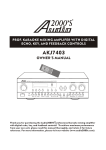
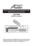
1
DOE 2.16 – Radiation Survey Instrumentation Study Guide
00ICP329 Rev. 0
Page 1 of 24
Course Title:
Module Title:
Module Number:
Radiological Control Technician
Radiation Survey Instrumentation
2.16
Objectives:
2.16.01
List the factors which affect an RCT's selection of a portable radiation survey
instrument, and identify appropriate instruments for external radiation surveys.
) 2.16.02
Identify the following features and specifications for standard radiation survey
instruments used at your facility:
a.
Detector type
b.
Instrument operating range
c.
Detector shielding
d.
Detector window
e.
Types of radiation detected/measured
f.
Operator-adjustable controls
g.
Markings for detector effective center
h.
Specific limitations/characteristics
)
2.16.03
Identify the following features and specifications for high range instruments used
at your facility:
a.
Detector type
b.
Instrument operating range
c.
Detector shielding
d.
Detector window
e.
Types of radiation detected/measured
f.
Operator-adjustable controls
g.
Markings for detector effective center
h.
Specific limitations/characteristics
)
2.16.04 Identify the following features and specifications for neutron detection and
measurement instruments used at your facility:
a.
Detector type
b.
Instrument operating range
c.
Types of radiation detected/measured
d.
Energy response
e.
Operator-adjustable controls
f.
Specific limitations/characteristics
DOE 2.16 – Radiation Survey Instrumentation Study Guide
00ICP329 Rev. 0
Page 2 of 24
References:
1.
2.
3.
4.
5.
6.
7.
8.
9.
10.
11.
12.
13.
10 CFR Part 835 Occupational Radiation Protection
DOE-STD-1098-99 U.S. Department of Energy Radiological Control Standard
"Basic Radiation Protection Technology"; Gollnick, Daniel; Pacific Radiation
Corporation, Altadena, 4th Edition, January 2000.
Knoll, Glenn F., "Radiation Detection and Measurement," 3rd Edition, John
Wiley & Sons, New York, 2000.
ANSI N323A-1997, American National Standard Radiation Protection
ANL-88-26 (1988) "Operational Health Physics Training"; Moe, Harold;
Argonne National Laboratory, Chicago.
TPR-7325 – Portable Health Physics Instrumentation Functional and Performance
Checks
Instrumentation Test and Calibration, Portable Survey Instruments.
Eberline RO-20 Ion Chamber Technical Manual
Bicron Micro Rem Survey Meter User’s Manual
AMP Operation and Maintenance Manual
Ludlum Model 14C Technical Manual; January, 2006
Form 441.70 - “Instrument Return Tag”
DOE 2.16 – Radiation Survey Instrumentation Study Guide
00ICP329 Rev. 0
Page 3 of 24
INTRODUCTION
External exposure controls used to minimize the equivalent dose to personnel are based on the
data taken with portable radiation survey instruments. An understanding of these instruments is
important to ensure the data obtained are accurate and appropriate for the source of radiation.
This lesson contains information about widely used portable radiation survey instruments.
Many factors can affect how well the measurement reflects the actual conditions, such as:
•
Selection of the appropriate instrument based on type and energy of radiation,
radiation intensity, and other factors.
•
Correct operation of the instrument based on the instrument operating
characteristics and limitations.
•
Calibration of the instrument to a known radiation field similar in type, energy
and intensity to the radiation field to be measured.
Other radiological and non-radiological factors that affect the instrument response, such as
Radio Frequency fields, radioactive gases, mixed radiation fields, humidity and temperature.
2.16.01
List the factors which affect an RCT's selection of a portable radiation
survey instrument, and identify appropriate instruments for external
radiation surveys.
Instrument Characteristics
To ensure the proper selection and operation of instruments, the instrument operator must
understand the operating characteristics and limitations of each instrument available for use.
There are general characteristics which apply to the instruments described in the following
sections.
1. Detector Type
• Ion chambers are accurate across a range of photon energies and are closest to
being tissue equivalent. A correction factor is needed when used for measuring
beta radiation.
•
Geiger-Mueller (GM) detectors
1. GM detectors operate in the pulse mode, or the mode that counts each
individual pulse. Since any ionization in a GM detector causes the same large
pulse, any radiation interaction in the detector will be counted. All the pulses
are of the same large size regardless of the energy or type of radiation;
therefore, all information on the type and energy of the radiation is lost. GM
detectors are very sensitive; however, they lack the direct correlation to
energy deposited and are not as useful as ion chamber instruments for
assessing exposure rates. GM detectors should be calibrated to the photon
energy to be measured.
DOE 2.16 – Radiation Survey Instrumentation Study Guide
00ICP329 Rev. 0
Page 4 of 24
2. Tube shaped GM detectors are designed so that the walls are close to the
detector gas, since gamma interactions in the wall are much more likely than
in the fill gas.
3. Energy compensated GM detectors – GM detectors over-respond to low
energy photons. To reduce this over-response, energy compensated GM
detectors use shielding to filter out low energy photons.
•
NaI scintillation detectors are used for measuring low intensity fields.
•
Proportional counters may be used for neutron measurement.
2. Instrument Operating Range
• The operating range of the instrument must match the intensity of the field being
surveyed. A low range instrument is needed for low intensity fields and a high
range instrument is needed for high intensity fields.
• Extendible instruments are generally appropriate for high radiation fields where
the dose to the RCT is an ALARA consideration.
3. Detector Shielding
• The mounting case surrounding the detector may shield low energy radiation from
entering the detector. This factor may be desirable to measure deep dose.
4. Detector Window
• Radiation survey instruments generally have windows that have the same density
thickness as the dead layer of human skin (7 mg/cm2). This is because if the
radiation does not penetrate this window then it does not penetrate the layer of
dead skin, and so it does not contribute to dose. In contrast, contamination
monitoring instruments have thinner windows.
5. Types of Radiation Detected/Measured
• Beta and photon (x-ray and gamma ray)
• Neutron
6. Operator Adjustable Controls
• On-off switch
• Range selector switch
• Battery check
• Ion chambers generally have a zero adjustment
7. Markings for Detector Effective Center
• The effective center of the detector, as defined in ANSI N323, is the point within
the detector that produces, for a given set of irradiation conditions, an instrument
DOE 2.16 – Radiation Survey Instrumentation Study Guide
00ICP329 Rev. 0
Page 5 of 24
response equivalent to that which would be produced if the entire detector were
located at that point. The effective center can be thought of as the point in the
detector where the measurement of the radiation intensity is taken. Portable
radiation survey instruments are calibrated in a uniform field of radiation larger
than the volume of the detector, so that the same radiation intensity is seen
throughout the detector. Therefore, the reading "taken" at the effective center
represents the rate value in all portions of the detector. If the radiation field over
the whole detector is not uniform, the exposure rate will not be uniform over the
entire detector volume. For non-uniformly irradiated detectors, the displayed
value, as "taken" at the effective center, will not reflect the actual exposure rate
value and a correction factor may be appropriate.
Factors Affecting Instrument Selection
As discussed, the selection of the proper instrument is critical to ensure the data obtained are
accurate and appropriate. The instrument is selected based on the characteristics and
specifications for that instrument as compared to the required measurements. Several factors
should be considered when selecting the instrument.
1. Type of Data Required
• Distinguish clearly between external radiation surveys and contamination
monitoring. External radiation surveys require an instrument that reads R/hr,
mR/hr, rem/hr, mrem/hr, etc., rather than counts per minute, etc.
2. Accuracy
• Ion chambers (which read current instead of counting pulses) have a flat energy
response. This means they are accurate across a wide range of photon energies.
A good choice for external beta-gamma surveys is the Eberline RO-20 or the
Bicron RSO-5E0 ion chamber.
3. Type of Radiation to be Measured
• Ion chambers are often used to measure beta and gamma radiation.
• During radiation surveys, an RCT does not measure alpha radiation since alpha
particles do not penetrate the outer layer of dead skin (7 mg/cm2,) and therefore
are considered to be an internal hazard only.
• Special detectors are used to detect and measure neutron radiation.
4. Intensity of the Radiation (dose rate)
• For high intensity radiation fields (>5 R/hr) use an extendible instrument, such as
a Teletector, to maintain dose ALARA.
• Ion chambers are usually not sensitive enough to use for low intensity fields (less
than 1 mrem/hr).
• The Bicron Micro Rem is used to measure low intensity fields (less than 1
mrem/hr).
DOE 2.16 – Radiation Survey Instrumentation Study Guide
00ICP329 Rev. 0
Page 6 of 24
5. Energy of the Radiation to be Measured
• Low energy radiation will not penetrate either the skin or the window of most
radiation survey instruments.
• GM detectors over-respond to low energy gammas.
• Neutron detectors under-respond to high energy neutrons.
6. Environmental Factors
• Ion chambers are usually vented to air, so radioactive gases or high humidity
affect the instrument response.
7. Procedures
• Facility procedures may dictate which instrument will be used in certain
circumstances.
Preoperational Check
Once the proper type of instrument has been identified, a pre-operational check is essential and
must be performed in accordance with TPR-7325, Portable Health Physics Instrumentation
Functional and Performance Checks.
1. Physical Damage
• Perform a physical inspection of the instrument by checking for obvious physical
defects or damage, especially of the probe. Replace the cable if necessary.
2. Calibration Sticker
• Verify the instrument is calibrated and has not exceeded the calibration due date.
3. Battery
• Perform a battery check to verify the battery condition is within the acceptable
range. Change the batteries if necessary.
4. Zero
• Perform a zero adjustment for ion chambers instruments.
5. Source Check
• Perform a source response check as required by TPR-7325, Portable Health
Physics Instrumentation Functional and Performance Checks.
Note: If any instrument check is found to be unsatisfactory and cannot be corrected (i.e.,
change-out of cable), the instrument must be tagged out-of-service (OOS) and a Form 441.70,
“Instrument Return Tag” prepared. The instrument is then segregated until it is returned to the
Health Physics Instrument Laboratory for repair.
DOE 2.16 – Radiation Survey Instrumentation Study Guide
00ICP329 Rev. 0
Page 7 of 24
RADIATION SURVEY INSTRUMENT FEATURES
) 2.16.02
Identify the following features and specifications for standard radiation
survey instruments used at your facility:
a.
Detector type
b.
Instrument operating range
c.
Detector shielding
d.
Detector window
e.
Types of radiation detected/measured
f.
Operator-adjustable controls
g.
Markings for detector effective center
h.
Specific limitations/characteristics
EBERLINE MODEL RO-20 ION CHAMBER
The Eberline Model RO-20 is a portable air ion chamber
instrument used to detect beta, gamma, and x-ray radiation. The
RO-20 has five linear ranges of operation to measure exposure rate
for x-ray and gamma radiation. The ion chamber is vented to
atmospheric pressure and is specifically designed to have a flat
energy response across a wide range of photon energies. The RO20 is calibrated to gamma radiation (Cs-137).
A single rotary switch turns the instrument on or off, provides
battery checks, checks the zero setting, and selects the range of
operation.
The detector wall of the RO-20 is constructed of 0.20 inch
conductive plastic approximately 640 mg/cm2. It is housed inside
a 0.063 inch wall aluminum case, providing a total detector
shielding of approximately 1000 mg/cm2 total thickness.
The beta window is constructed of two layers (one on the chamber, one on the can) of 0.001 inch
thick Mylar, providing an open window detector shielding of approximately 7 mg/cm2 total
thickness, comparable to the layer of dead skin on humans. The beta shield is on the bottom of
the case, which has a positive friction lock. It has a density thickness of approximately 1000
mg/cm2 thickness.
The five linear ranges of the RO-20 are as follows:
• 0-5 mR/hr
• 0-50 mR/hr
• 0-500 mR/hr
• 0-5 R/hr
• 0-50 R/hr
DOE 2.16 – Radiation Survey Instrumentation Study Guide
00ICP329 Rev. 0
Page 8 of 24
Response time for the RO-20 is 5 seconds from 0 to 90% of final reading and the
linearity is within + or – 5% of full scale. Display readings are independent of battery
voltage when battery check indications are in the green arc.
External controls consist of:
• Range switch including on/off, Zero, and battery check positions.
• The Zero knob is used to set meter to zero when zero position of range switch is
selected when in no significant radiation field.
• Light switch for meter light.
Internal controls consist of five calibration controls, one for each range.
The Model RO-20 uses five C cell batteries for main power (Battery 1) and ten 3-volt
lithium coin cells (30 volts) for Chamber bias (Battery 2). Only the C cell batteries
(Battery 1) are replaceable by the user. Battery life varies according to usage and battery
type.
The Model RO-20 has an operating temperature range from -40° F to 140° F. In
temperatures less than 0° F, fresh alkaline batteries should be used.
Operation of Model RO-20
Before using the instrument, the RCT should:
• Check Battery 1 and Battery 2. The meter should indicate in the green Battery
Check arc. Do not leave the switch in the Battery 2 position for any extended
period of time, as this will drain the special lithium coin cell batteries.
• Turn function switch to the Zero position and zero the meter on the low range
(0-5 mR/hr). This setting should be checked and readjusted as necessary during
use. You can zero the meter while in a radiation field to compensate for
background levels by merely selecting the Zero position. Zero does not need to
be reset when switching to higher ranges.
• Set function switch to desired range of operation. The position selected is the full
scale reading for that range.
When measuring beta, low energy gamma, or low energy x-ray emissions, open the
sliding β shield on the bottom of the case and face the bottom of the instrument toward
the radiation source. To open or close the shield, depress the friction release button on
the left side of the case and manually move the slide, or let it fall due to gravity. When
the shield is open, make sure to protect the thin face of the Mylar window against
puncture damage.
When switching from the R/hr ranges to the mR/hr ranges, transient electronic noise may
cause a temporary deflection of the meter. This can be minimized by first selecting the
500 mR/hr setting, letting the needle settle, and then switching to the lower ranges.
The effective center of the ion chamber is marked by dimples at the front and
sides of the instrument.
DOE 2.16 – Radiation Survey Instrumentation Study Guide
00ICP329 Rev. 0
Page 9 of 24
BICRON RSO-50E ION CHAMBER
The Bicron RSO-50E instruments are portable air-vented ion
chamber instruments used to detect and measure gamma, x-ray
and beta radiation. The Bicron RSO series of instruments are
very similar in design and construction to the Eberline RO-2
series of instruments.
Detector Type
• Ionization Chamber
⋅
A phenolic, or plastic, cylinder of 3 in.
diameter and 12.7 in3 (208 cm3) volume
with one end open but covered by a Mylar
window.
⋅
Fill gas: air (vented to atmosphere through
a silica gel desiccant pack).
Instrument Operating Range
The five linear ranges of the RSO-50E are as follows:
•
•
•
•
•
0-5 mR/hr
0-50 mR/hr
0-500 mR/hr
0-5 R/hr
0-50 R/hr
Detector Shielding
The active volume of the detector is shielded from the side by the detector wall and the
instrument case and from the bottom by the movable beta shield and two layers of
window. The detector wall is 200 mg/cm2 and the 0.13 cm thick aluminum case is about
345 mg/cm.
Detector Window
• Closed window- 1000 mg/cm2sliding beta shield.
• Open window - 7 mg/cm2 Mylar.
Types of Radiation Detected/Measured
The Bicron RSO series of instruments are designed to measure gamma, X-ray and beta
radiation but will detect (not measure) fast neutron radiation. The instruments will read
approximately 10%, in mR/hr, of the true neutron field, in mrem/hr. Like the Eberline
RO-20, the Bicron RSO series instruments will not respond to alpha radiation because the
alpha particles are shielded before they reach the detector.
Energy Response
The RSO-50E measures photon radiation within +20% for photon energies from 12 keV
to 7 MeV (beta shield open). The minimum energy increases to 25 keV if the shield is
DOE 2.16 – Radiation Survey Instrumentation Study Guide
00ICP329 Rev. 0
Page 10 of 24
closed, and to about 40 keV through the side of the instrument. The RSO-50E measures
beta radiation >70 keV.
Operator-Adjustable Controls
RSO-50E range switch with OFF, ZERO, and BATT positions.
• Switch ranges labeled as 5, 50 and 500 mR/hr and 5 and 50 R/hr.
• ZERO position works in conjunction with ZERO knob to electronically zero the
meter.
• BAT position checks the two batteries used to power the instrument circuitry and
detector bias.
•
OFF position turns the instrument off.
Markings for Detector Effective Center
The effective center markings are the stamped circles with a plus sign in the circle and
are located on the sides and front of the instrument case. If the radiation field over the
whole detector is not uniform (such as from surface contamination, radiation streaming,
or from a small point source) the displayed value may need to be corrected.
Specific Limitations/Characteristics
The response time is approximately 5 sec from 0-90% of the final reading.
Correction factors may be needed when the radiation field is not uniform over the entire
detector. High humidity or moisture can cause leakage currents in the detector and cause
erratic meter readings. The detector is vented through a desiccant, or drying medium,
contained in a plastic box. The desiccant can become saturated and will need
replacement if the crystals start to turn clear or pink.
Like the Eberline RO-20, the detector is vented to atmosphere; therefore, any change in
atmospheric density changes the air density in the detector.
•
An increase in temperature will lower the air density in the detector and cause a
lower response.
•
An increase in atmospheric pressure will cause an increase in air density in the
detector and cause a higher response.
•
Tables are provided in the technical manuals for correcting the instrument
response due to changes in pressure or temperature.
•
A change in response of about 10% will occur if the instrument was calibrated at
room temperature and used in an environment that is different by about 50°F.
•
Normal atmospheric pressure variations are small enough to be ignored.
Because the detector is vented to atmosphere, radioactive gases can enter the detector and
cause a reading.
DOE 2.16 – Radiation Survey Instrumentation Study Guide
00ICP329 Rev. 0
Page 11 of 24
Bicron Micro Rem Survey Meter
The Bicron Micro Rem Survey Meter reads absorbed
dose rate directly so no conversion from mR/h is
required.
The tissue-equivalent scintillator used in the Micro
Rem gives it a nearly flat, rem energy response. This
rem response is based on the equivalent dose index for
1 cm (0.39") depth.
This instrument gives tissue-equivalent photon
response for X-ray and gamma radiation from
environmental levels of 0 to 20 µrem/h full scale up to
normal survey levels of 200 mrem/h full scale.
Range – Five linear ranges:
• x0.1 range from 0 to 20 μrem/h
• x1 range from 0 to 200 μrem/h
• x10 range from 0 to 2,000 μrem/h
• x100 range from 0 to 20,000 μrem/h
• x1000 range from 0 to 200,000 μrem/h
The Bicron Micro Rem survey meter detects gamma and x-ray from 40 keV to 1.3 MeV
using an internally mounted tissue-equivalent organic scintillation detector. A lowenergy option is included on some instruments used at ICP which allows detection to as
low as 17 keV. The instruments with the low-energy option can be readily identified by
the presence of a visible circular window on the front of the case.
The instrument has an eight-position rotary switch used for turning the meter on/off,
performing battery check, checking high voltage and selecting proper scale (x1000, x100,
x10, x1, and x0.1). It may or may not have the extended probe on the front. The Bicron
Micro Rem meter needs no warm up time.
Some models have a built-in speaker (with panel-mounted switch labeled off, pulse, and
alarm) to provide an audible click whose rate is proportional to the dose rate on the x0.1,
x1, and x10 ranges. In addition, a full scale alarm sounds when the meter reading is
greater than full scale on any dose rate range. A panel-mounted momentary pushbutton
switch resets the meter to zero.
Operation of Bicron Micro Rem Meter
• Turn instrument on to “bat” position; meter should display a reading with the “bat
ok” check. If it doesn’t, replace the batteries.
DOE 2.16 – Radiation Survey Instrumentation Study Guide
00ICP329 Rev. 0
•
•
Page 12 of 24
Check High Voltage by turning control knob to “HV” position. The meter should
read within the “HV ok” check band. If it falls outside the band, the meter is in
need of service.
Turn control knob to desired range. The meter reading is the total tissueequivalent exposure rate for all the energies the internal probe is capable of
detecting, in μrem/h. Make sure you multiply the meter reading by the control
switch multiplier. On some models, you can quickly reset the meter to zero by
pressing the reset pushbutton switch.
Ludlum Model 14C Survey Meter with Model 44-6 Sidewall G-M Detector
The Ludlum Model 14C with sidewall G-M detector is used for measuring beta-gamma
emissions. Since this instrument does not read absorbed dose directly, it should not be used for
determining dose rates. The Ludlum Model 14C is typically used in facilities with the potential
for a criticality event for measuring field intensities and activation levels.
Detector Type
Halogen quenched G-M tube. It is not energy
compensated; therefore it will over-respond to
low energy photons.
Instrument Operating Range
The instrument provides an overall range of 0
– 2000 mR/hr
•
•
•
•
•
x0.1 range from 0 to 0.2 mR/h
x1 range from 0 to 2 mR/h
x10 range from 0 to 20 mR/h
x100 range from 0 to 200 mR/h
x1000 range from 0 to 2,000 mR/h
Detector Shielding
1000 mg/cm² polished stainless steel housing with a rotary beta shield
Detector Window
30 mg/cm² stainless steel wall
Beta Cut Off: Approximately 200 keV (window open)
Types of Radiation Detected/Measured
Beta and gamma
Operator-Adjustable Controls
The range multiplier selector switch is a six position switch marked OFF, X1000, X100,
X10, X1, X0.1. Moving the range selector switch to one of the range multiplier positions
provides the operator with an overall range of 0-2000 mR/hr.
DOE 2.16 – Radiation Survey Instrumentation Study Guide
00ICP329 Rev. 0
Page 13 of 24
Audio ON-OFF toggle switch: in the ON position, the switch energizes the speaker,
located on the left side of the instrument. The frequency of the clicks is relative to the
rate of the incoming pulses. The higher the rate, the higher the audio frequency.
Fast-Slow toggle switch: selecting the fast, "F", position of the toggle switch provides
90% of final meter reading in four seconds. In slow, "S", position, 90% of final meter
reading takes 22 seconds. Set on "F" for fast response and large meter deviation. "S"
position should be used for slow response and damped meter deviation. The fast
response setting should be used when performing an initial survey or when trying to
locate sources of radiation. Switch to slow response when more accurate measurements
are needed.
RES button: when depressed, provides a rapid means to drive the meter to zero.
BAT check: when depressed, provides a visual means of checking the battery charge
status.
Specific Limitations/Characteristics
Operates on two standard D cell batteries.
Uses an internal GM detector on the X1000 range.
) 2.16.03
Identify the following features and specifications for high range instruments
used at your facility:
a.
Detector type
b.
Instrument operating range
c.
Detector shielding
d.
Detector window
e.
Types of radiation detected/measured
f.
Operator-adjustable controls
g.
Markings for detector effective center
h.
Specific limitations/characteristics
W.B. JOHNSON EXTENDER MODEL 2000W
The W. B. Johnson Model 2000W is an
extendable, telescoping-rod survey meter
used for the measurement of photon
exposure rates with a window for detection
of beta radiation.
Detector Type
The W. B. Johnson Extender Model 2000W
uses two energy compensated GM detectors
(a low range and a high range) that are
DOE 2.16 – Radiation Survey Instrumentation Study Guide
00ICP329 Rev. 0
Page 14 of 24
located at the end of a telescoping probe. Both detectors are sealed GM tubes with
halogen-quenched argon fill gas contained in an energy compensating case. The detectors
are centered in the probe housing so that equal readings may be obtained in any direction.
Inside the telescoping probe, cabling provides high voltage to the detectors and carries
the signal back to the electronics.
Instrument Operating Range
Turning the selector switch clockwise steps through the battery check function, and the
desired range can be selected:
•
•
•
•
•
•
•
0–1000 R/hr
0–100 R/hr
0–10 R/hr
0–1000 mR/hr
0-100 mR/hr
0-10 mR/hr
0-1 mR/hr
(High Range Detector)
(High Range Detector)
(High Range Detector)
(Low Range Detector)
(Low Range Detector)
(Low Range Detector)
(Low Range Detector)
Detector Shielding
The detectors are shielded by the probe housing and a removable plastic beta cap on the
end of the low range detector.
Detector Window
Remove the plastic beta end cap to survey for beta radiation. This will expose the thin
Mylar® window at the end of the probe. Be careful not to unscrew the Mylar® beta
window.
Types of Radiation Detected/Measured
The W. B. Johnson Extender Model 2000W will measure gamma radiation on both low
and high ranges and can detect (but not measure) beta radiation when using the low range
detector with the beta end cap removed. It is important to note that beta response for this
instrument is not accurate and should be used for detection purposes only. Also, if the
low range detector is used without the beta end cap installed (often missing in the field),
the instrument will not provide an accurate gamma measurement in a beta/gamma field.
Operator-Adjustable Controls
The Extender has a built-in speaker and light. By using the front panel switch, the light
and sound functions of the Extender are activated with all combinations.
The selector switch operates in both directions to step through the battery check and the
desired range.
DOE 2.16 – Radiation Survey Instrumentation Study Guide
00ICP329 Rev. 0
Page 15 of 24
Markings for Detector Effective Center
The location of the low range detector is marked by the white line circling the probe near
its end. The location of the high range detector is marked by the yellow line circling the
probe further in from the end. The low range detector is the larger of the two detectors.
Specific Limitations/Characteristics
Do not twist the telescopic extension. It will damage the internal cabling. Operate the
extension only by hand.
The low range detector has a 4 second response time. The high range detector has a 1.5
second response time.
EBERLINE RO-7
The RO-7 series instrument provides remote
monitoring in high range beta and gamma radiation fields. The RO-7 consists of a basic
autoranging digital readout instrument, three interchangeable detectors, and various
interconnecting devices. The detectors may be interconnected to the instrument by flexible
cables of different lengths, by rigid extensions of different lengths or by use of an underwater
housing.
Detector Types
All three detectors are air-vented ion chambers contained in a plastic-lined (phenolic) aluminum
housing. The detector fill gas is air. The detector housing also contains other electronics, such
as an operational amplifier and detector identification circuitry.
DOE 2.16 – Radiation Survey Instrumentation Study Guide
00ICP329 Rev. 0
Page 16 of 24
The three available detectors are as follows:
• The RO-7-LD is a low-range, gamma-only detector.
• The RO-7-BM is a mid-range, beta/gamma detector, with beta window.
• The RO-7-BH is a high-range, beta/gamma detector, with beta window.
Each detector is labeled at the connector end of the detector.
• NOTE: Two small screws on the label are marked ZERO and CAL. These
should only be adjusted at calibration and must not be adjusted by the
operator.
Instrument Operating Ranges
The operating range of the instrument is dependent on the detector that is connected to
the instrument.
• The range of the RO-7-LD detector is 0-2 R/hr.
• The range of the RO-7-BM detector is 0-200 R/hr.
• The range of the RO-7-BH detector is 0-20 kR/hr (20,000 R/hr).
Detector Shielding
All three detectors have a phenolic liner and aluminum housing.
Detector Window
The RO-7-BM and RO-7-BH detectors each have a 7 mg/cm2 Mylar window. The Lucite
cap for the beta window is 100 mg/cm2.
Types of Radiation Detected/Measured
As previously mentioned, the RO-7-LD detector measures only gamma and X-ray
radiation. Both beta and alpha radiation are shielded by the detector housing. The
neutron radiation response is insignificant due to the small size of the detector. The
actual detectors in the RO-7-BM and RO-7-BH detector assemblies are identical. Both
detect and measure gamma, X-ray and beta radiation.
Alpha response is eliminated by the 7 mg/cm2 window (same density thickness as the
outer layer of skin). Neutron radiation response is even smaller than the RO-7-LD due to
the smaller detector volume.
Energy Response
The RO-7-LD responds to photon radiation between 50 keV and 1.3 MeV (+20%). The
RO-7-BM and RO-7-BH detectors respond to photon radiation differently depending on
orientation and whether the Lucite cover is in place.
• Lucite cover off - 10 keV to 1.3 MeV (+20%).
• Lucite over on - 25 keV to 1.3 MeV (+20%).
• Shield on, from the side - 50 keV to 1.3 MeV (+20%).
• The beta response for the RO-7-BM and RO-7-BH detectors is for beta
energies >70 keV.
DOE 2.16 – Radiation Survey Instrumentation Study Guide
00ICP329 Rev. 0
Page 17 of 24
Operator-Adjustable Controls
The ON/OFF switch is the only range control because the instrument identifies the
detector model and adjusts the readout accordingly. A low battery condition is indicated
by a "colon" under the battery mark on the meter. The ZERO knob will zero the LCD
readout. A meter face light is turned on/off by the small switch in front of the pistol grip.
Detector Effective Center
No markings are provided for the detector effective center.
Specific Limitations/Characteristics
The response time of the basic instrument is 2.5 seconds to 90% of the final reading. The
correction factor for the true beta measurement is 1.5 as recommended by the
manufacturer.
Interconnecting devices from the detector to the instrument that are available from the
manufacturer are the:
• 15 ft flexible cable
• 60 ft flexible cable
• 2 ft rigid extension
• 5 ft rigid extension
• Stainless-steel underwater housing with 60 ft of cable.
Calibration is associated with the probe; therefore the probes are interchangeable with
any instrument.
MGP Area Monitor Probe (AMP 50, 100)
AMP 50
AMP 100
General Description
The Area Monitor Probe (AMP), an energy compensated GM-tube based rate meter, is
designed for measurements of dose rates from gamma radiation.
An automatic self-diagnostic procedure continuously checks both meter and detector and
reports any case of detector failure. The meter also alarms if the reading exceeds the
DOE 2.16 – Radiation Survey Instrumentation Study Guide
00ICP329 Rev. 0
Page 18 of 24
threshold value, or if the probe is in a field higher than the measuring range, or if the
battery potential drops below an acceptable value. The threshold can be selected from a
list of 11 preset values. When the meter is turned off, the last parameters (threshold value,
calibration factor, dose status, communication mode, communication baud rate) are
retained in memory and will be recalled the next time the instrument is turned on.
The AMP may be used in one of four ways:
•
•
•
•
By locally reading the digital display via the hand held meter display.
By connecting the meter to a PC.
By connecting the meter to a DDC-16/AM-16 Area Monitor (wired).
By connecting the meter to an external WRM transmitter (wireless).
The AMP system contains four components: the meter, the cable, the probe head, and the
communication interface. Connection between the meter and the detector is accomplished
by way of a four-wire shielded cable of up to 100 meters (330 feet) in length. An optional
WRM transmitter may be connected via a standard four-wire telephone cable. Two types
of meter-to-PC cables are available. It is important to note that the components of the
AMP system are calibrated as a matched set, and therefore cannot be swapped between
different instruments.
The AMP’s connections and probe head feature watertight sealing to allow for use in
underwater applications.
Applications
• Real time monitor applications include any area with radiation levels from 0.001
mR/h up to 15,000 R/h. For example, the probe head may be placed directly onto
a filter housing or against a resin tank for the purpose of providing survey data or
resin transfer results.
• Replacement of “difficult to calibrate” underwater instruments.
• Provides a rugged detector for environments where the use of an electronic
dosimeter is undesirable.
• Provides real-time, remote monitoring in geometries developed for extendible
“pole” rate meters.
• Local readout of hand-held meter allows its use as a portable survey instrument.
Specifications
Display is an LCD readout showing:
• Four digits for accurate and easy readout
• Detector failure
• Low battery
• Overflow
• Threshold
Audio is internally mounted element used for alarm and “chirp” functions.
DOE 2.16 – Radiation Survey Instrumentation Study Guide
00ICP329 Rev. 0
Page 19 of 24
Measuring Units: AMP 50 measures in mR/h while the AMP 100 measures in units of
R/h.
Measuring Range:
• AMP 50 measures from 0.05mR/h to 4000 mR/h
• AMP 100 measures from 0.005 R/h to 1000 R/h
Display Range:
• AMP 50 displays from 0.001 mR/h to 4000 mR/h
• AMP 100 displays from 0.001 R/h to 1000 R/h
Controls:
• ON/OFF push-button
• RESET push-button
• Speaker push-button
Power Source:
The AMP uses one 9-volt battery or an external 9 volt power supply.
• 50 hours minimum continuous operation using an alkaline battery (speaker off)
• Automatic battery check under full load
Detector:
Energy compensated GM tube detectors.
Accuracy:
+ or – 10% of reading with the measuring range.
Energy Range:
70 keV to 2.0 MeV.
Alarms
There are four alarms associated with the AMP:
• Detector Alarm – If the detector is defective or disconnected, the ERR. LCD will
blink on the display and an interrupted audible alarm will be activated. To mute
the alarm, press the “SPEAKER” push-button. If the detector is defective the
alarm will be activated as follows:
•
o AMP 50 – after 2 minutes
o AMP 100 – after 15 minutes
Battery Alarm – If battery voltage decreases below 6.2 Volts, the bAt, LCDs blink
on the display and an interrupted audible alarm is activated. To display the
measured readings and mute the audible alarm, press the SPEAKER push-button.
After the SPEAKER push-button is pressed, the bAt. LCDs will reappear every 5
DOE 2.16 – Radiation Survey Instrumentation Study Guide
00ICP329 Rev. 0
Page 20 of 24
minutes for 2 seconds, and every 30 minutes accompanied by an audible beep to
remind users of low battery condition.
•
Overflow Alarm – If the displayed count rate is higher than the meter’s measuring
range, the OFLO LCDs will blink on the display and an interrupted audible alarm
is activated. To mute the audible alarm, press the SPEAKER push-button.
•
Threshold Alarm – If the reading exceeds threshold value, the ALr. LCDs and the
reading are displayed alternately, accompanied by an audible beep. Pressing the
SPEAKER button mutes the alarm, but the ALr. LCDs and the reading are
continuing to be displayed alternately, until the reading decreases to 75% of the
threshold value. If the reading exceeds threshold value and then quickly decreases
to below 75% of threshold value, the ALr. LCDs and the beep are automatically
cancelled, even though the SPEAKER push-button has not been pressed.
General Functions
Reading reset: To reset the reading press the “RESET” push-button. The reset function
provides a rapid means of discharging the display reading and enables accurate
measurement of low-level count rate.
For operating “RESET” perform a short press (less than 2 seconds) on “RESET/MODE”
push-button.
Audible Alarm: In the case of threshold alarm or instrument failure, the audible alarm is
activated, to mute the audible alarm, press the “SPEAKER” push-button.
For operating “MODE” perform a long press (more than 3 seconds) on “RESET/MODE”
push-button.
Operation of the AMP
Press ON/OFF push-button.
•
A short self-test procedure indicated by displaying all the segments on the
display, and emitting a beep for a short period is carried out. After the test, the
meter is ready for use.
The meter utilizes an auto-ranging display:
DOE 2.16 – Radiation Survey Instrumentation Study Guide
00ICP329 Rev. 0
Page 21 of 24
AMP-50 (mR/h)
AMP-100 (R/h)
0.001 – 0.999
0.001 – 9.999
1.00 – 9.99
10.00 – 99.99
10.0 – 99.9
100.0 – 999.9
100 – 999
1000 – 3999
When the meter is turned on the following parameters are displayed:
1. EPROM version:
2. Unit ID#:
3. Dose status:
4. Communication mode:
5. Meter baud rate:
)
EPR. Æ 020- Æ -305 (020305)
Id. Æ 123- Æ -756 (123756)
d-0 (without dose function)
d-1 (with dose function)
tri or Au: 04 or Au: 10 Au: 30 Au: 60
300, 4800, 9600
2.16.04 Identify the following features and specifications for neutron detection and
measurement instruments used at your facility:
a.
Detector type
b.
Instrument operating range
c.
Types of radiation detected/measured
d.
Energy response
e.
Operator-adjustable controls
f.
Specific limitations/characteristics
NRD 9" Neutron Ball with BF3 Tube
The NRD 9-inch diameter neutron ball with BF3 tube is a
portable instrument for the detection and measurement of the
dose rate from neutron radiation. Although the neutron ball may
be used with a variety of meters, at the ICP it is normally
attached to the E-600.
Detector Type
The detector is a proportional counter consisting of a BF3 tube in
a 9 inch, cadmium loaded polyethylene sphere.
The NRD 9" neutron ball is a 9 inch diameter, cadmium loaded,
polyethylene sphere with a BF3 proportional tube in the center of
DOE 2.16 – Radiation Survey Instrumentation Study Guide
00ICP329 Rev. 0
Page 22 of 24
the sphere. The BF3 (boron trifluoride) detector design allows the detection of neutrons
only, and the rejection of other radiation. The thermal neutron capture reaction with the
10
B results in gas ionization pulses caused by the alpha particle from the reaction:
1
0
n +105B→37Li + 24He
The 9 inch diameter polyethylene sphere is used to moderate the neutrons. The
polyethylene has a high percentage of hydrogen which thermalizes the fast and
intermediate energy neutrons. Those neutrons that are thermalized in the sphere can be
detected in the BF3 tube. The cadmium loading is a thin sheet of cadmium placed at a
radius of about 7 cm inside the polyethylene sphere to help reduce the over response to
lower energy neutrons.
Instrument Operating Range
The E-600 will readout in multiples of rem/h. Pressing the up and down range selector
arrows will increase or decrease it one decade. The lowest available range is 0-1 mrem/h.
The highest available range is 0-1000 krem/h. However, with the NRD ball attached the
E-600 is calibrated for an operating range of 1–10,000 mrem/hr.
Types of Radiation Detected/Measured
Neutron radiation is measured. Alpha and beta radiation are not detected because they do
not penetrate the detector shielding. Gamma radiation passes through the detector
shielding but is rejected by the BF3 proportional chamber.
Since the BF3 detector is operated in the proportional region, the pulses from the alpha
particles are larger than pulses from other interactions and trigger a pulse height
discriminator in the instrument circuitry.
Energy Response
Neutron energy range: Thermal to 10 MeV
Neutron energy response: Over-responds to intermediate energy neutrons
Operator-Adjustable Controls
The E-600 has numerous operator adjustable controls. For neutron surveys, the operating
mode selector switch should be placed in the ratemeter position.
Specific Characteristics/Limitations
The detector is a sealed pressurized cylinder and is not affected by changes in humidity,
radioactive gases or changes in atmospheric density.
DOE 2.16 – Radiation Survey Instrumentation Study Guide
00ICP329 Rev. 0
Page 23 of 24
Neutron Survey Meter, Model REM 500
The HPI model REM 500 is a small lightweight neutron survey meter. It
eliminates the need for a large heavy moderator by measuring the
neutrons with a tissue equivalent proportional counter combined with a
256 channel multichannel analyzer. The instrument applies the
appropriate quality factors to each neutron event which results in a true
equivalent dose response.
Detector Type
• Sealed Spherical Tissue Equivalent Proportional
Counter.
• Wall Material: Tissue equivalent plastic.
• Fill Gas: Propane gas.
Instrument Operating Range
Rate Range: Autoranging from .001 mrem/h (useful from
1 mrem/hr) to 100 rem/h.
Integrate Range: Autoranging from .001 mrem to 999 mrem. Integrate range is
operational when displaying rate range.
Types of Radiation Detected/Measured
Neutron
Energy Response
• Neutron Energy Response: 70 KeV to 20 MeV
• Gamma Response: Less than 1% at 1 rad/h
Operator-Adjustable Controls
There are five buttons on the front of the instrument:
•
•
•
•
•
ON/OFF: Turns the instrument on and off.
MODE: Selects the various modes and displays. Pushing it twice will switch
between rate and integrate.
ALT: Alternate, which selects between REM and RAD. Pushing this button
will switch back and forth between RAD and REM. When in the RATE
mode, switching between REM and RAD will reset the data even if on hold.
This is not true for the INTEGRATE mode.
RESET: Puts instrument either in a hold mode or resets it.
LIGHT: Turns light on for 16 seconds.
Specific Characteristics/Limitations
• Warm Up Time: 15 seconds.
• Battery Life: 100 hours; 6 alkaline C cells. Low battery indicator in display.
• Shock: Banging on the instrument will make it respond.
DOE 2.16 – Radiation Survey Instrumentation Study Guide
00ICP329 Rev. 0
Page 24 of 24
OPERATION
Rate Mode: When first turned on, the instrument is in this mode. The integrate mode
can be obtained by pushing MODE twice from the rate mode.
The radiation level, autoranging from .001 mrem/h to 999 rem/h, is shown on the upper
left. It indicates over range by showing >1K REM/h in the display. The lower left of the
display shows the current time constant. The instrument gathers data for the time constant
period then displays it. The upper right hand corner of the display shows the remaining
time in this period. There are three Time Constant settings: 10, 30, or 60 seconds. The
number in the upper right hand corner of the display shows the time remaining in this
time constant period. Each reading is completely separate from any other reading.
The lower right hand corner shows the number of events that have been counted during
this period. When the HOLD button is pushed the word HOLD will appear in the upper
right hand corner of the display. If the battery is weak, the word LBAT will flash in the
same place.
Integrate Mode: The integrate display can be reached by pushing MODE twice from
the RATE display. The display is updated every 10 seconds.
The radiation level, autoranging from .001 mrem to 999 rem is shown on the upper left. It
indicates over range by showing 1K REM in the display. The lower left shows the time
of integration. It displays the time in HRS:MIN:SEC and will go as high as 18 hrs:12
min:15 sec before it resets to zero. It updates every second. The lower right hand corner
shows the number of events that have been counted. When the HOLD button is pushed,
the instrument recalculates the level for that second and then updates the display and
shows HOLD in the upper right hand corner of the display. If the battery is weak, the
word LBAT will flash in the upper right hand corner. The instrument will continue to
gather data until it is reset.
Change Mode: The change mode will allow adjustment of the display contrast and time
constant. It also is a way into the Check mode.
SUMMARY
This lesson has covered the specifications, features and limitations for the portable radiation
survey instruments that may frequently be used by the RCT. This knowledge should be used to
properly select and operate the instruments to ensure that the data obtained is accurate and
appropriate. The appropriate, accurate data is then used to properly assign external exposure
controls.