1
The Stick Locator Series
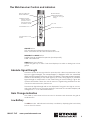
Transmitter Controls and Indicators
Load Rate
Indicators
8869
DFF
F.1
F.2
kHz
Tx Output
Jack
mA
v
kM
Battery Condition
Indicator
Frequency
Selector
Power On & Off
Relative Resistance,
Voltage, Current
Output Signal
Level Control
TX OUTPUT JACK
The Red/Black Cord, Coupler and Flexicoupler connects here to create a circuit on the
buried utility.
FREQUENCY SELECTOR
Pressing the frequency button will toggle through the available frequencies. This
model operates at 82 kHz and 8kHz.
The 82 kHz frequency is a high frequency and can be applied by direct connection,
coupler induction and transmitter induction. High frequencies are capable of jumping
disconnected shield bonds, faults, insulated couplings and other interruptions of the
conductor. The 82 kHz may induce or couple (bleed off) onto non-target conductors
within close proximity.
The 8 kHz is mid-range frequency that can be applied via direct connection. The 8kHz
is less likely to couple to adjacent conductors.
LOAD INDICATOR
The Load Rate Indicator symbol flashes to indicate signal transmission and the output
circuit impedance. When the indicator blinks 4 times per second, it is indicating a
nearly short circuit. When the indicator blinks 1 time every 3 seconds, it is indicating a
nearly open circuit.
OUTPUT SIGNAL LEVEL CONTROL
The OUTPUT SIGNAL LEVEL CONTROL adjusts the power output from the Transmitter. The
three selections include: LOW, MEDIUM, HIGH.
REALATIVE RELATIVE RESISTANCE, VOLTAGE, CURRENT
The transmitter measures both the output of the frequency and the feed back from
the transmitted frequency. Pressing the "i" button will toggle through the voltage,
current and relative resistance dispayed at the bottom of the LCD.
800.851.7347
www.rycominstruments.com
3