1
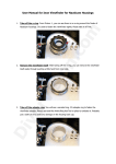
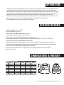
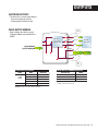
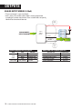
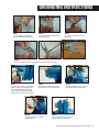
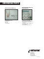
FLOW METERS OCTAVE® ULTRASONIC FLOW METER INSTALLATION & USER GUIDE 2 • OCTAVE ULTRASONIC FLOW METER INSTALLATION & USER GUIDE TABLE OF CONTENTS General Information..............................................................................................................4 Warranty.................................................................................................................................4 Included Items.......................................................................................................................4 Operation................................................................................................................................5 Specifications........................................................................................................................5 Dimensions & Weight .........................................................................................................5 Installation Handling the Flow Meter....................................................................................6 Installation Position & Location........................................................................6 Installation Examples..........................................................................................7 Installation Notes.................................................................................................8 Pipe Flanges..........................................................................................................8 Start-Up . ...............................................................................................................8 Display ....................................................................................................................................8 Outputs Electrical Outputs.................................................................................................9 Pulse Output Module . ........................................................................................9 Analog Output Module .....................................................................................10 Grounding Instructions......................................................................................................11 Grounding Parts .................................................................................................................12 OCTAVE ULTRASONIC FLOW METER INSTALLATION & USER GUIDE • 3 GENERAL INFORMATION • Do not install, operate or maintain this flow meter without reading, understanding and following the factory-supplied instructions. Otherwise, injury or damage may result. • Read these instructions carefully before beginning installation and save them for future reference. • Observe all warnings and instructions marked on the product and in this guide. • Consider handling and lifting instructions to avoid damage. • If the product does not operate normally, refer to the service instructions or call your Netafim Representative. • There are no operator-serviceable parts inside this product. WARRANTY Octave flow meters are warranted to be free from original defects in materials and workmanship for a period up to five (5) years. If the meter encounters a problem, Netafim USA will choose to cover the cost of repair or replacement based on a five (5) year pro-rated schedule as follows: Year 0 through Year 2: 100% Year 2 through Year 3: 75% Year 3 through Year 4: 50% Year 4 through Year 5: 25% All Octave flow meters must be installed with a Netafim branded Combination Air/Vacuum or Continuous Acting Air Vents to qualify for the five (5) year pro-rated product warranty. INCLUDED ITEMS • One Octave Ultrasonic Flow Meter, size as indicated on the packaging box, pieced together into a complete compact system (flow tube plus electronics). • One pre-installed Output Module, either Digital or Analog (if ordered). • Documentation includes: Installation and User Manual, Report of Factory Meter Settings and Certificate of Calibration Data. • This product has been thoroughly inspected, tested and calibrated before shipment and is ready for operation. • After carefully unpacking the meter, inspect for shipping damage before attempting to install. If any indication of damage is found, immediately contact the responsible transportation company and Netafim USA. 4 • OCTAVE ULTRASONIC FLOW METER INSTALLATION & USER GUIDE OPERATION • The Octave's measurement method is based on an ultrasonic, transit-time, dual-beam sensors that determines the length of time it takes an ultrasonic wave to travel the distance between the two sensors located in the meter's body. The sensors function as both sender and receiver, each one alternating these functions so that the ultrasonic wave travels both with and against the direction of the flow. Because the ultrasonic wave travels slower against the flow than with the flow, the time difference of the two waves allows the meter to determine the flow rate. • The Octave is a battery-powered precision flow meter designed for linear, bidirectional flow measurement of water. • Flow measurement values can be transferred through the standard digital or analog output. • The Octave display can be set up for a wide range of outputs. SPECIFICATIONS • Maximum Working Pressure: 175 psi • Liquid Temperature: 32° to 122° F • Precision Class: ISO 4064 rev.2005, Accuracy Class 2 • Configuration: Compact - display is built into the unit • Power Source: 2 ‘D’ size Lithium Batteries (not serviceable by user) • Environmental Protection: IP-68, Ambient operation temperature for display: -13° to 131° F (-25° to 55° C) • Display Units: Multi-line, programmable 9 digit LCD display • Volume Display Options: 1. Net (Forward less Reverse), 2. Forward Only, 3. Forward and Reverse Alternating • Outputs (optional): Programmable single/dual open collector pulse output our externally powered 4-20 mA loop • Connections: Flanges ANSI ISO for AWWA connection standard • Severity Levels: Environmental class C, mechanical class M1, Electromagnetic environment class E1 • Pressure Loss: ∆P 16 DIMENSIONS & WEIGHT DIMENSIONS & WEIGHT LENGTH (L) 7.9” WIDTH (B) 6.5” HEIGHT (H) 7.5” HEIGHT (h) 1.6” WEIGHT 19.8 LBS. 3” 8.9” 7.9“ 8.3“ 3.5“ 28.7 LBS. 4” 9.8” 8.7” 8.8” 4.1” 33.1 LBS. 6” 11.8” 11.2“ 11.1“ 5.5“ 70.5 LBS. H 13.4” 13.1” 6.5” 99 LBS. h 17.7” 15.9” 15.9” 8.0” 150 LBS. 12” 19.7” 19.2” 19.3” 9.6” 216 LBS. L B OCTAVE ULTRASONIC FLOW METER INSTALLATION & USER GUIDE • 13.8” 8” 10” SIZE 2” 5 INSTALLATION HANDLING THE FLOW METER Important handling Information: • Do not lift the Octave by the electronic housing. • Do not carry the Octave by the lid. • Do not place the Octave on the electronic housing. • When handling the Octave, avoid hard blows, jolts or impacts. INSTALLATION POSITION & LOCATION Installation requirements for position and location are illustrated below. PROPER INSTALLATION EXAMPLES FL OW DIR EC TIO N N CTIO IRE WD FLO N CTIO IRE WD FLO 6 • OCTAVE ULTRASONIC FLOW METER INSTALLATION & USER GUIDE N CTIO IRE WD FLO FLOW DIRECTION WRONG INSTALLATION EXAMPLES INSTALLATION INSTALLATION EXAMPLES FOR ACHIEVING TOP PERFORMANCE • Two (2) diameters of straight pipe are required when installing a 90° elbow before or after the meter. (See Figure 1) • Two (2) diameters of straight pipe are required when installing the meter upstream or downstream of a valve, tee connection or other source of significant turbulence. (See Figures 2 and 3) NOTE: The installation of the meter upstream of a pump or large valve is not recommended due to potential cavitation issues. • Five (5) diameters of straight pipe downstream of a pump (before the meter) and Two (2) diameters of straight pipe downstream of the meter are required. (See Figure 4) • Meter can be installed horizontally or vertically with the water flowing up. It is not recommended for installation where the direction of flow is below the horizontal plane. (See Figure 5) • Install a pressure breaker after the meter - pipe length should be at least Two (2) diameters and the longer the better. • To eliminate air in the pipeline and maintain accuracy, install Netafim branded Combination Air/Vacuum or Continuous Acting Air Vents right before the Octave flow meter. FIGURE 2 FIGURE 1 (2) PIPE DIAMETERS BEFORE & AFTER METER (2) PIPE DIAMETERS BEFORE & AFTER 90° ELBOWS N CTIO IRE WD FLO 2 FIGURE 3 (2) PIPE DIAMETERS BEFORE TEE CONNECTION 2 ION FIGURE 4 2 (5) PIPE DIAMETERS AFTER PUMP (BEFORE METER) & (2) PIPE DIAMETERS AFTER METER FLOW DIRECTION ECT DIR W FLO FIGURE 5 IRE WD FLO 2 2 N CTIO (2) PIPE DIAMETERS BEFORE & AFTER 90° ELBOWS IN VERTICAL INSTALLATIONS 5 2 F N CTIO IRE D LOW FLO N CTIO IRE WD 2 2 2 2 FIGURE 6 (2) PIPE DIAMETERS AFTER STRAINERS OCTAVE ULTRASONIC FLOW METER INSTALLATION & USER GUIDE • 7 INSTALLATION INSTALLATION NOTES • For proper flow measurements, the Octave’s measuring chamber should be completely full at all times. Non-wetted sensors show loss of signal. Though this will not cause damage to the meter, it will however, not measure flow and display zero. • Flow direction: the Octave is a bidirectional flow meter. Note the indicating arrow on the Octave display for forward and backward flow. • Leave the lid closed except when reading the meter. • Do not expose the Octave to excessive vibration. To avoid vibration, support the pipeline on both sides of the meter. • Ambient working temperature: -13° to 131° F • Water working temperature: 32° to 122° F • To avoid measuring errors due to air in the flow tube, observe the following precautions: - Since air collects at the highest point in the system, installation of the flow meter should be at the lowest point - Always install control valves downstream of the meter in order to avoid cavitation - Neve install the meter on a pump suction side in order to avoid cavitation • It is required to install Netafim branded Combination Air/Vacuum or Continuous Acting Air Vents right before the Octave flow meter. PIPE FLANGES • Refer to the standard dimensional drawings for flange spacing, accommodating for the thickness of gaskets. • Install meter inline with the pipe axis. The pipe flange faces must be parallel to each other. • Permissible length deviation: Lmax - Lmin 0.5mm (0.02”). START-UP • Check that the meter has been installed correctly. • Check that the flow rate and volume units are correctly pre-programmed on the display. • Check that the output module is correctly attached. DISPLAY Each Octave will be pre-programmed before shipment for an instantaneous flow rate in Gallons per Minute (GPM) and the specified user's requirements for: • Volume Totalizer Units (Gallons or Acre Feet) • Output Resolution for Optional Pulsed Output NOTE: Programming software is not available to the end user. Once the meter is programmed by the Netafim prior to shipment, it can only be reset by Netafim. When changing between totalizer options (US Gallons to Acre Feet), the totalizer memory can not be reset so vital data will not be lost. 8 • OCTAVE ULTRASONIC FLOW METER INSTALLATION & USER GUIDE VOLUME UNITS FLOW DIRECTION FLOW RATE UNITS ALARM/ERROR LEAK DETECTOR OUTPUT MODE BATTERY LEVEL OUTPUTS ELECTRICAL OUTPUTS • The Octave has several output options: - Dual pulse output for volumes - Analog output (4-20mA) for flow PULSE OUTPUT MODULE • Open collector that allows current loading of 200mA and up to 50 VAC or 50VDC Long Cable Octave Pulse v5.1 100ohm EMI / RFI / Over Voltage PROTECTION PULSE MODULE OUTPUT DIAGRAM 100ohm RED GREEN BLACK SHIELD 1 Pulse#1 1 Pulse#2 1 GND Read-out Instrument 1 GROUND Ground Cable 1 Short Cable PULSE OUTPUT CABLES CABLE LONG CABLE SHORT CABLE PULSE OUTPUT CHARACTERISTICS WIRE RED FUNCTION PULSE OUT #1 OUTPUTS TYPE CABLE LENGTH - SUPPLIED DRAIN 5 FEET GREEN PULSE OUT #2 MAXIMUM CABLE LENGTH* 1,640 FEET BLACK GROUND MAXIMUM APPLIED VOLTAGE OPEN GROUND / SHIELD RING TERMINAL GROUND 30 VDC * The Maximum cable length depends on the cable type, controller and electrical noise level WARNING: Signal connection polarity is mandatory. OCTAVE ULTRASONIC FLOW METER INSTALLATION & USER GUIDE • 9 OUTPUTS ANALOG OUTPUT MODULE (4-20mA) • The current output is a passive 4-20mA. • 4mA is always ‘0’ zero flow and the 20mA is factory programmed according to customer requirements. If the customer does not specify, 20mA will be the maximum flow rate. Long Cable (+) ANALOG MODULE OUTPUT DIAGRAM (-) Read-out + Instrument Octave 4-20mA Module Shield GROUND GROUND Short Cable ANALOG MODULE OUTPUT CABLES CABLE ANALOG OUTPUT CHARACTERISTICS LONG CABLE WIRE RED FUNCTION CURRENT LOOP + OUTPUTS TYPE CABLE LENGTH - SUPPLIED 4-20mA OUTPUT 5 FEET BLACK CURRENT LOOP - MAXIMUM CABLE LENGTH* 1,640 FEET OPEN GROUND / SHIELD LOOP SUPPLY VOLTAGE 12 - 24 VDC SHORT CABLE RING TERMINAL GROUND OUTPUT IMPEDANCE 25 [M] TYP WARNING: Signal connection polarity is mandatory. 10 • OCTAVE ULTRASONIC FLOW METER INSTALLATION & USER GUIDE GROUNDING INSTRUCTIONS STEP 1 Insert the M5 screw through the pre-assembled Ring Terminal Lug. STEP 2 Insert the flat washer on top of the Ring Terminal Lug. STEP 3 Insert the serrated washer on the flat washer. STEP 4 Attach to the Fork Terminal Lug and tighten (as shown in all three pictures). STEP 5 Insert flat washer and serrated washer on bolt - use the correct washers per bolt size (M16 or M20 respectively). Insert the bolt in the hole of the pipe’s flange - do not insert on meter’s flange. STEP 8 STEP 6 Slide the Fork Terminal Lug between the flat washer and serrated washer. Add the flat washer on top of the serrated washer. STEP 7 Add serrated washer to the other side of the bolt (on meter’s flange side). STEP 9 Add nut and tighten. Make sure the Fork Terminal Lug is in position. OCTAVE ULTRASONIC FLOW METER INSTALLATION & USER GUIDE • 11 GROUNDING PARTS PARTS KIT FOR RING TERMINAL LUG PARTS KIT FOR FORK TERMINAL LUG CONNECTION TO PIPE PICTURED LEFT TO RIGHT PICTURED TOP TO BOTTOM - Fork Terminal Lug - Flat Washer - M5 Screw - Serrated Washer - M16 or M20 Bolt (not included in kit) - Flat Washer in M16 and M20 size (2 each included in kit) - Serrated Washer in M16 and M20 sizes (2 each included in kit) - M16 or M20 Nut (not included in kit) NETAFIM USA 5470 E. Home Ave. Fresno, CA 93727 CS 888 638 2346 www.netafimusa.com MN-OCT-MAN 8/13


![OCTAVE Installation Manue [6_3_11].indd](http://vs1.manualzilla.com/store/data/005731327_1-d388b7016d0b287a0621cf7fe1b46d68-150x150.png)