1
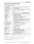
TB1: 8 Pin Input Terminal Description
Pin #
Description
1
Step Clock Input Anode (+): A positive going edge on this isolated input advances the motor by
one increment. The size of the increment is dependent on the Microstep Select Inputs of Switch 1.
2
Step Clock Input Cathode (-)
3
Direction Anode (+): This isolated input is used to change the direction of the motor. Physical
direction also depends on the connection of the motor windings.
4
Direction Cathode (-)
5
ON/OFF Anode (+): This isolated input is used to enable and disable the output section of the
driver. When HIGH (open), the outputs are enabled. However, this input does not inhibit the step
clock.
6
ON/OFF Cathode (-)
7
Fault Out (C): This is the collector of the optically isolated fault output. When NO fault occurs, this
output will conduct current into the emitter. Care must be taken to not pass more than 50mA of
current through this transistor.
8
Fault Out (E): This is the emitter of optically isolated fault output.
Table 2: Pin descriptions for input terminal block connector (TB1)
TB2: 3 Pin AC IN Terminal Description
Pin #
Description
1
AC IN: Hot
2
AC IN: Neutral
3
EARTH GROUND (Must be connected)
Table 3: Pin descriptions for input terminal block connector (TB2)
TB3: 5 Pin Input Terminal Description
Pin #
Description
1
Motor Ground
2
Phase 1A: Phase 1 of the Step Motor
3
Phase 1B: Phase 3 of the Step Motor
4
Phase 2A: Phase 2 of the Step Motor
5
Phase 2B: Phase 4 of the Step Motor
Table 4: Pin descriptions for motor terminal block connector (TB3)
Power Supply Requirements
The MLA10641 has an input line voltage ranging from 90-132VAC. TB2 pin 1 is used as the hot terminal
and is internally fused, TB2 pin 2 is used as the neutral terminal and TB2 pin 3 is the EGND terminal. The
EGND terminal must be connected.
**NOTE: The 10EMC1 Filter is required at the power input of the MLA10641 driver.
L010460
June 2012