1
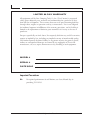
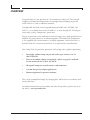
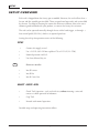
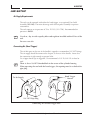
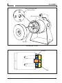
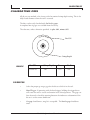
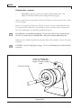
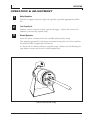
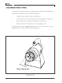
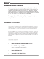
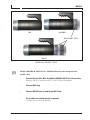
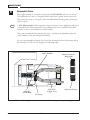
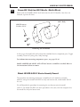
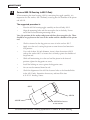
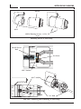
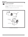
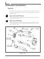
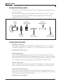
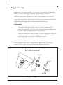
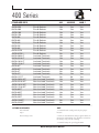
PICO
400 SERIES
SERVICE MANUAL
PREFACE
Copyright © by Pico Corporation, 2001.
All rights reserved. No part of this document may be reproduced, copied, transmitted,
stored in a retrieval system, or translated into any language in any form by any means
without the written permission of Pico Corporation.
Direct all inquires to:
Pico Corporation
444 Constitution Ave.
Camarillo, California. 93012
PH (805) 388-5510 • FAX (805) 482-4038
www.picotools.com • [email protected]
1st EDITION
• Dec, 2001
REVISED,
• Feb, 2003
ii
Model 400 Operations Manual
LIMITED 90 DAY WARRANTY
All equipment sold by Pico Crimping Tools Co. Inc. ("Pico" herein) is warranted
solely against defective parts, materials and workmanship for a period of 90 days
from the date of shipment. This warranty does not cover parts becoming defective
through abuse, neglect or operation contrary to instructions. Pico is not obligated
for incidental expenses in fulfillment of the warranty provisions, and its' liability is
limited to the replacement of defective parts returned to its' factory at the cost of
purchaser.
Except as specifically set forth above, Pico expressly disclaims any and all warranties,
express or implied by law, including any implied warranty of merchantable quality.
Pico further expressly disclaims liability to any person or entity for general, special,
indirect or consequential damages occasioned by any negligence of Pico in the
manufacture, sale, use, repair, maintenance or any handling of such equipment.
MODEL #
SERIAL #
DATE SOLD
Important Precautions
Air
For optimal performance & tool lifetime, use clean, filtered dry air
providing 70-120 PSI.
Model 400 Operations Manual
iii
PREFACE
Table of Contents
PREFACE
Table of Contents ............................................................................................... iii-viii
Overview ............................................................................................................ vi-viii
SETUP
Overview ................................................................................................................... 2
Air Setup ................................................................................................................3-4
Installing Locator....................................................................................................5-6
Installing Die ............................................................................................................. 7
Installing Cover nut ................................................................................................... 8
Calibrating Die .....................................................................................................9-10
Operation & Adjustment ......................................................................................... 11
Calibrating Tool....................................................................................................... 12
Troubleshooting ...................................................................................................... 13
MAINTENANCE
General Maintenance ............................................................................................... 16
General Overhaul ...............................................................................................16-17
Remove Cover nut/Die/Locator/Bench Mt. ..........................................................18-19
Set-Screw............................................................................................................20-21
Remove 400-18 Housing ......................................................................................... 22
Remove Toggle Assy ...........................................................................................22-23
Remove 400-5 Stop ............................................................................................22-23
Remove 400-2A Piston ............................................................................................ 24
Remove 400-1H Handle (Model 400 Only) ............................................................. 25
Booster Removal .................................................................................................25-28
400-1H handle from 400-1 Body............................................................................. 29
iv
Model 400 Operations Manual
Main Unit Assembly
400-1H handle to 400-1 Body (Model 400 Only).................................................... 30
400-30 Booster ...................................................................................................31-32
400-31 Piston .......................................................................................................... 32
400-29-1 Booster Cap ............................................................................................. 32
400-30 Booster (400-B-1)........................................................................................ 33
400-31-1 Piston....................................................................................................... 33
400-29 Booster Cap................................................................................................. 34
Toggle ..................................................................................................................... 34
400-2A Piston.......................................................................................................... 35
400-5 Stop............................................................................................................... 35
400-18 Housing .................................................................................................36-37
Sleeve and Bench Mt................................................................................................ 38
Component Assembly / Disassembly
Toggle Unit.........................................................................................................39-40
Piston Assembly....................................................................................................... 41
Cycling Valve........................................................................................................... 42
Hand Trigger ........................................................................................................... 43
Die Assembly........................................................................................................... 44
SPECIFICATIONS
Models................................................................................................................46-47
Applications .......................................................................................................48-49
Series 400 Parts lists ...........................................................................................50-62
Model 400 Operations Manual
v
PREFACE
Pico Model 400 Pneumatic Tool with Foot Pedal
vi
Model 400 Operations Manual
OVERVIEW
Congratulations on your purchase of a Pico Pneumatic Crimp tool. This versatile
crimping tool eliminates human effort in four/eight-indent crimping of pin and
socket contacts as well as solderless terminals.
Nonadjustable die heads, interchangeable between Models 400, 400 BHD, and
400-B -1, are available from stock to handle No. 26 wire through 4/0, all using the
same safety cycling “Crimpmaster” power unit.
Factory air pressure is now sufficient for even the largest sizes, made possible by the
addition of a power booster as standard equipment. The Model 400 Crimpmaster
is also supplied with a bench mount as standard equipment, and can be used as a
portable hand tool, a bench-mounted tool, or an optional foot controlled unit.
Pico Crimp Tools are precision, pneumatic, full cycling tools capable of producing:
•
Four/eight- indent crimps on pin and socket type contacts size 22
thru 350 MCM.
•
Four or two indent crimps on terminals, splices or pigtails, insulated
or non insulated size 26 thru 350 MCM.
•
Hexagonal crimps on coaxial contacts and connectors.
•
Custom designs for unique applications
•
Human engineered to prevent accidents.
This can be accomplished simply by changing dies and locators in accordance with
factory directions.
For further information on this product and other Pico products, please visit us on
the web at: www.picotools.com
Model 400 Operations Manual
vii
PREFACE
viii
Model 400 Operations Manual
Setup
SETUP
SETUP OVERVIEW
Each tool is shipped from the factory pre-assembled. However, the tool will not have a
locator and die assembly pre-installed. These are purchased separately and are installed
by the user. For help in choosing the correct die & locator solution, refer to the crossreference guide included with your product, or contact the factory for assistance.
The tool can be operated manually through the use of the hand trigger, or through a
foot control pedal (P/N 104), which is an optional purchase.
Setting the tool up for operation consist of the following:
SETUP
•
Connect Air supply to tool
•
Use a 1/4" ID, 3/8" OD line capable of 70 to 125 PSI (1-2 CFM).
•
Nominal pressure is 80 PSI.
•
Use clean, filtered, dry air
Note
Do not use an oiler
•
Install Locator
•
Install Die
•
Install Cover Nut
ADJUST • CHECK • RUN
•
Check Tool Operation - cycle tool with air, without inserting a wire and
contact to check operation of indentors
•
Gage Tool
•
Proceed with normal operation.
Detailed setup and operating instructions follow:
2
Setup
AIR SETUP
AIR SETUP
Air Supply Requirements
The tools can be operated with either the hand trigger, or an optional Foot Pedal
Assembly (P/N 104). The main advantage with the foot pedal assembly is operator
convenience.
The tools operate on air pressure of 70 to 125 PSI, (1-2 CFM). Recommended air
pressure is 80 PSI.
Note
Use clean, dry air with a quality filter and regulator installed within 25 feet of the
tool.
Do not use an oiler
Connecting Air (Hand Trigger)
The air inlet port on the rear of the handle is tapped to accommodate 1/4" NPT fittings.
The air supply should be connected to the port at the rear of the handle. Insure that
the connection is tight enough to prevent leaks.
Use of pipe thread tape is suggested. We recommend a 1/4" ID, 3/8" OD air hose be
used.
Note
There is also a 1/4 NPT threaded hole in the center of the cylinder housing.
When operating the tool with the hand trigger, this opening must be sealed with a
pipe plug.
Hand Trigger
Button
To Air Supply
1/4" NPT Pipe Plug
Connecting Air to Hand Trigger Port
Model 400 Operations Manual
3
SETUP
Connecting Air (Foot Pedal)
For foot pedal use, the air hose must be connected to the port in the center of the
cylinder.
The air hose connected to the tool cylinder is in turn connected to the outlet port of
the foot pedal. Connect the hose from the air supply to the inlet port of the foot pedal.
Note
For foot pedal use, the port in the rear of the handle must be sealed with a 1/4" NPT
pipe plug, and a plug must be installed in the exhaust port of the foot pedal.
Foot Pedal
Foot Pedal
Air Outlet Port
1/4" Pipe Plug
To Air Supply
1/4 NPT
Pipe Plug
for Exhaust port
From Foot
Pedal
Tool with Foot Pedal Connection
4
Setup
LOCATOR
INSTALLING LOCATOR
Remove the open ended cover nut (P/N 400-26) on the front of the tool housing.
Note
Tool is not shipped with die installed from factory - if die is installed, it must be
removed before locator can be installed.
Insert the locator into the retainer. (The retainer is the component thru which the
four drive arms protrude and which has an opening in the center which accepts the
locator).
Observe the notch in the shoulder of the locator. There is a corresponding pin in the
face of the counterbore in the retainer.
Orient the notch in the locator shoulder to coincide with the pin in the retainer. When
properly installed, the front of the locator shoulder will be flush with the retainer face.
Note
Never crimp without the correct locator in the tool. Contacts or terminals can fall
into the tool, causing the tool to jam and may cause damage to the unit.
Locator "Notch"
Retainer
Die Orient Pin
Locator "Notch"
Locator Orient Pin
Retainer
Locator Installed
Drive Arm
Installing Locator in Tool
Model 400 Operations Manual
5
SETUP
Locator Function
The function of the locator is to orient the contact in the die housing, such that the
contact barrel is directly in line with the die indentors.
This will result in a crimp meeting specifications for the particular contact being
processed.
The locator is matched to a specific contact & die configuration. Use of non-factory
specifications in this regard can result in a poor crimp and/or damage to the tool and
contact.
For help in choosing the correct die & locator solution, refer to the cross-reference
guide included with your product, or contact the factory for assistance.
Locator
Contact
Indentor
Cutaway view of locator and Die Assembly
INSTALLING DIE
Install the die set. There is an index pin in the face of the retainer. Observe the drilled
hole in the rear of the die housing. Orient this hole to fit over the index pin in the
retainer and press the die set into place. There will be some resistance when the four
drive arms come into contact with the indentors. The die set must sit flat on the
retainer face.
Note
6
Locator should be installed prior to installing die.
Setup
DIE ASSEMBLY
Rear View of Die and
Index Pin Hole
Die Orient Pin
Die
Retainer
Installing Die in Tool
Retainer
Die
Mounting Die - side view
Model 400 Operations Manual
7
SETUP
INSTALLING COVER NUT
When you have insured that the die set is flush with the face of the retainer-the cover
nut can then be installed.
Please note the “O” ring (P/N 6230-11) on the inside face of the cover nut. During the
process of crimping contacts and terminals, the contact or terminal will grow in length
with the displacement of material.The function of the “O” ring is to allow the die set to
move forward .040 as the contact is being crimped.
This prevents excessive side load being applied to the side of the indentors. Reduces
wear and prevents the contact from bending.
When installing the cover nut it should be installed with finger tip pressure only. Turn
the nut on until you feel the “O” ring come in contact with the die face.
Tightening the cover nut down excessively will prevent the “O” ring from performing
it’s intended purpose.
6230-11 O-Ring 400-26 Cover
Installing 400-26 Cover Nut
8
Setup
CALIBRATING DIE
CALIBRATING DIES
All die sets are marked at the factory with the nominal crimp depth setting. This is the
fully closed diameter when the tool is actuated.
The dies can be easily checked with Go-No Go gages.
A complete line of gages are available from the factory.
The tolerance, unless otherwise specified: is plus .002, minus .005.
A
414D -4N
Die P/N
.2 0 0
Crimp Depth
EXAMPLE
Die P/N
Crimp Depth
Go
No-Go
414DA-4N
.200
.195
.202
CALIBRATION
•
Select the proper go no-go gage for the die set which is in the tool.
•
Hand Trigger: If operating with the hand trigger, holding the trigger down
will cause the tool to actuate and remain in the closed position. The gage can
then be used to check the opening between the indentors to determine if the
die set is to the correct dimension.
•
Go gage should enter, snug fit is acceptable. The No-Go gage should not
enter.
Model 400 Operations Manual
9
SETUP
Calibrating Dies - continued
•
Foot Pedal: If operating with a foot pedal, hold the pedal down. The
indentors will then remain in the closed position for gaging.
If the Go gage does not enter freely into the Die, check to see that you have the correct
Go No-Go gage.
If the No-Go gage enters freely into the Die, in most cases this is indication that wear
has occurred to the indentors. Less probable is wear to the drive arms. Confirm that
the tool is within spec by calibration specified on page 12.
Note
The indentors are manufactured using S-7 tool steel, and are heat treated to Rc
56-58. As a result, they are should have a life span of many thousand cycles.
Indentors are available for purchase separately from a die assembly. Contact the factory
for details.
Note
CAUTION: Do not crimp against a gage. To do so will damage the tool and void the
warranty.
Prior to inserting Go
No-Go gage, Hold down
trigger to actuate crimp
cycle
Go No-Go Gauge
Gaging Tool
10
Setup
OPERATION
OPERATION & ADJUSTMENT
1
Adjust Regulator
With the air supply connected, adjust the regulator to provide approximately 80 lbs
PSI.
2
Test Crimp Cycle
3
Normal Operation
Without a contact and wire in place, operate the trigger. Observe the action of the
indentors to be sure they operate freely.
Insert the contact or terminal and wire assembly and proceed to crimp.
After operating personnel have become accustomed to using the tool, the air need not
be turned off while changing dies and locators.
If a die set fails to calibrate within an acceptable range, calibrate the tool following the
steps below to insure that the tool is within specification.
Contact inserted for crimp
Model 400 Operations Manual
11
SETUP
CALIBRATING TOOL
If a die set fails to calibrate within an acceptable range, calibrate the tool following the
steps below to insure that the tool is within specification.
•
To gage the tool remove the cover nut and die set.
•
Cause the tool to be actuated and held in the closed position. If using a foot
pedal, hold it down. If using the thumb button, hold it down.
•
Measure the distance between the face of two opposing arms.
This dimension should be: 1.985 to 2.003. If this is not the case, the arms are out of
alignment or worn. Contact the factory for replacement.
Measure from face to face
Dim = 1.985 to 2.003
Calibrating Tool
12
Setup
TROUBLESHOOTING
TROUBLESHOOTING
SYMPTOM: TOOL OPERATES SLUGGISHLY
1. Check the air supply to insure that there is a minimum of 80 P.S.I. provided
to the tool.
2. Check the air line size. It should be a 1/4" ID, 3/8" OD line.
If this does not correct the condition, the usual causes are:
• Worn "O" rings.
• A build up of debris and congealed lubricant.
• Misalignment of the booster cylinder piston rod in the B or B-1 models.
To correct any of the above, the tool must be disassembled. To disassemble, refer to
specific model instructions in the Maintenance chapter, or contact the factory.
SYMPTOM: TOOL CYCLES FORWARD, DOES NOT RETURN
•
The usual problem is the cycling valve (P/N 400-27A) This unit is mounted
in the face of the piston and the tool must be disassembled to replace it.
Follow the disassembly specified in the maintenance section. When the piston is
removed, check the valve to determine if the spring and "o" ring are functioning
properly. Replace if necessary.
•
Check the alignment of the booster cylinder rod.
Remove the booster cap (P/N 400-29) by screwing the cap counterclockwise. The
piston rod will now be exposed. Follow the directions on page ? to check alignment.
SYMPTOM: TOOL CRIMPS TOO LOOSE
•
If terminations are failing tensile or electrical tests:
Calibrate the die set per section, "Calibrating Die", pages 9.
Calibrate the tool, instructions found on the page 12.
SYMPTOM: TOOL CRIMPS TOO LOOSE
If the tool and die set calibrate properly, contact the factory to determine if the correct
die set is being used for the application.
Model 400 Operations Manual
13
SETUP
14
Setup
Maintenance
MAINTENANCE
GENERAL MAINTENANCE
The Pico model 400 series tools should be supplied with filtered, dry air. The tools
are thoroughly lubricated at the factory and if clean, filtered, dry air is provided, they
should not require additional lubrication for the first year. The tools are assembled
with the highest quality “O” ring lubrication, and should provide adequate lubrication
under normal conditions for the lifetime of the tool. If it becomes necessary to lubricate
the tool, Dow Corning DC-55 O Ring lubricant is recommended.
Factory personnel are available to advise on additional repair questions which may
occur. Additional information, including video files, are available at our web site www.picotools.com
GENERAL OVERHAUL
General overhaul for the unit can be accomplished by disassembling the tool into its
component parts, and after inspection, replacing parts as needed. Pico recommends
replacing all springs & O rings when performing any general overhaul to the tool.
For other problems such as a broken arm or a broken link in the Toggle assembly, it
is suggested that the tool be sent to the factory for repair. To produce a symmetrical
crimp, the face of the drive arms must be equidistant from the theoretical centerline.
When a new arm is replaced it may not match the other three due to wear which has
occurred.
DISASSEMBLY SEQUENCE
•
Remove Cover-nut, Die & Locator, Bench Mount (if installed)
•
Detach 400-18 Housing from 400-1 Body
Remove set-screw prior to 400-18 removal
16
•
Remove 400-TOG from 400-18
•
Separate 400-1H, 400-1 (Model 400 Only)
Maintenance
MODELS
400
400-BHD
BOOSTER UNITS
400-B-1
SERIES 400 MODEL TYPES
Note
Models 400-BHD & 400-B-1 have additional booster units not present on
models 400.
•
Remove Booster Units (Note: Only Models 400-BHD & 400-B-1 have Booster Units)
Remove 400-30 (2 units on 400-B-1), 400-31 Piston Assemblies
•
Remove 400-5 Stop
•
Remove 400-2A Piston Assembly from 400-1 Body
•
Disassemble (as needed) internal components
(Cycling Valve), Piston Assemblies
Model 400 Operations Manual
17
MAINTENANCE
MAIN UNIT DISASSEMBLY
General overhaul for the unit is accomplished by first disassembling the main unit, and
then (depending on need) disassembly of the toggle unit and piston assemblies.
Note
1
Models 400-BHD and 400-B-1 have additional booster unit(s).
Remove Cover Nut
Die
Remove by turning
counterclockwise. Die will now be
exposed.
400-26 Cover
2
Remove Die
Die Locating Pin
Remove die pulling (with hand
pressure) directly away from the
retainer, in a straight line.
18
Maintenance
REMOVING BENCH MOUNT
3
Remove Locator
Remove by pulling directly from
retainer.
Locator notch
Locator slot
4
Remove Bench Mount & Sleeve
Remove by first unscrewing the bench mount nuts. When removing the sleeve, it may
be necessary to spread it partway to remove.
Remove Nuts Remove Bench
Mount
Bench Mount
Sleeve - Note, it may
be necessary to spread
sleeve in order to
remove
Model 400 Operations Manual
19
MAINTENANCE
5
Note
Remove Set-Screw
The toggle assembly is attached to the piston rod (P/N 400-2B) with two set screws.
The innermost set screw is a dog point which locks into a groove on the piston rod.
The second set screw is a flat point and is installed behind the dog point and used to
lock it in place.
A 3/32 Allen wrench will be required to remove the two screws. Applying hard grease
to the end of the allen wrench will assist in keeping the screw attached to the allen
wrench so that it can be lifted out of the housing.
There are two methods for removing the screw - and these are dependent upon the
serial number for the unit being disassembled.
For each serial number sequence, first locate the rectangular slot in the bottom side of
the housing, P/N 400-18. (see diagram on following page)
400-7 Anchor
400-2B
Piston Rod
400-TOG
Toggle Assy
Inner Set Screw ~
Dog Point
Outer Set Screw
Set Screw
Side view showing location of setscrew in relation to piston assy and toggle
20
Maintenance
REMOVING 400-18 HOUSING
400-1
400-18
Slot in 400-18 for Access
to set screws
400-1H
Set-Screw Slot location - looking upside down at 400-18 & 400-1 housing
5A
Serial Number Tools 6200 and newer:
The set screw will be visible and accessible when the tool is in the retracted position. If
the set screw is visible, remove the locking set screw completely. Applying hard grease
to the end of the allen wrench will assist in keeping the screw attached to the allen
wrench so that it can be lifted out of the housing.
Next back out the dog point screw (approx. 4 complete turns) until you are sure that it
is no longer engaged into the piston rod.
5B
Serial Number Tools 6199 and older:
If the tool is an older model, the set screw may not be visible when the tool is in the
retracted position. With this condition, the tool must be caused to move to the closed
position.
Using Hand Trigger:
If using the push button to operate the tool, hold the button down - keeping the toggle
in its’ forward position. The set screw will now be visible through the 400-18 slot.
Remove set-set screw as described in previous section.
Using Foot Pedal:
If using the foot pedal to operate the tool, depress the pedal down keeping the toggle
in its’ forward position. The set screw will now be visible through the 400-18 slot.
Remove set-set screw as described in previous section 5A.
Model 400 Operations Manual
21
MAINTENANCE
400-18 Housing Screws
8/32 x 1/2"- 4 pcs
400-1
400-18
Removing 400-18 Housing
6
Remove 400-18 from 400-1 Housing
There are four 8/32 x 1/2" screws locking the 400-18 assembly into the main housing
400-1. Remove these screws and the 400-18 assembly can be pulled from the front of
the 400-1.
7
Remove 400-TOG from 400-18 Housing
There are four 10-32 x 5/16" dog point set screws locking the toggle assembly into the
main housing 400-18. Remove these set screws and the toggle assembly can be pulled
from the front of the 400-18.
Note
When reassembling, the set screw opening in the anchor, P/N 400-7, must be aligned
with the rectangular opening in the 400-18. See figure on page 21.
8
Remove 400-5 Stop from 400-1 housing
Remove the "C" ring, P/N 3100-354 using suitable snap ring pliers. This snap ring
holds down the 400-5 stop in place.
Note
22
The C ring is under considerable pressure. Remove with caution.
Maintenance
REMOVING 400-5 STOP
400-TOG Mounting Screws
10-32 Dog x 5/16" Point - 4 pcs
400-18
400-TOG Assy
Removing 400-TOG from 400-18
3100-354 C Ring
400-5 Stop
400-5 Stop
Removing 400-5 Stop
Model 400 Operations Manual
23
MAINTENANCE
Remove Piston Assembly from 400-1 Body - Model 400 Only
9
Withdraw the piston assembly from the 400-1. If the piston will not remove easily
with hand pressure, it may be necessary to use a pipe (.625 dia or smaller) inserted in
the rear to assist removal. See diagram. Use a soft rubber mallet and gently tap on the
pipe to remove the piston.
Note
For models 400-BHD & 400-B-1, it will be necessary to first remove the booster
units in order to insert the pipe. Go to step 11 on page 26.
400-2A Piston Assy
400-1 Body
Removing 400-2A Piston from 400-1 Body
400-1 Body
Piston Assy
.625" Pipe used to help
remove piston
Removing 400-2A Piston from 400-1 Body using .625" pipe
24
Maintenance
400-BHD & B-1 BOOSTER REMOVAL
10
Remove 400-1 Body from 400-1H Handle - Models 400 only
Remove the four 1/4-20 x 1-1/2" inch bolts from the 400-1H handle. Once these are
removed, separate the units.
400-1 Body
400-1H screws
1/4-20 x 1-1/2"
400-1H
Removing 400-1H Handle
At this stage, the model 400 tool has been disassembled into its component parts: Toggle
assembly, Piston & Cycling valve, body housings.
For information concerning components parts, see pages 39-44.
Models 400-BHD and 400-B-1 will still have booster assemblies attached. Refer to
the instructions below to remove
.
Models 400-BHD & 400-B-1 Booster Assembly Removal
The procedure for removing the booster assemblies for each model is essentially
identical, except that model 400-BHD has only one booster unit, while model 400-B-1
has two.
We will describe the procedure for removing the two booster units for model
400-B-1. For model 400-BHD, the basic procedure is the same, with the exception that
this model has only one booster unit.
Model 400 Operations Manual
25
MAINTENANCE
11
Remove 400-29 Booster Cap - Model 400-B-1
Turn the 400-29 booster cap counterclockwise to remove.
If the cap cannot be removed by hand, use a strap wrench to gain additional leverage.
Remove 400-29 Booster Cap
by turning Counter-Clockwise
400-1
Removing 400-29 Booster Cap (Model 400-B-1 shown)
12
Remove 400-31-1 Piston from 400-30 Booster - Model 400-B-1
There is a 1/4-20 thread in the center of the piston rod. With the 400-29 booster cap
removed, screw a 1/4-20 bolt into the rear of the piston rod. You will now be able to
pull the piston from the housing. It should move with minimal resistance.
400-31-1 Piston Assy
Model 400-B-1
1/4"-20 bolt inserted to
aide in piston removal
400-30 Booster
Removing 400-31-1 Piston Assy
26
Maintenance
REMOVE 400-29-1 BOOSTER CAP
13
Remove 400-30 Booster from 400-29-1 Booster Cap - Model 400-B-1
You will see four screws (1/4-20 x 1/2") which mount the booster cylinder (400-30) to
the 400-29-1 booster cap. Loosen these screws and remove the booster from the rear of
the booster cap.
400-30 Booster
1/4-20 x 1/2"
Cap Screws
400-30 Booster
400-29-1 Booster Cap
Removing 400-30 booster - Model 400-B-1 shown
14
Remove 400-29-1 Booster Cap
Model 400-B-1: Turn the 400-29-1 booster cap counterclockwise to remove.
Model 400-BHD: Turn the 400-29 booster cap counterclockwise to remove.
If the cap cannot be removed by hand, use a strap wrench to gain additional leverage.
Model 400-BHD
Model 400-B-1
400-29-1
Booster Cap
Turn Counter-Clockwise
to remove
400-29
Booster Cap
Removing 400-29-1 (or 400-29) Booster Cap
Model 400 Operations Manual
27
MAINTENANCE
15
Remove 400-31 Piston - Model 400-BHD & 400-B-1
There is a 1/4-20 thread in the center of the piston rod. With the 400-29-1 booster cap
removed, screw a 1/4-20 bolt into the rear of the piston rod. You will now be able to
pull the piston from the housing. It should move with minimal resistance.
400-1H
1/4-20 bolt used to aid in
piston removal
400 - 30
Booster
400-31 Piston
Assy
Removing 400-31 Piston Assy
16
Remove 400-30 Booster - Model 400-BHD & 400-B-1
There are four 1/4-20 x 1-1/2" screws securring the 400-30 booster to the 400-1H
handle. Remove these screws and seperate the two units.
400-1H
400-1
1/4-20” x 1-1/2”
Cap Screws
Remove 400-30 Booster
28
400-30
Booster
Maintenance
REMOVE 400-1H HANDLE
17
Remove 400-1 Body from 400-1H Handle
Once the four 1/4-20” x 1-1/2 inch bolts are removed in step 16, you can separate the
handle from the 400-1 body.
400-1H
400-1 Body
Removing 400-1H Handle
Disassembly of the unit is now complete.
For information on individual components and repair, see pages 39-44.
Assembly instructions begin on page 30.
Model 400 Operations Manual
29
MAINTENANCE
MAIN UNIT ASSEMBLY
Note
•
It is suggested that all "O" rings & springs be replaced prior to reassembly.
Refer to the parts list for your particular model included in the specification
section of this manual.
Note
•
Lubricate all O-rings prior to assembly. Dow Corning DC-55 "O" Ring
lubricant is recommended.
Note
•
There are two critical steps in reassembly of the 400 series pneumatic tools.
Careful attention should be placed to the alignment of the piston assemblies
including the piston assemblies that are contained in the booster units for
models 400-BHD & 400-B-1. An assembly guide tool, 400-1000, is available
for use in alignment of the cylinders. It is strongly recommend that this guide
be used. Alignment problems can cause cycling problems and/or damage to
the tool.
1
Attach 400-1H Handle to 400-1 Body - Model 400 Only
Note
Models 400-BHD & 400-B-1 go to step 2 on page 31.
Insert a new 6227-12 O-ring into the 400-1H handle.
Mount the 400-1H handle to the 400-1 Body housing using the four 5/16-18 x 1" flat
head cap screws.
Models 400 - go to step 9 on page 34.
400-1H
1/4-20 x 1-1/2"
Screws
400-1
6227-12 O-Ring
Installing 300-1H Handle to 400-1 body (Model 400 Only)
30
Maintenance
INSTALLING 400-30 BOOSTER
2
Mount 400-30 Booster to 400-1H and 400-1 - Model 400-BHD & B-1
Install new 6227-12 & 6227-28 O-rings in the 400-1H handle. Mount the 400-30
booster to the handle and the 400-1 body; install the four 1/4-20 x1-1/2” flat head cap
screws, leaving them loose.
400-30
Booster
6227-28 O-Ring
400-1H
400-1
1/4-20 x 1-1/2"
Screws - 4 pcs
6227-12 O-Ring
400-1H Side View
Attaching 400-30 Booster, 400-1H & 400-1 Body
3
Use Guide tool 400-1000 to align
The alignment of the booster to the main cylinder is critical. The cylinders must be
aligned so that the piston rods are on the same centerline. If there is misalignment,
the piston rod will bind and cause malfunction of the tool, or will reduce the force
available to complete the crimp.
Insert guide 400-1000 into the booster cylinder. Position the booster cylinder such that
the guide moves freely in the cylinder.
400-1000
Guide Tool
400-1H
400-1000
Guide Tool
400-30
Booster
Allen Wrench
Using Alignment tool with booster assembly
Model 400 Operations Manual
31
MAINTENANCE
3
Guide Tool - continued
4
Install 400-31 Piston Assembly - Model 400-BHD & B-1
Tighten the four flat head screws to a snug condition, test the movement of the guide
in the cylinder. If the guide does not move freely, reposition the booster cylinder until
it does.
Install the complete 400-31 piston assembly - consisting of 400-2A Piston, 400-31
Piston rod, 6227-42 O-ring. Install by inserting the assembly into the rear of the
400-30 booster until the unit is flush with the booster.
6227-42
O-Ring
400-30
Booster
400-31
Piston Assy
Installing 400-31 Piston in 400-30 Booster
5
Install Booster Cap (400-29 or 400-29-1)
Model 400-BHD: Screw on P/N 400-29 Cap and proceed to step 9 on page 34.
Model 400-B-1: Screw on P/N 400-29-1 onto the 400-30 booster.
Note
In both cases, insure that the P/N 6230-17 O ring is installed in the booster cap prior
to installing. P/N 400-29-1: Install new 6227-12 O-ring in Cap
Model 400-BHD
400-29
Booster Cap
400-29-1
Booster Cap
Model 400-B-1
6227-12
Difference between 400-29-1 & 400-29 Booster Caps
32
Maintenance
INSTALLING 2nd 400-30 BOOSTER
6
Install second 400-30 Booster - Model 400-B-1 only
Mount the booster to the 400-29-1 booster cap. Insert the four 1/4-20 x 1/2” flat head
cap screws, leaving them loose. Insert the 400-1000 guide tool, and tighten the cap
screws.
Allen Wrench
1/4-20 x 1/2"
Screws - 4 pcs
400-1000
Guide Tool
Tightening Second Booster Screws
7
Install 400-31-1 Piston Assembly - Model 400-B-1
Install the complete 400-31-1 piston assembly - consisting of 400-2A Piston, 400-31-1
Piston rod, 6227-42 O-ring and 400-27 Cycling valve. Install by inserting the assembly
into the rear of the 400-30 booster until the unit is flush with the booster.
6227-42 O-ring
400-31-1 Piston
Assy
Installing 400-31-1 Piston in Model 400-B-1
Model 400 Operations Manual
33
MAINTENANCE
8
Install Booster Cap 400-29 - Model 400-B-1
Install booster cap, P/N 400-29 and P/N 6230-17 O ring. The cap mounts onto the
400-30 booster, and is tightened by turning clockwise.
Booster installation for 400-B-1 now complete.
400-29
Booster Cap
Installing 400-29 Booster Cap
9
Install 400-TOG into 400-18 Housing - All Models
The following proceedures apply to all models, 400, 400-BHD & 400-B-1.
Mount the 400-TOG assembly into the 400-18 housing using four 10-32 x 5/32” half
dog screws.
10-32 x 5/16"
Dog Point Screws - 4 pcs
400-TOG
Assy
400-1
Installing 400-TOG into 400-18 Housing
34
Maintenance
INSTALL 400-5 STOP
10
Install 400-2A Piston Assembly into 400-1
Install 400-2A Piston assembly directly into 400-1 body. Insert until assembly is flush
with the rear of the 400-1 body and the front of the 400-1H handle.
400-2A
Piston
400-1
Installing 400-2A Piston Assy into 400-1 body - Model 400-B-1 shown
11
Install 400-5 Stop and C-clip
Install the 400-5 stop until it seats on the 400-2B piston rod.
Install the “C” ring, P/N 3100-354.
Note
C ring pliers are helpful in installing this item. This ring holds the front stop,
P/N 400-5 in place.
3100-554 C Ring
3100-354 C Ring
400-5 Stop
Installing 400-2A Piston Assy into 400-1 body - Model 400-B-1 shown
Model 400 Operations Manual
35
MAINTENANCE
12
Connect 400-18 Housing to 400-1 Body
When mounting the front housing, 400-18, containing the toggle assembly, it is
imperative that the anchor, 400-7 be firmly seated against the shoulder of the piston
rod 400-2B.
The suggested procedure is:
•
Place the 400-18 housing-toggle assembly on the tool body 400-1.
•
Align the mounting holes and the rectangular slot in the body. Do not
install the flat head housing mounting screws.
View the position of the anchor and piston rod thru the rectangular slot. There
should be no gap between the base of the anchor and the shoulder of the piston
rod.
•
Check to insure that the dog point set screw is in the anchor 400-7.
•
Apply air to the tool, causing the piston to come forward and remain in
that position.
•
Use a rod of about 3/4 inch diameter, insert it thru the retainer 400-11
and tap the anchor 400-7 to insure that it is firmly against the shoulder of
the piston rod.
•
While still maintaining air to the tool and the piston in the forward
position, tighten the dog point set screw.
•
Install the locking set screw against the dog point screw.
•
Air can now be removed from the tool.
•
Check the alignment of the 400-18 clearance holes to the threaded holes
in the 400-1 body. Reposition if necessary and install the four
8-32 X 1/2” housing screws.
400-1
400-18
400-1H
Slot in 400-18 for Access
to set screws
Set-Screw Slot location - looking upside down at 400-18 & 400-1 housing
36
Maintenance
INSTALLING 400-18 HOUSING
400-18
400-1
400-18 Housing Screws - 8-32 x 1/2"
4 pcs
Mounting 400-18 to 400-1 Body
400-2B Piston
Rod
Set-Screw
400-7 Anchor
400-7 Anchor
3/4" Rod
Side View - Mounting 400-18 Housing to 400-1 Body
Model 400 Operations Manual
37
MAINTENANCE
13
Install Sleeve and Bench Mount
Install the sleeve and bench mount.
At this stage, assembly is complete. Refer to the setup guide for operating
instructions.
For information on components, refer to the next section.
Sleeve
Bench Mount
Nuts
Bench Mount
Installing Sleeve and Bench Mount
38
Maintenance
COMPONENT DISASSEMBLY
Toggle Unit
Disassembly of the toggle unit consists of removing the links connecting the arm to the
yoke (400-7), and the front retainer, 400-11. Using the proper diameter drive punch
will aid in removal.
1
Remove Pins from 400-11 Retainer
Using a suitable punch, use light pressure to tap the pins out from the retainer. There
are 4 pins, 1/4 x 1-1/2" long.
2
Remove Pins from 400-10 Arm
Using a suitable punch (or cylinder rod), use light pressure to tap the pins out from
each 400-10 arm. Note, each arm is connected to a 400-9 Link. There are 4 dowel
pins, each is 1/4 x 1” long.
400-9
4 Pls
1/4” x 3/4”
4 Pls
1/4” x 1”
4 Pls
1/4 x 1-1/2”
4 Pls
400-7
10/32” x 5/16”
Dog Point SSS
400-11
10/32” x 3/16”
Cup Point SSS
400-10 H.D
4 Pls
Exploded Toggle
Model 400 Operations Manual
39
MAINTENANCE
Punch
400-7 Yoke
400-10 Arm
400-9 Link
1/4” x 1”
Removing 400-10 Arms
3
Remove Pins from 400-9 Link & 400-7 Yoke
Using a suitable punch, use light pressure to tap the pins out from each 400-9 link.
Note, each link is connected to the 400-7 yoke. There are 4 pins, each is 1/4 x 3/4"
long.
To reassemble: Reverse steps 1-3 from previous section.
Punch
400-7 Yoke
400-9 Link
Removing 400-19 Link from Yoke
40
Maintenance
Piston Assembly
1
Remove O Ring
Remove the 6227-42 O ring from the piston.
For booster piston assemblies, all use the same O-ring and piston - however the piston
rod P/N is different. Refer to the parts list for specific part numbers.
2
Remove Piston Rod
Generally there is no reason to remove the rod unless it needs to be replaced.
Unscrew the socket cap screw located at the rear of the piston rod. Next, unscrew
400-2B piston rod from the 400-2A piston by turning counterclockwise. Locktite is
used during initial assembly - it may be necessary to heat up the assembly if difficulty
unscrewing the piston rod from the piston is encountered.
To reassemble: Reverse steps 1-2. It is recommended that the “O” ring be replaced,
Pico recommends applying Dow Corning DC-55 “O” Ring lubricant prior to
reassembly.
Cycling Valve Assembly removal instructions in next section.
6227-42 O-Ring
400-2A
Piston
400-27A Cycling
Valve Assy
400-27A Cycling
Valve Assy
Socket Cap Screw
400-2B
Piston Rod
Piston Assembly
Model 400 Operations Manual
41
MAINTENANCE
Cycling Valve Disassembly
Remove 3100-37 retaining ring. Remove 400-27A Cycling Valve Assy from the rear of
the 400-2A Piston.
Extract the 400-28 alignment pin by pulling it out from the 400-27 valve. Typically,
the 156C spring will come when withdrawing the alignment pin. The remaining
components can now be removed.
400-27
Valve
400-275
Outer Spring
6227-08
O Ring
156C
Inner Spring
400-28
Alignment Pin
3100-37
Retaining Ring
Cycling Valve Assembly
Cycling Valve Assembly
Install 6227-8 O-Ring
Reassemble the cycling valve, starting first by installing a new 6227-8 “O” ring. Pico
recommends applying Dow Corning DC-55 “O” Ring lubricant prior to reassembly.
Install 400-275 outer spring
Install alignment pin
Insert the 400-28 alignment pin into the 400-27 valve. Prior to insertion, the 156C
inner spring should be placed over the alignment pin rod. There is a groove at the base
of the 400-27 body that the first coil of the 156C spring snaps into. Press the 400-28/
156C assembly in until the snap is heard to insure that these are firmly seated.
Install Cycling Valve
With “O” ring 6227-08 and outer spring 400-275 installed on the cycling valve body,
from the rear of the piston, insert the cycling valve assembly into the 400-2A piston.
Install 3100-37 retaining ring
Insert the 400-27A Assy into the 400-2A Piston from the rear. Apply pressure to the
head of the valve body and using c ring pliers, insert the retaining ring onto the cycling
valve, from the front side of the 400-2A Piston.
Installation is now complete.
42
Maintenance
Trigger Assembly
Malfunction of the trigger assembly is an extremely rare occurrence. If it becomes
necessary to remove the trigger components, the procedure is as follows.
Locate the .093 diameter roll pin in the handle on the exploded view of the tool.
Using a drive punch with a diameter less than .093 inch, punch out the roll pin. The
trigger housing and trigger slide can now be pulled from the handle.
To Reassemble:
•
Locate the roll pin groove in the trigger housing part number 400-17A.
Insert the trigger slide, 400-17B, into the housing aligning the milled slot in
the slide with the corresponding slot in the housing.
•
Insert the assembly into the tool handle. To assist in aligning the roll pin slot
with the opening in the handle it is suggested that a small diameter pin or
paper clip be used to check that the openings are in line.
•
Drive the roll pin into the handle
It may be helpful to first insert a roll pin from the opposite side. This will help
to ensure that the trigger is properly aligned while inserting the roll pin.
Roll Pin used on opposite side,
used as aide in installation
6227-07
6227-02
Roll Pin
400-17A
400-17B
Trigger Assembly
Model 400 Operations Manual
43
MAINTENANCE
Die Assembly
Note
The only reason to disassemble the Die is to replace worn indenters.
The indentors are manufactured using S-7 tool steel, and are heat treated to Rc 56-58.
As a result, they are should have a life span of many thousand cycles.
Indentors are available for purchase separately from a die assembly. Contact the factory
for details.
1. Remove the 8-32 set screw holding the 400-24 die cap, using an allen wrench.
2. Remove the 3100-250 C-Ring using C-ring pliers
3. Once the C-ring has been removed, you can remove the indenters.
Assembly is simply reversing steps 1-3.
400-24 Die Cap
3100-250 C-ring
400-14 Die
Body
Indentors
400-13-XXX*
4 Pcs
*The "XXX" refers to
a specific crimp depth,
which is application
specific
400-375 - 4 pcs
8-32 Allen
Point Screw
Die Assembly
44
Maintenance
Specifications
SPECIFICATIONS
400
400-BHD
400-B-1
46
Model 400 Operations Manual
Booster Cylinder
Booster Cylinders
MODELS
There are 3 basic models available in the 400 Series. The applications chart on the
following pages help to differentiate the models and their capabilities.
The basic difference between each model is determined by the addition of one or more
boosters. The 400 model does not come with a booster; the 400-BHD has one booster
unit, and the 400-B-1 has two booster units.
The booster unit(s) facilitate crimping larger diameter contacts.
An optional Foot pedal assembly for engaging the crimp cycle, P/N 104, is available for
purchase for all models.
AIR
For optimal performance & tool lifetime, use clean, filtered dry
air providing 70-120 PSI.
WEIGHT
400
400-BHD
400-B-1
14 lbs.
17 lbs.
21 lbs.
Model 400 Operations Manual
47
SPECIFICATIONS
APPLICATIONS
APPLICATIONS
400
400-B-1
400-BHD
22 thru 2
22 thru 4/0
22 thru 4/0
INSULATED
26-24 thru 6
26-24 thru 2
26-24 thru 1/0
UNINSULATED
26-24 thru 6
26-24 thru 2
22-18 thru 2/0
MAX. DIA.
MAX. DIA.
MAX. DIA.
CONTACTS
1.00
1.00
1.00
CONNECTORS
1.00
1.00
1.00
CONTACTS
PINS
SOCKETS
SOLDERLESS TERMINALS
COAXIAL APPLICATIONS
• Consult Factory on Specific Applications
NOTE: Applications listed above represent a small sample of connector applications serviced
by PICO Pneumatic crimping tools. If your particular application is not listed on page 48-49
contact the factory. By providing connector specifications, Pico can often produce a Die and
locator solution that will meet your needs.
48
Model 400 Operations Manual
400 Series
STANDARD DIES
414DA-22N
414DA-20N
414DA-16N
414DA-12N
414DA-8N
414DA-6N
414DA-4N
414DA-2N
414DA-0N
414DA-2/ON
414DA-4/ON-1
414DA-26-24-IT
414DA-22-18-IT
414DA-16-14-IT
414DA-12-10-IT
414DA-8IT
414DA-6IT
414DA-4T
414DA-2IT
414DA-1/O-IT
414DA-26-24-NIT
414DA-22-18-NIT
414DA-16-14-NIT
414DA-12-10-NIT
414DA-8NIT
414DA-6NIT
414DA-4NIT
414DA-2NIT
414DA-1/0-NIT
414DA-2/0-NIT
OPTIONAL ACCESSORIES
Foot Controls
Gages
Fitted Storage Cases
400
Pins & Sockets
Pins & Sockets
Pins & Sockets
Pins & Sockets
Pins & Sockets
Pins & Sockets
Pins & Sockets
Pins & Sockets
Pins & Sockets
Pins & Sockets
Pins & Sockets
Insulated Terminals
Insulated Terminals
Insulated Terminals
Insulated Terminals
Insulated Terminals
Insulated Terminals
Insulated Terminals
Insulated Terminals
Insulated Terminals
Non-Insulated Terminals
Non-Insulated Terminals
Non-Insulated Terminals
Non-Insulated Terminals
Non-Insulated Terminals
Non-Insulated Terminals
Non-Insulated Terminals
Non-Insulated Terminals
Non-Insulated Terminals
Non-Insulated Terminals
Yes
Yes
Yes
Yes
Yes
Yes
Yes
Yes
No
No
No
Yes
Yes
Yes
Yes
Yes
Yes
No
No
No
Yes
Yes
Yes
Yes
Yes
Yes
No
No
No
No
400-BHD
Yes
Yes
Yes
Yes
Yes
Yes
Yes
Yes
Yes
Yes
Yes
Yes
Yes
Yes
Yes
Yes
Yes
Yes
Yes
No
Yes
Yes
Yes
Yes
Yes
Yes
Yes
Yes
Yes
Yes
400B-1
Yes
Yes
Yes
Yes
Yes
Yes
Yes
Yes
Yes
Yes
Yes
Yes
Yes
Yes
Yes
Yes
Yes
Yes
Yes
Yes
Yes
Yes
Yes
Yes
Yes
Yes
Yes
Yes
Yes
Yes
NOTE:
1. Consult locator catalog or factory for proper
locators.
2. Tools are warranted for 90 days against defects in
material or workmanship but should be returned to
the factory every year for servicing.
3. Consult factory for special applications
Model 400 Operations Manual
49
400 Series Power Unit Parts List
Model 400-B-1
Model 400
Model 400-BHD
Page 50
Model 400 Cross-section View
400-1H
400-17A & 17B
400-27A Assembly
400-TOG
Toggle Assembly
6227-42
O-Ring
400-5 Stop
Die Assembly
400-2B Piston Rod
400-32
Spring
1/4-20 x 1-1/2
FHSCS - 4 Pls
6230-11
O-Ring
6227-28
O-Ring
400-2A Piston
3000-354
400-1
8-32 x 1/2 FHSCS
4 PLS
10-32 x 5/16
Dog Point SSS
400-26 Cover
10-32 x 3/16
Cup Point SSS
400-18
10-32 x 5/16 FHSCS
4 PLS
Page 51
Model 400 Exploded View
�������
�������
��������������
�������������
�������
������
�������
�������
�������
������
������
������
����������
������
������
�������
������
�����
����
����������
�����
�����
Page 52
�������
������
�����������
����
������
������
�����
��������
���� ��������������
�������������������������
�����
������
�������
�������
�������
������
������
�����
400-BHD Cross-section View
400-1H
400-17A & 17B
6230-17
O-Ring
6227-42
O-Ring
6227-28
O-Ring
6227-42
O-Ring
400-TOG
Toggle Assembly
6227-12
O-Ring
400-30
400-27A 400-5 Stop
400-32
Spring
400-2B
Piston Rod
Die Assembly
400-27A
400-2A
6230-11
O-Ring
400-29
400-31 Piston Rod
1/4-20 x 1-1/2
FHSCS - 4 Pls
400-1
3000-354
400-2A 8-32 x 1/2 FHSCS
4 PLS
10-32 x 5/16
400-26
Dog Point SSS
Cover
10-32 x 3/16
400-18
Cup Point SSS
10-32 x 5/16 FHSCS
4 PLS
Page 53
400-BHD Exploded View
6227-07
400-29
Rear Cover
6230-17
O-Ring
400-27A
Cyc Assy
1/4-20 x 1-1/2
FHSCS - 4 Pls
6227-02
400-30
Booster
400-17A 400-17B
6227-42
O-Ring
1/4-20 x3/8
SHCS
400-2A
Piston
400-2A
Piston
400-5
400-27A
Cyc Valve Assy Stop
400-31
Piston Rod
8-32 x 1/2 FHSCS
4 Pls
6227-12
O-Ring
400-1H
Handle
6227-28
O-Ring
400-1
Body
10-32 Half Dog x 5/16 SSS
FHSCS - 4 PLS
400-2B
Piston Rod
.040 SS
Washer
Page 54
6227-42
O-Ring
400-32
Return Spring
3000-354
Retaining Clip
400-18
Housing
400-TOG
6230-11
O-Ring
400-26
Cover Nut
400-B-1 Cross-section View
6227-42
O-Ring
6227-42
O-Ring
400-30
6230-17
O-Ring
6230-17
O-Ring
400-31-1
6227-42
O-Ring
400-TOG
Toggle Assembly
Die Assembly
400-30
400-27A
400-27A
6230-12
O-Ring
1/4-20 x 1/2
FHSCS - 4 Pls
400-17A & 17B
6227-12
O-Ring
400-29-1
400-29
6227-28
O-Ring
400-1H
400-31
400-1
1/4-20 x 1-1/2
FHSCS - 4 Pls
400-2A
400-5 Stop
3000-354
8-32 x 1/2 FHSCS
4 PLS
400-2B
400-32
Piston Rod
Spring
10-32 x 5/16
Dog Point SSS
10-32 x 3/16
Cup Point SSS
400-18
6230-11
O-Ring
400-26
Cover
10-32 x 5/16 FHSCS
4 PLS
Page 55
400-B-1 Exploded View
������
�����
�������
������
�������
������
�����������
����
�����
����
Page 56
��������
�����
�������
���������
��������
����������
������
������
�������
��������
�������
������
�������
������
�������
������
������
�������
������������
�����
�������
������
������
������
������ �������������
������
������
�����
����
�������
��������
�������
������
����������
�����
��������
��������������
������
����������
������
������
�������
�������
������
������
�������
�������
������� �������
��������������
�����
������
������
�������
������
�������������������������
�����
������
�������
�������
������� ������
������ ���������
400-TOG Toggle Assembly
( all models )
400-9
4 Pls
1/4” x 3/4”
4 Pls
1/4” x 1”
4 Pls
1/4” x 1-1/2”
4 Pls
400-7
10/32” x 5/16”
Dog Point SSS
400-11
10/32” x 3/16”
Cup Point SSS
400-10 H.D
4 Pls
Page 57
400-27A Cycling Valve Assembly
( all models )
400-27A Cycling Valve Assembly
400-2A Piston
400-2B Piston Rod
6227-08
400-27
Page 58
156C
Inner Spring
400-275
Outter Spring
7100-37
Retaining
400-28
Alignment Pin
Die Assembly
400-13 - *** 4 Pls
400-375 4 Pls
3100-250
400-24
400-14
*** Specific Indentor Part Number
is determined by the Die Application
Page 59
PARTS LISTS • MODEL 400 POWER UNIT
Part #
Description
Qty
.040 SS Washer
8-32 x 1/2 FHSCS
10-32 x 5/16 FHSCS
1/4-20 x 3/8 SHCS
1/4-20 x 1-1/2 FHSCS
400-1
400-1H
400-2A
400-2B
400-5
400-17A
400-17B
400-18
400-26
Washer
Flat Head Cap Screw
Half Dog SSS
Socket Head Screw
400-1H Screws
Body
Handle
Front Piston
Front Piston Rod
Piston Stop
Trigger Housing
Trigger Slide
Front Housing
Cover Nut
1
4
4
1
4
1
1
1
1
1
1
1
1
1
400-27A
Cycling Valve Assembly
1
Inner Spring
Cycling Valve Body
Outer Spring
Alignment Pin
O-Ring
Retaining Ring
1
1
1
1
1
1
Return Spring
Bench Mount
1
1
156C
400-27
400-275
400-28
6227-08
7100-37
400-32
400-BM
Page 60
Part #
Description
Qty
400-TOG
Toggle Unit
1
Dowel
Dowel
Dowel
Cup Point Screw
Dog Point Screw
Rear Anchor
Yoke
Heavy Duty Arm
Retainer
4
4
4
1
1
1
4
4
1
3000-354
6227-02
6227-07
Retaining Ring
O-Ring
O-Ring
1
2
2
6227-28
6227-42
6230-11
O-Ring
O-Ring
O-Ring
1
1
1
1/4 x 3/4
1/4 x 1
1/4 x 1-1/2
10-32 x 3/16 SSS
10-32 x 5/16 SSS
400-7
400-9
400-10-HD
400-11
PARTS LISTS • 400-BHD POWER UNIT
Part #
Description
Qty
Part #
.040 SS Washer
8-32 x 1/2 FHSCS
10-32 x 5/16 FHSCS
1/4-20 x 3/8 SHCS
1/4-20 x 1-1/2 FHSCS
400-1
400-1H
400-2A
400-2B
400-5
400-17A
400-17B
400-18
400-26
Washer
Flat Head Cap Screw
Half Dog SSS
Socket Cap Screw
Booster Body Cap Screw
Body
Handle
Front Piston
Front Piston Rod
Piston Stop
Trigger Housing
Trigger Slide
Front Housing
Cover Nut
1
4
4
1
4
1
1
2
1
1
1
1
1
1
400-TOG
400-27A
Cycling Valve Assembly
2
Inner Spring
Cycling Valve Body
Outer Spring
Alignment Pin
O-Ring
Retaining Ring
1
1
1
1
1
1
Booster Cap
Booster Body
Piston Rod
Return Spring
Bench Mount
1
1
1
1
1
156C
400-27
400-275
400-28
6227-08
7100-37
400-29
400-30
400-31
400-32
400-BM
1/4 x 3/4
1/4 x 1
1/4 x 1-1/2
10-32 x 3/16 SSS
10-32 x 5/16 SSS
400-7
400-9
400-10-HD
400-11
3000-354
6227-02
6227-07
6227-12
6227-28
6227-42
6230-11
6230-17
Description
Qty
Dowel
Dowel
Dowel
Cup Point Screw
Dog Point Screw
Rear Anchor
Yoke
Heavy Duty Arm
Retainer
4
4
4
1
1
1
4
4
1
Retaining Ring
O-Ring
O-Ring
O-Ring
O-Ring
O-Ring
O-Ring
O-Ring
1
2
2
1
1
2
1
1
Page 61
PARTS LISTS • 400-B-1 POWER UNIT
Part #
Description
Qty
Part #
Description
Qty
.040 SS Washer
8-32 x 1/2 FHSCS
10-32 x 5/16 FHSCS
1/4-20 x 1/2 FHSCS
1/4-20 x 3/8 FHSCS
1/4-20 x 1-1/2 FHSCS
400-1
400-1H
400-2A
400-2B
400-5
400-17A
400-17B
400-18
400-26
Washer
Flat Head Cap Screw
Half Dog SSS
Booster Body Cap Screw
Socket Head Cap Screw
Booster Body Cap Screw
Body
Handle
Front Piston
Front Piston Rod
Piston Stop
Trigger Housing
Trigger Slide
Front Housing
Cover Nut
1
4
4
4
1
4
1
1
3
1
1
1
1
1
1
400-32
400-BM
Return Spring
Bench Mount
1
1
Dowel
Dowel
Dowel
Cup Point Screw
Dog Point Screw
Rear Anchor
Yoke
Heavy Duty Arm
Retainer
4
4
4
1
1
1
4
4
1
400-27A
Cycling Valve Assembly
3
Inner Spring
Cycling Valve Body
Outer Spring
Alignment Pin
O-Ring
Retaining Ring
1
1
1
1
1
1
Retaining Ring
O-Ring
O-Ring
O-Ring
O-Ring
O-Ring
O-Ring
O-Ring
1
2
2
2
1
3
1
2
Booster Cap
Booster Cap
Booster Body
Piston Rod
Piston Rod
1
1
2
1
1
156C
400-27
400-275
400-28
6227-08
7100-37
400-29
400-29-1
400-30
400-31
400-31-1
Page 62
400-TOG
1/4 x 3/4
1/4 x 1
1/4 x 1-1/2
10-32 x 3/16 SSS
10-32 x 5/16 SSS
400-7
400-9
400-10-HD
400-11
3000-354
6227-02
6227-07
6227-12
6227-28
6227-42
6230-11
6230-17