1
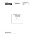
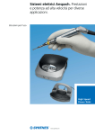
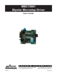
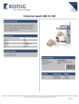
MDCKB1-120081-01
110VAC, 8A Brushless Controller
User’s Guide
A N A H E I M
A U T O M A T I O N
910 East Orangefair Lane, Anaheim, CA 92801
e-mail: [email protected]
L010776
1
(714) 992-6990 fax: (714) 992-0471
website: www.anaheimautomation.com
September 2012
MDCKB1-120081-01 Driver Features
•
•
•
•
•
•
•
•
•
•
•
•
•
Maximum Current Limit from 1.0-8.0 Amps (peak)
External 5K Potentiometer Speed Control
Internal Max and Base Speed Adjustment
2-Quadrant Operation
Hall Sensor Feedback
Constant Velocity Mode
Short Circuit Protection
Requires 90-120 VAC
Brake, Disable and Direction Inputs
TTL-CMOS Compatible Inputs
Compact Size (4.3”x3.6875”x1.41”)
Dual Mounting Option
Optically Isolated Analog Voltage Speed Control (optional)
General Description
The MDCKB1-120081-01 driver is designed to drive DC Brushless motors at currents of up to 8A
(peak) and 160V. The driver is protected against over current (cycle-by-cycle), hall sensor error and
under voltage. When an error occurs, a fault light is turned on to notify the user. Included on the
driver are internal potentiometers to control the maximum phase current allowed into the motor, the
maximum speed of the motor, and the base speed of the motor. An external potentiometer (5K) is
used to control the speed as well. The direction of the motor can be preset by the direction control
input. Other inputs to the drive include a run/stop and motor enable input. When using the run/stop
input, it overrides all other inputs into the driver. If the motor stalls, operation is halted and run/stop
must be toggled to have the motor run again.
Fault Protection
This driver is equipped with a FAULT LED to alert the user of the following conditions.
1. Invalid Hall Sensor Input code
2. Over Current. The driver is equipped with cycle-by-cycle current limiting
3. Undervoltage Lockout activation at 30VAC for the input voltage and 4.5VDC for Hall
Sensor power output voltage.
Caution: The MDCKB1-120081-01 driver does not have an internal fuse. To protect the
driver from major motor failures, an external fuse greater than the application maximum load current
is needed.
Ordering Information
Part #
Description
MDCKB-120081
110VAC DC Brushless Driver at 8A
MDCKB1-120081-01
110VAC Open Loop Only DC Brushless Driver at 8A
PWR-10EMC1
Dual Stage RF | Power Line Filter.
L010776
2
September 2012
Specifications
Control Inputs: (QD12, QD13, QD16-QD19)
External Switch Compatible
Run/Stop: I1 and I2 (QD12 and QD13)
Switch Open - Motor will not run and if running will decelerate rapidly
Switch Closed - Motor will run
Direction Control: D1 and D2 (QD16 and QD17)
Switch Open - Clockwise
Switch Closed - Counterclockwise
Enable Control: E1 and E2 (QD18 and QD19)
Switch Open - Motor is Enabled
Switch Closed - Motor is de-energized and will coast
Speed Adjustment Control: P1-P3 (QD9-QD11)
The external speed control potentiometer must be 5K Ohms.
P3 (QD9) - Pot (+)
P2 (QD10) - Pot Wiper
P1 (QD11) - Pot (-)
Note: If the motor stalls, adjust the speed control to operate faster than 0RPM and toggle run/
stop to have the motor run again.
Output Current Rating:
Adjustable 2.0 - 8.0 amperes per phase maximum operating peak current
(1.0 - 4.0 amperes per phase maximum operating continuous current)
Power Requirements: L1 and L2 (QD14 and QD15)
90VAC (min) - 135VAC (max)
Caution: The MDCKB1-120081-01 driver does not have an internal fuse. To protect the
driver from major motor failures, an external fuse greater than the application maximum load current
is needed.
Operating Temperature:
Heat Sink: 0° - 70°C
Hall Sensor Power Output:
6.25V @ 30mA maximum. Typical current draw from hall sensors is 20mA.
All three Hall Sensor inputs are pulled up through 20K ohm resistors.
Only the Motor Hall Power wire should be tied here.
L010776
3
September 2012
Commutation Sequence
Step
Step
1
2
3
4
5
6
1
2
3
4
5
6
Phase A
+
Z
-
-
Z
+
Phase A
-
Z
+
+
Z
-
Phase B
Z
+
+
Z
-
Phase C
-
-
Z
+
+
-
Phase B
Z
-
-
Z
+
+
Z
Phase C
+
+
Z
-
-
Z
Hall A
1
1
0
0
0
1
Hall A
1
1
0
0
0
1
Hall B
0
1
1
1
0
0
Hall B
0
1
1
1
0
0
Hall C
0
0
0
1
1
1
Hall C
0
0
0
1
1
1
120° Hall Spacing Sequence Forward
120° Hall Spacing Sequence Reverse
Step
Step
1
2
3
4
5
6
1
2
3
4
5
6
Phase A
+
Z
-
-
Z
+
Phase A
-
Z
+
+
Z
-
Phase B
Z
+
+
Z
-
-
Phase B
Z
-
-
Z
+
+
Phase C
-
-
Z
+
+
Z
Phase C
+
+
Z
-
-
Z
Hall A
1
1
1
0
0
0
Hall A
1
1
1
0
0
0
Hall B
0
1
1
1
0
0
Hall B
0
1
1
1
0
0
Hall C
0
0
1
1
1
0
Hall C
0
0
1
1
1
0
60° Hall Spacing Sequence Forward
60° Hall Spacing Sequence Reverse
+ = Top Transistor ON, Bottom Transistor OFF, Current Flows into this wire
- = Top Transistor OFF, Bottom Transistor ON, Current Flows out of this wire
Z = Top Transistor OFF, Bottom Transistor OFF, No current into or out of this wire (High Impedance)
Motor Connection
Refer to the hookup diagram for typical driver applications. When connecting a motor for the first
time, connect the hall sensor wires (5 of them) to the driver. DO NOT CONNECT THE PHASES
YET. Turn on power and rotate the motor by hand. If the RED FAULT LED turns on, the hall phases
are incorrectly wired. If the RED FAULT LED does not turn on, then the hall wires are connected
correctly. Power the unit down and proceed to connect the motor phases. If the motor does not run
or runs erratically, power down and check the speed potentiometer and make sure the phases are
connected correctly. There are only 6 different ways to connect the phase wires, and normally only
two will allow the motor to rotate, but only one is correct. If the direction of the motor is changed
and the no-load current of the motor is approximately the same and the motor runs smoothly in both
directions then the phase wires are correct. If the motor still runs erratically, adjust the close loop
compensation potentiometer R11.
The wiring of the motor phases should be separated from the hall and input connections to not allow
a possible source of interface.
L010776
4
September 2012
Open Loop Only Driver (MDCKB1-120081-01) Rated Motor Speed Range
Adjustment:
1. Set the external speed potentiometer to 50%. Set the minimum motor speed by adjusting
potentiometer R25 according to user application. The minimum running speed should be
set to a speed higher than 0RPM. The run/stop switch should be used to brake the motor
for 0RPM. If the motor stalls, adjust the speed control operate faster than 0RPM and toggle
run/stop to have the motor run again.
2. Slowly raise the external speed potentiometer to 100%
3. Set the maximum rated motor speed by adjusting potentiometer R17 according to user application. If R17 is set to the maximum setting and a slower speed is required, adjust R11
for slower maximum motor speed.
Note: A different speed range, maximum speed, or minimum speed can be attained by further
adjusting R17, and R25.
Motor Run/Stop
The motor run/stop feature allows the stopping of a motor by shorting out the bottom drives of the
three phases. Shorting QD12 and QD13 together allows the motor to run, while an open input
does not allow motor operation and if operating causes rapid deceleration.
Motor Direction
The motor direction feature allows the changing of the rotation of the motor. This input should
not be changed while motion is in progress. Shorting QD16 and Q17 together causes the motor
to turn in the CW direction, while an open between QD16 and QD17 causes the motor to turn in
the CCW direction.
Note: Avoid changing the direction of rotation when the motor is already running in any one direction.
The following instructions must be followed to prevent permanent drive failure due to over-current conditions that exist is dynamic
direction reversals of the motor:
1. Stop the motor by releasing the short on the Run/Stop input
2. Wait for at least 500mS
3. Change the direction with the DIRECTION input
4. Run the motor by shorting the Run/Stop input
Motor Enable
The motor enable feature allows the de-energizing of the motor phases. This input can be
changed while motion is in progress. Shorting QD18 and QD19 together causes the motor to
de-energize, while an open between QD18 and QD19 causes the motor to run at the given speed.
To run motor again.
Heating Considerations
The temperature of the heat sink should never be allowed to rise above 70 degrees Celsius. This
may occur with motor currents higher than 6A. If necessary, mount the unit to an additional heat
sink or air should be blown across the heat sink to maintain suitable temperatures.
L010776
5
September 2012
Terminal Descriptions
QD#
1
2
Board
Description
Designator
HP
HA
QD#
Board
Description
Designator
+4.0V (Pot Top)
Pot Wiper
12
I1
Brake 1
10
Hall Sensor A
13
I2
Brake 2
11
L1
Line HOT
3
HB
Hall Sensor B
4
HC
Hall Sensor C
15
L2
Line Neutral
5
HG
Hall Sensor (-)
16
D1
Direction 1
6
PA
Phase A
17
D2
Direction 2
7
PB
Phase B
18
E1
Enable 1
PC
Phase C
Motor Terminals
19
Description
9
Hall Sensor (+)
14
8
QD#
GND (Pot Bottom)
5K External Pot
E2
Enable 2
Input Terminals
Quick Disconnect Mating Connectors
For QD1-QD5, QD12-QD13, QD16-QD19:
Panduit # DNF18-110-M. Female Disconnect, nylon barrel insulated, funnel entry, 22 - 18 AWG,
.110 x .032 tab size.
For QD6-QD8, QD14-QD15:
Panduit # DNF14-250FIB-3K. Female disconnect, (standard receptacle housings), nylon fully
insulated, funnel entry with insulation support and internal wire stop. 16 - 14 AWG wire range,
.250 x .032 in. (6.3 x 0.8mm) tab size.
Quick Disconnect/Potentiometer Location
POT#
L010776
6
Description
R14
RAMP
R17
Max Speed
R23
Current Limit
R25
Min Speed
September 2012
Wiring Diagram
Dimensions
L010776
7
September 2012
COPYRIGHT
Copyright 2012 by Anaheim Automation. All rights reserved. No part of this publication may be reproduced,
transmitted, transcribed, stored in a retrieval system, or translated into any language, in any form or by
any means, electronic, mechanical, magnetic, optical, chemical, manual, or otherwise, without the prior
written permission of Anaheim Automation, 910 E. Orangefair Lane, Anaheim, CA 92801.
DISCLAIMER
Though every effort has been made to supply complete and accurate information in this manual, the
contents are subject to change without notice or obligation to inform the buyer. In no event will Anaheim
Automation be liable for direct, indirect, special, incidental, or consequential damages arising out
of the use or inability to use the product or documentation.
Anaheim Automation’s general policy does not recommend the use of its’ products in life support applications
wherein a failure or malfunction of the product may directly threaten life or injury. Per Anaheim Automation’s
Terms and Conditions, the user of Anaheim Automation products in life support applications assumes all
risks of such use and indemnifies Anaheim Automation against all damages.
LIMITED WARRANTY
All Anaheim Automation products are warranted against defects in workmanship, materials and construction,
when used under Normal Operating Conditions and when used in accordance with specifications. This
warranty shall be in effect for a period of twelve months from the date of purchase or eighteen months
from the date of manufacture, whichever comes first. Warranty provisions may be voided if products
are subjected to physical modifications, damage, abuse, or misuse.
Anaheim Automation will repair or replace at its’ option, any product which has been found to be defective
and is within the warranty period, provided that the item is shipped freight prepaid, with previous authorization
(RMA#) to Anaheim Automation’s plant in Anaheim, California.
TECHNICAL SUPPORT
If you should require technical support or if you have problems using any of the equipment covered by this
manual, please read the manual completely to see if it will answer the questions you have. If you need
assistance beyond what this manual can provide, contact your Local Distributor where you purchased the
unit, or contact the factory direct.
Note: The MDCKB1-120081 driver is not line isolated. Use only mechanical switches for the control inputs. The
terminals of motor connector contains high voltage. Do not probe any part of the driver with power on, this could
damage the drive or result in body injury.
ANAHEIM AUTOMATION
L010776
8
September 2012