1
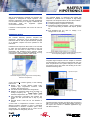
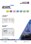
2820A C, L & Measuring bridge The Dielectric-Loss Analyzing System 2820a is designed for measurement of low dielectric losses and impedances (Dissipation Factor and Power Factor) of high-voltage apparatus (e.g. the insulation of bushings). The instrument works on the principle of a combined bridge-vector-meter and is capable of analyzing capacitive and inductive loads with high accuracy and stability. The Graphical User Interface of the instrument is highly intuitive, focussed on convenience with built-in useful programs (e.g. support tool for tuning the external highvoltage supply) and uses a large colour touch screen as the input device. The operator can choose between manual or automatic modes. While the manual mode provides quick measurements, the automatic test mode supports complete automated test sequences. Advanced software functionalities such as insulation temperature correction, programmable test sequences with pass/fail limits, graphical visualisation of measured data, etc. make this instrument a powerful tool for analysis of high-voltage equipment. The built-in industrial computer with standard interfaces (e.g. USB) enables easy exchange of measurement results, related settings, etc. for further analysis or reporting. FEATURES AND BENEFITS Accuracy capacitance 0.1%, tan -4 Additional signal analysis capabilities like Spectrum Analyser, Digital Scope and Data Logger are integrated Advanced, well-engineered test equipment, optimised to the specific application Compact, reliable and EMC hardened design Integrated solution with built-in industrial computer BENEFITS Easy to operate with Manual and Automated test modes, Software assisted test preparation, Execution and Trend analysis. Complete Measuring System including power supplies, standard capacitors, current comparators, test cells, application support and calibration from one supplier. Wide Application Range. Losses of all types of insulation including shunt reactors under unstable power frequency can be measured. Upgrade. Outdated Tettex bridge models (e.g. 2877, 2801, 2821, etc.) can be easily replaced, with existing cable sets. APPLICATIONS Turns ratio, voltage ratio, phase displacement and excitation current measurements according to ANSI, IEC and Australian standards on: Power Transformers Distribution Transformers Instrument Transformers Liquid or Solid Insulations Rotating Machines Generators Cables Capacitors Breakers Surge Arrestors Bushings Others 1/4 EASY OPERATION ANALYSIS FUNCTION With its self-explanatory graphical user interface this equipment is designed for simple operation. Test planning, preparation, execution and first assessment can be handled with just a fingertip. Additionally the touch-screen seals the equipment against environmental influences. The graphical display of measured data makes this instrument a powerful tool for analysis of high-voltage equipment. The analysis function can be used as follows: Comparison against limits (Pass/fail level) Trending Analysis (comparison over time) Comparison of different samples - Array of measuring curves corresponding to different test objects, phases etc. Free definable axis (e.g. tanδ vs. voltage, C vs. voltage, tanδ vs. time, etc.) If desired a USB keyboard and mouse can also be connected. SEQUENCE MODE The software efficiently performs complete test sequences. Sequences can be programmed in the instrument itself or with the optional software package on a separate computer and then uploaded to the instrument. Predefined test sequences allow tests to be executed by users who lack advanced knowledge of the test process. The test time for setup can be reduced significantly with definable pop-up graphics. These Pop-ups also help in reducing the likelihood of wrong connections or misinterpretation of test results. The Analysis screen with a list of stored measurements (top) and the corresponding diagram window (bottom) SIGNAL ANALYSIS Integrated signal analysis tools are helpful for research and development when sample measurements and type tests are performed. The system analyses curve forms, and spectrum show slow drifts and trending of the userselected measuring value. Spectrum Analyser Connection diagram picture (top) and the corresponding instruction text (bottom). Scope A test sequences consists typically of the following instructions: Setups: Type of DUT (Device Under Test), insulation type, temperature correction, serial numbers, test personnel, etc. Test levels: Set the desired test voltage levels Definition of measuring values to be recorded: e.g. Voltage, Frequency, tan Insulation Temperature, etc. Test instructions: Instructions with pictures can provide the test personnel with a step by step guide. Pass/fail levels: Limits can be set absolute or relative A Data base of temperature correction curves for different insulation materials is used to recalculate measurements to reference conditions (20°C, 68°F) automatically. The predefined set of curves can be easily expanded or changed by the user. Data Logger (trending) REPORTING All measurements including test object data are saved in XML & CSV format, which allows easy display, printing of test reports and transfer to database applications (e.g. with MS ACCESS™). 2/4 TECHNICAL SPECIFICATIONS Dissipation Factor (tan ) Power Factor (cos ) 1 Capacitance 2 Inductance 2 Test Voltage Test Current @ Input Cn Test Current @ Input Cx Test Frequency Apparent Power S 2 Real Power P 2 Reactive Power Q 2 Recorded Values 1 Measuring Time Measuring Channels Display Operating System Interfaces Data Format Operating Temperature Storage Temperature Humidity Protection classes, Standards Safety Specification Supply Weight WxHxD Range Max. Resolution Accuracy -5 -4 0 .. 100 1 x 10 1 % rdg 1 x 10 -5 -4 0 .. 1 1 x 10 1 % rdg 1 x 10 1 pF 0.01 pF 0.1 % rdg 0.1 pF 1000 kH 0.1 mH 0.2 % rdg 0.3 mH > 5V 5 1V 0.3 % rdg 1 V 20uA .. 300 mA 0.1 uA 0.3 % rdg 1 uA 20uA .. 15 A 0.1 uA 0.3 % rdg 1 uA 15 .. 1000 Hz 0.01 Hz 0.1 % rdg 0.1 Hz 1 mVA 0.1 mVA 0.5 % rdg 1 mVA 1 mW 0.1 mW 0.5 % rdg 1 mW 1 mvar 0.1 mvar 0.5 % rdg 1 mvar DF (tan), DF (tan)@20°C , DF (tan) [%], DF (tan) [%]@20°C , PF (cos), PF (cos)@20°C , PF (cos) [%], PF (cos) [%] @20°C , QF (quality factor), QF (quality factor)@20°C , CP (ZX= CP RP), RP (ZX= CP RP), CS (ZX= CS + RS), RS (ZX= CS + RS), LS (ZX= LS + RS), RS (ZX= LS + RS), LP (ZX= LP RP), RP (ZX= LP RP), Cn (Standard Capacitor Value), URMS, U/ 3, Ix RMS, In RMS, Im, Ife, Impedance Zx, Phase-angle (Zx), Admittance Yx, FrequencyTest, FrequencyLine, Apparent Power S, Real Power P, Reactive Power Q, Real [email protected], Real Power@10kV, TemperatureAmbient 3, TemperatureInsulation 3, Rel.Humidity 3, Temp.Corr.Factor K, Connection mode, Settings, Notes, Comments, Time, Date 0.3 sec / measurement @ averaging = 1 2 (Cn & Cx) 12” TFT, 800x600, integrated Touch-Screen Embedded Windows 4 x USB 1 x Ethernet 10/100 4 XML, CSV -10 .. 50°C -20 .. 70°C 5 .. 95 % r.h. non-condensing IP20, IEC 61010, CE mark, General IEC 61326-1, IEC 61000-4-X, 61000-3-X, EN 55011, ANSI/IEEE C37.90 VDE 0411/part 1a , IEC/EN 61010-1:2002 115VAC / 230 VAC selectable, 250VA, 50 / 60 Hz, PFC 21kg (47lbs) 48 x 27 x 44 cm (19” x 10.6” x 17.3”) 1 Accuracy values @ 50/60Hz ; THD of power source <10%; for detailed range dispersion and preconditions for accuracy values see user manual. 2 Range limit is given by test current and voltage of used power source 3 These values are measured with an external device (option). The values can be entered into the unit for temperature correction calculations and documentation purposes. 4 Allows communication respectively control of the unit 5 20uA/Cn .. 300mA/Cn SCOPE OF SUPPLY (ORDER CODE 3490064) C, L & tan Measuring Bridge 2820a Instrument Mains cable (country specific) Operating Instructions and Test Certificate For the connection cables please select desired type and length in “Accessories and Options” 3/4 ACESSORIES AND OPTIONS Order code Length Description 4841867 - Office Software package. Used for PC test preparation, data visualisation, staff education 4841882 Picture Field kit including: Rugged field cases for instrument, Rugged field cases for cables Complete connection cable kit for large DUT (e.g. power transformer) connection, including: Earthing cable with gripper, V-point connection cable (black), 1 measuring cable (blue) with clamps, 1 small clamp adaptor for measuring cables, Cn cable with plugs (orange) 4841880 4841881 10 m 20 m 4841868 4841870 4841871 4841869 4841872 4840206 4840041 4841873 4841876 4840207 4840168 4841877 4840186 2 10 20 xx m 2 10 20 xx m 2 10 20 xx m - 4840169 - Connection Lemo3 – clamp 107351 - 90° adaptor, Lemo3 – Lemo3 plug 4841895 OFFICES: Europe Haefely Test AG Birsstrasse 300 4052 Basel Switzerland + 41 61 373 4111 + 41 61 373 4912 [email protected] m m m m m m m m m Shielded Cx measuring cable (blue), Lemo3 – Lemo3 plugs Custom length on request (max. 50m) Shielded Cn cable (orange), Lemo3 – Lemo3 plugs Custom length on request (max. 50m) V-point guard cable (black) with lugs Custom length on request (max. 50m) Connection Lemo3 – alligator clip DUT Connection box Lemo3 – screw terminal China Haefely Test AG Representative Beijing Office 8-1-602, Fortune Street No. 67, Chaoyang Road, Chaoyang District Beijing, China 100025 + 86 10 8578 8099 + 86 10 8578 9908 [email protected] North America Hipotronics, Inc. 1650 Route 22 N Brewster, NY 10509 United States + 1 845 279 3644 + 1 845 279 2467 [email protected] HAEFELY HIPOTRONICS has a policy of continuous product improvement. Therefore we reserve the right to change design and specification without notice. 4/4