1
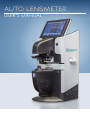
AUTO LENSMETER
USER’S MANUAL
MODEL#
ALM-411
USER’S MANUAL
Table of Contents
Warning and Cautions . . . . . . . . . . . . . . . . . . . . 3
Description of Lensmeter . . . . . . . . . . . . . . . . . . . 4
Safety Notes . . . . . . . . . . . . . . . . . . . . . . . . . . . . . . 4
Installation . . . . . . . . . . . . . . . . . . . . . . . . . . . . . . 4
Configuration . . . . . . . . . . . . . . . . . . . . . . . .
5
Parts Identification . . . . . . . . . . . . . . . . . . . . . . . . . . 5
Measurement Display . . . . . . . . . . . . . . . . . . . . . . . . . 6
Menu Display . . . . . . . . . . . . . . . . . . . . . . . . . . . . . 7
Operations Procedures . . . . . . . . . . . . . . . . . . . . 9
Preparation . . . . . . . . . . . . . . . . . . . . . . . . . . . . . . 9
Lens Setting . . . . . . . . . . . . . . . . . . . . . . . . . . . . . . 9
Lens Measurements . . . . . . . . . . . . . . . . . . . . . . . . . 11
Single Vision Lenses . . . . . . . . . . . . . . . . . . . . . . . . . . . . . 11
Mounted Lenses . . . . . . . . . . . . . . . . . . . . . . . . . . . . . . . 11
PD Measurement . . . . . . . . . . . . . . . . . . . . . . . . . . . . . .
12
Contact Lenses . . . . . . . . . . . . . . . . . . . . . . . . . . . . . . .
13
Bifocals/Trifocals . . . . . . . . . . . . . . . . . . . . . . . . . . . . . . . 14
Progressive Power Lenses . . . . . . . . . . . . . . . . . . . . . . . . . . 16
Prismatic Lenses . . . . . . . . . . . . . . . . . . . . . . . . . . . . . . . 18
Marking the Optical Center . . . . . . . . . . . . . . . . . . . . . . . . . . 19
UV Transmittance Measurement . . . . . . . . . . . . . . 20
Specifications . . . . . . . . . . . . . . . . . . . . . . . . 21
Maintenance . . . . . . . . . . . . . . . . . . . . . . . . 22
Replacing Printer Paper . . . . . . . . . . . . . . . . . . . . . . . . 22
Replacing Fuses . . . . . . . . . . . . . . . . . . . . . . . . . . . 22
Cleaning Exterior . . . . . . . . . . . . . . . . . . . . . . . . . . . 22
Accessories . . . . . . . . . . . . . . . . . . . . . . . . . 24
USER’S MANUAL
Warnings & Cautions
Norwood Device & Diagnostics is not responsible for the safety and reliability of this
instrument when:
• Assembly, disassembly, repair, or modification is made by unauthorized dealers or
persons.
• Instrument is not used in accordance with this User’s Guide.
WARNING: AN INSTRUCTION THAT DRAWS ATTENTION TO RISK OF INJURY OR DEATH.
WARNING: ANY REPAIR OR SERVICE TO THE ALM-411 MUST BE PERFORMED BY EXPERIENCED PERSONNEL OR
DEALERS WHO ARE TRAINED BY NORWOOD DEVICE & DIAGNOSTICS SO THAT CORRECT OPERATION OF THE ALM411 IS MAINTAINED.
WARNING: THIS INSTRUMENT IS NOT SUITABLE FOR USE IN THE PRESENCE OF FLAMMABLE ANESTHETIC
MIXTURES, SUCH AS OXYGEN OR NITROUS OXIDE.
CAUTION: AN INSTRUCTION THAT DRAWS ATTENTION TO THE RISK OF DAMAGE TO THE PRODUCT.
CAUTION: DO NOT REMOVE THE OUTSIDE COVERS OF THE UNIT OR ATTEMPT TO REPAIR ANY INTERNAL PARTS.
REPAIR AND SERVICE OF THE UNIT MUST BE PERFORMED BY EXPERIENCED PERSONNEL OR DEALERS WHICH ARE
TRAINED BY NORWOOD DEVICE AND DIAGNOSTICS.
CAUTION: MAKE SURE THAT THE VOLTAGE APPLIED TO THE UNIT IS THE SAME AS THE VOLTAGE WHICH IS GIVEN
ON THE DATA PLATE NEXT TO THE INPUT CORD RECEPTACLE OR DAMAGE TO THE UNIT MAY OCCUR.
CAUTION: DO NOT USE SOLVENTS OR STRONG CLEANING SOLUTIONS ON ANY PART OF THIS INSTRUMENT AS
DAMAGE TO THE UNIT MAY OCCUR. SEE MAINTENANCE SECTION FOR DETAILED CLEANING INSTRUCTION.
CAUTION: USE OF ALCOHOL ON THE LIQUID CRYSTAL DISPLAY (LCD) MAY CAUSE DAMAGE TO DISPLAY. SEE
MAINTENANCE SECTION FOR DETAILED CLEANING INSTRUCTION.
CAUTION: THIS INSTRUMENT IS NOT SUITABLE FOR USE IN THE PRESENCE OF FLAMMABLE ANESTHETIC MIXTURES
SUCH AS OXYGEN OR NITROUS OXIDE.
CAUTION: THIS INSTRUMENT HAS ELECTROSTATIC DISCHARGE SENSITIVE DEVICES (ESDS) WHICH ARE SENSITIVE
TO STATIC HIGH VOLTAGES STORED IN AND TRANSFERRED BY THE HUMAN BODY. OBSERVE CORRECT ESDS
PRECAUTIONS OR PREMATURE MALFUNCTION OF THIS INSTRUMENT WILL OCCUR.
CAUTION: THIS INSTRUMENT MUST BE PLUGGED INTO AN OUTLET WITH AN EARTH GROUND WHICH IS CONNECTED
TO THE RECEPTACLE OR DAMAGE TO THE UNIT MAY OCCUR. DO NOT DISABLE OR REMOVE THE GROUND PIN.
CAUTION: THE POWER CORD IS THE DISCONNECTING DEVICE FROM THE ELECTRICAL POWER SOURCE. DO NOT
POSITION THE INSTRUMENT SO THAT IT IS DIFFICULT TO OPERATE OR DISCONNECT THE POWER CORD FROM THE
POWER SOURCE.
3
3
USER’S MANUAL
Description of the Lensmeter
Description
This Auto Lensmeter is used for measuring single vision lenses, bifocal (trifocal) lenses,
progressive power lenses (PPL), and contact lenses (CL).
The display screen utilizes a full-graphic LCD, displaying measured values of right-eye
and left-eye lenses at one time and graphically showing the alignment condition in the
shape of a target.
The menu is simple and clear. Icons are conveniently located on the screen with touch
screen built-in UV tester.
Safety Notes
• Be careful when you carry the instrument, strong shock may damage the unit.
• Make sure to place the instrument on a level and stable place.
• Avoid using the instrument in a place that is exposed to direct sunlight or near
incandescent light.
• Do not use the instrument in the following environment:
Below Temperature: 41°f | Above Humidity: 80%
• Clear the instrument regularly in order to make the measurement work accurately.
After use, turn off the power and cover with dust cover.
• Be sure that the nose slider is on the left of the instrument.
• If you hear any abnormal sounds coming from the unit, turn off the unit and contact
distributor.
Installation
• Check to be sure that all accessories are included in packaging.
• Connect power cord to the power inlet at the back of the instrument and then at the
wall outlet.
4
USER’S MANUAL
Configuration
Parts Identification
• Read Button: Button for reading data. This makes the measured data on the display
fixed so it will be saved in memory.
• Protective cap: Used as a dust cover, remove before measuring and replace when
done.
• Nosepiece: Used to place the lens on the base point for measurement. When
measuring contact lenses (CL), replace this with the special CL nosepiece.
• Lens Holder Lever: Used to move the lens holder. To fix the lens, lift once and lower
it gently. To remove the lens, lift it until it clicks.
• Nose Slider: Used to measure PD of spectacles. When the nose pads of the spectacles
are placed astride, it automatically detects the lens sides and calculates the distance
between the right and left ‘read’ positions as the PD value.
• Pilot Lamp: Power ON when lit.
• Marking Lever: Used for marking lenses. Put spectacles in place then lower the lever
to mark lenses.
• Lens Table Lever: Used to move the lens table back and forth.
• Printer: Used to print measured data.
• UV cover: UV measuring part cover.
• NOTE: The display will automatically turn OFF when not in use for a period of time.
The auto OFF time limit can be changed in the MENU DISPLAY. To turn unit back ON,
press any button.
5
5
USER’S MANUAL
Configuration
Measurement Display
Setting Signs
0.01, 0.12, 0.25
Steps
+/-, +,-
CYL reading direction
30.40.50.60
Abbe value
Target
Shows the measuring point while lens is on the nosepiece. The shape of
the target changes with alignment.
O
Out of center
+
In the center within 0.5
+
Aligned to the center (marking point)
R/L sign
Appears when the lens side is specified, and values below each show the
measured data of the side.
“S” sign
Shows that the measured lens is single.
PD values
Show both monocular PD (LPD,RPD) and total PD of spectacles.
6
USER’S MANUAL
Configuration
Menu Display
7
7
USER’S MANUAL
Configuration
Menu Display (continued)
8
USER’S MANUAL
Operations Procedures
Preparation
• Connect the power cord to the power inlet.
• Connect the power cord to the wall outlet.
• Turn on the power.
• NOTE:
• Do not turn on the power with the lens on the nosepiece. If the lens is on the
nosepiece, a ’DATA ERROR’ message will appear on the measurement display.
Remove the lens and turn on the power again.
• The same will happen if the protective cap is on nosepiece, take it away and try again.
• Check if the nose slider is on the left end. If not, a ‘PD ERROR’ appears.
Lens Setting
Specify the lens side
• When you don’t need to measure PD values,
make sure the nose slider is flipped to the
left. Press L\R button to specify right-eye or
left-eye lens.
• When measuring PD, the position of the nose
slider will be taken for the R\L judgment and
R\L button reoperation will be ignored. It can
measure LPD, RPD or the distance between
the optical centers.
Continued on page 10 »
9
9
USER’S MANUAL
Operations Procedures
Lens Setting (continued)
Set the lens
• Place the measuring lens on the nosepiece with the convex side up
Fix the lens
• Place the measuring lens on the nosepiece with the convex side up.
10
USER’S MANUAL
Operations Procedures
Lens Measurement
Measuring Single Vision Lenses
• Bring the target to the center. Move the lens to
bring the target ‘O’ close to the center of the
alignment circle.
• When the target comes within a range of 0.5 ∆ from
the center, the shape of the target changes to a
cross line. Moving the lens to align the target, the
shape of the target changes to a large cross. There
are two ways to measure.
• Pressing the read button, the measured data
will be fixed. Pressing +/- alternates the cylinder
reading direction. Pressing the clear button, the
measurement will repeat again.
• When the ‘AUTO READ’ parameter is set, data will
be automatically fixed after the target is centered.
Just as the read button is pressed to repeat the
measurement, press the ‘Clear’ button first, perform
alignment and press the ‘Read’ button again.
Measuring Mounted Lenses
REGULAR MEASUREMENT
• Press ‘L/R’ button, bring the target to the center.
Move the lens to the target ‘O’ close to the center of
the alignment circle. When the target comes within
a range of 0.5 ∆ from the center, the shape of the
target changes to a cross line, move the lens to align
the target ‘O’ to the center cross so that the shape
of the target changes from a cross line to a large
cross. Press the read button and the measured data
will be fixed.
• Press L/R button, measure the other lens, and
repeat the same steps as the first lens.
11
11
USER’S MANUAL
Operations Procedures
Lens Measurement
PD Measurement
Alternate L/R lens by moving nose slider.
• Move the lens table until it touches the button of the frame and move nose slider to
the center of mounted lenses.
• Move the lens to bring the target close to the center of the alignment circle. When
the target comes within a range of 0.5 ∆ from the center, the shape of the target
changes to a cross line.
• Move the lens to align the target to the center cross, so that the shape of the target
changes from a cross line to a large cross.
• Pressing the ‘read’ button, the measured data will be fixed.
• Measuring the other lens, repeat the same steps as the first lens.
• Press Print Button to Get Value.
12
USER’S MANUAL
Operations Procedures
Lens Measurement
Measuring Contact Lenses
1. Change the nosepiece to the CL
nosepiece for contact lens.
2. Establish the CL measurement
mode as shown.
3. Set the CL.
4. Align the target.
• Place the lens on the nosepiece with
the convex side up. NOTE: Hold the
CL with tweezers. Be careful not to
damage the lens, only use tweezers
with round tips.
5. Press the ‘read’ button.
6. Press the ‘mode’ button, the mode
returns to the normal measurement
mode.
NOTE:
• Measure the contact lens as quickly as possible so that the lens surface does not
become dry.
13
13
USER’S MANUAL
Operations Procedures
Lens Measurement
Measuring Bifocals or Trifocals
1. Bring the distance part onto the nosepiece.
2. Measuring the distance power.
• After the shape changes from a circle to
a cross line, press the ‘read’ button. The
measured data distance will be fixed.
3. Measuring the addition power (ADD)
• Pulling the lens toward you to bring near
portion onto the nosepiece, press the ‘add’
button.
• The ADI appears on the display, when the
shape changes from a circle to a cross line,
press the ‘read’ button.
• The measured data for near portion will be
fixed.
• For bifocals, the measurement is completed at
this point.
• For trifocals, go to the next step on next page.
14
USER’S MANUAL
Operations Procedures (continued)
Lens Measurement (trifocals continued)
1. Bring the near portion onto the nosepiece.
• Press ‘add’ button. AD2 appears on the display.
• After the shape changes from a circle to a cross line, press the ‘read’ button.
• The measured data for near portion will be fixed
15
15
USER’S MANUAL
Operations Procedures
Lens Measurement
Measuring Progressive Power Lenses (PPL)
• Pressing Mode change button, the PPL
measurement mode will be established.
Measuring uncut lenses.
• Using the manufacturer’s specific eye
point marks, the lens should be placed
with its horizontal marks paralleled to
the table. The near position is inside.
ADD and the measured data appear in
the display. Bring the distance part onto
the nosepiece, then move the lens slowly.
Measuring mounted lenses
• Set the lens.
• Bring the distance part onto the upper
third of lens.
• Bring the target to the guideline. Move
the lens sideways to bring the target into
the middle of the guideline. When the
target changes to a cross (+) or +, press
‘read’ button, the distance is fixed.
16
USER’S MANUAL
Operations Procedures
Lens Measurement
• Use manual or automatic memory for measuring
distance.
• When the ‘Push’ sign appears, move the lens
according to arrow direction. It will start to measure
the progressive region. Meanwhile, the screen
demonstrates the ADD hestogram.
• Search for the point where the ADD degree
changes, when it is at maximum value, press the
‘memory’ button and finish the measurement.
NOTE:
When gradually moving lens, uncut lens’, nearsighted
,partial edge, or farsighted partial edge, some lens
prisms may be too big, surpassing the instrumental
measuring scope.
If this happens the instrument will demonstrate ‘over
prism’. Move the lens toward the middle.
The ADD of some lenses consequently increases,
sometimes out of the range of near portion.
If this happens, the biggest ADD is the range of near
portion.
Press the ‘read’ button when the icon appears in the
near portion.
17
17
USER’S MANUAL
Operations Procedures
Lens Measurement
Measuring Mounted Prismatic Lenses
• To mark the pupil center, instruct the customer
to wear the spectacles and look straight.
Then mark the pupil center on each lens.
NOTE:
The mark should be smaller than 1mm in diameter.
Anything bigger may interfere with the measurement.
• Specify the lens side. Press L/R button to specify
right eye lens or left eye lens.
• Choose the prism indication type
• Rectangular coordinates ∆ :
I 5.00 D0.03
• Polar coordinates ∆ :
1.00°
• Set the lens by placing the lens on the nosepiece as
shown with the convex side up.
• Fix the lens with the lens holder.
• Bring one of the eye point marks to the center of
nosepiece.
• Press the ‘read’ button.
18
USER’S MANUAL
Operations Procedures
Lens Measurement: Step 3 (continued)
Marking the Optical Center
This is the method used to mark the lens in order to specify the optical center and the
horizontal direction for mounting it to a frame.
• Move the lens more to align the target to the center cross so that the shape of the
target changes from a cross line to a large cross.
• Set the axis to the prescribed value. While watching the axis value on the display,
rotate the lens until the value shows the prescription. If the large cross changes back
to a cross line, align again.
• Set the prismatic lens to the prescribed value, press the ‘menu’ button and make the
prismatic value the same as the prescribed prism value.
• Choose rectangular coordinates. ’O’ means base out, ‘I’ means base in, ’D’ means
base down and ‘U’ means base up.
• Put the measuring lens onto lens table, rotate it gently and make the direction the
same as the prescribed value.
• Press the marking lever down to mark the lens. Three points in a line parallel to the
lens table will be marked.
• To remove the lens, raise the lens holder lever until it clicks.
NOTE:
• Do not touch the markings as the ink is easy to smear.
19
19
USER’S MANUAL
UV Transmittance Measurement
Measurement Process
• Turn on power.
• Take out the UV measuring part cover.
• Press UV button.
• Set the lens on the place of the
UV measuring part.
• The measurement appears in the screen.
NOTE:
• When no lens in place, UV transmittance
rate is 100%.
• If not, wipe the two windows of measuring
box with a dry cloth.
• Do not place the lens inside the measuring
part before pressing UV button.
• It will automatically close after two minutes
when you do not use the UV measurement
after pressing UV button.
• In order to protect and save the life of UV
measuring part, please close this function after measuring lens.
20
USER’S MANUAL
Specifications
ALM-411 Specs
Measure Scope
Sphere
0~±25D(0.01/0.12/0.25D steps)
Cylinder
0~±9.99D(0.01/0.12/0.25D steps)
Axis
0~180(1° step)
Addition
0~±9.99D(0.01/0.12/0.25D steps)
Prism
0~15 (0.01/0.12∆/0.25∆ steps)
Measurement Mode
Measuring Mode
Lens Auto Recognition
Contact Lens
Pupil Distance
45~90mm, 0.25mm steps
Cylinder
+, -, +/-
Prism
X-Y, P-B
Measuring Speed
0.1 second
Lens Diameter
¢ 20~108mm
Contact Lens
Soft/Hard Lens
Display
5.6" LCD/TFT
Print
Thermal Printer
Power Supply
100~240V 50/60HZ 25W
Dimension
222*161*372mm3
Package
530*330*370mm
Weight
Approx. 6KG
21
21
USER’S MANUAL
Maintenance
Replacing Printer Paper
1. The cover opens by pressing the ‘O’ mark on the top of the cover.
2. Hold up the green control stick.
3. Make sure the paper is not jammed, but cut cleanly.
4. Set the new printer paper, if needed.
5. Pass the printer paper through the paper outlet of the printer cover head, down the
green control stick, and close the cover.
Replacing Fuses
If the instrument does not turn on, the fuse may have blown.
Replace them with the spare fuses provided.
1. Turn off the power.
2. Disconnect the power cord from the wall outlet.
3. Remove the fuse holder.
4. Replace the fuses.
5. Set the fuse holder back into position.
Cleaning Exterior
• When the exterior parts of the instrument become dirty, wipe with a soft, dry cloth.
• For stubborn dirt, immerse the cloth in a neutral detergent, wring well and wipe.
• Finally, wipe off with a soft, dry cloth.
CAUTION:
• Never use an organic solvent such as paint thinner to clean the instrument as it may
ruin the surface of the instrument.
22
USER’S MANUAL
Maintenance
Cleaning protective glass
• For optimal product performance, clean dust and dirt from the protective glass
underneath the nosepiece on a regular basis.
• Lift up to remove the nosepiece and clean the protective glass.
• Blow off any dust on the glass with a blower brush.
• If it is still dirty, wipe gently with a lens cleaning paper.
Ink Refilling
When markings become faint, please refill the ink box.
NOTE:
• Do not drop to other spots, if so, please use a cotton
ball dipped in alcohol to clean.
23
23
Accessories
Contents of ALM-411
1. Printer paper
6. Nose-piece
2. Spare fuses
7. Nose-piece (for contact lens)
3. Dust cover
8. User’s manual
4. Glasses cloth
9. Ink
10. Power cord
5. Protective cap
11. PC Cable
(1)
(5)
(2)
(3)
(6)
(4)
(7)
(8)
(9)
( 10 )
( 11 )
DISTRIBUTED BY:
NORWOOD Device & Diagnostics
1 North Morton Ave. 2nd Floor
Morton, PA 19070
WWW.NORWOODVISION.COM | 855.370.1900