1
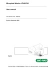
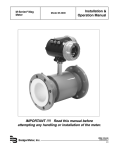
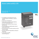
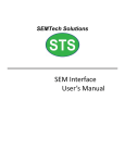
Manual for making TEM samples using FIB 1. Open the Zeiss SmartSEM software 2. Check the vacuum status of the System (normally below e-‐6), Gun (should be e-‐10 ) and Fib gun ( e-‐9). Before you work on your sample a). If you are going to deposit Pt, open the FIB Control panel and check the reservoir and capillary to heat the Platinum source. 3. To load a sample; a). put your sample into one of the sample holders which one depends on the application. b). Make sure all guns (EHT and Fib) are off . c). Select Store/Recall from the Stage drop down menu. When the new window opens select “$Exchange”. This will reset the stage to the proper position for loading the sample. d). Open the Airlock software panel e). Select Vent f). Open load-‐lock door and load sample holder, close door and select “Store” g). Once the chamber has evacuated select transfer, when the valve opens insert the sample and secure it to the microscope stage. Retract the sample loading rod into the locked position then select “Store” h). When the valve has closed select “Resume” 4. Find the eucentric point a). Check EHT value in the Data Zone to verify the voltage value. Change if necessary. b). Turn on the chamber view camera and raise the height of your sample using the Z adjust. About half the distance between the current location and the bottom of the column. c). Switch to the SE2 or InLens detector and focus on your sample. d). In the Stage tab window select Track Z. d). Using the Z stage adjust raise (or lower) your sample to give 10 -‐12 mm of working distance. e). In the Aperture window select Beam Shift then select “O” f). Increase the magnification to to 5k~10k, the focus and stigmate the image. g). Press the wobble button and adjust aperture alignment using aperture X and Y knob. h). Go to view tab, check crosshair and use joystick to move the reference point into the center. Tilt the stage to 1 degree, use M+ and M-‐ button to move the reference point back into the center of the crosshair or on the same horizontal line. Then go back to 0 degree, move stage to make the reference point back into the center again, then repeat tilting stage to 1 degree and changing M+ and M-‐, till the reference point is located in the center at both 1 degree(the same horizontal line is also ok) and 0 degree. Then repeat the process at 5 degree, and then repeat this at 54 degree, until the eucentric point is found. 4. Find the coincidence point a). Open the FIB control window and turn the fib gun on, wait till the current box turns green and the value goes to 2.0μA. b). In the FIB Control window go to Align tab, select “Beam Shift” and zero (R on the right bottom of the beam shift box). c). Raise the stage carefully using joystick for Z adjust until the working distance (WD in the data zone) goes to 5mm, your reference point should still be there. (never let anything touch the bottom of the pole piece) d). Press F8 to switch SEM mode to Fib mode, use joystick carefully to adjust Z value to move the reference point into the center of the crosshair , make sure the working distance is still 5mm when using joystick. Then press F8 to switch Fib mode back to SEM mode, use beam shift to move the reference point into the center of the cross hair in SEM mode. Coincidence point is found. 5. Outgas the GIS system (CHECK WITH JOHN DUNLAP BEFORE OUTGASING THE GIS) a). Shut off EHT and FIB gun. b). Open the Gas Injection Control window, then within that window select Outgas. c). Close the SEM column valve and Fib gun valve, d). Start outgas process. e). After outgas is done, when the System vacuum is back in the e-‐6 open SEM column valve and close the outgas window. f). Turn EHT and Fib gun back on, the fib gun valve would open automatically. g) Focus image in both SEM and FIB and the working distance is 5mm. 6. Deposition of protection layers on the area you want to make TEM sample. This step is not necessary for all samples. It is best done at low electron beam voltage EHT 2KV and using High Current mode a). Insert the nozzle in GIS control window. b). In SEM mode use the Reduced area raster to select an area for deposition, 15~20mm is fine. Select scan speed 6 then check open valve box in GIS control window, on the left of temperature reservoir box, after about 1min, uncheck the valve box . You should see a thin film of Pt on the surface where the beam was scanning. 7. Deposition of Platinum layer for TEM sample prep a). Press F8 to switch to FIB mode. If your sample is easily damaged by the FIB beam freeze the image after a single scan. b). Select Fine Rectangle form the FIB selection window and draw a rectangular box on the protected area. The size should be in the range of 12-‐15μm*2μm (you can choose the size as you need). Then go to shape tab in FIB control window, choose deposition mode, frequency X = 20000, frequency Y = 1. You can use current below 30KV-‐200pA, Gas ID = Platinum, and waiting time should be 15s or more to have a uniform Platinum atmosphere before depositing. Deposition time is variable but generally 2-‐4 minutes are required. Then click Clear list and Add, and Mill to begin the deposition. The deposition thickness should be around 1μm, it depends on your deposition time and current, you can balance them to get 1 μm deposition. c). Measure the thickness of the deposition, in SEM mode, select Tilt Rotate from the menu options and select Tilt Compensation. Enter a value of 54° as tilt compensation angle (NOT tilt angle) and use |μ| to measure the thickness. You can do this while depositing to get the right thickness and stop depositing anytime by clicking □ in mill tab. After deposition is done, retract the nozzle. 7. Cut a lamella a). In FIB mode, draw three trapezoids, one below and one above the deposition layer, and one to the left of the deposition layers. The lower and upper trapezoids should be at the edge of the Pt layer as shown in the following figure. The upper trapezoid is generally larger than the lower one to allow better visibility of the bottom of the lamella during cut out. b). With the lower trapezoid selected choose mill for depth in the FIB shape tab, the parameters could be width = 10 μm, height = 10μm, depth = 10 μm, number of layers =3, mill current = 30kV, 2nA, for materials you should choose what materials you are cutting. Then click clear list and add. Repeat the selection process for each trapezoid except only Add do not Clear when adding them to the milling list. The trapezoid on the left only needs to be cut to about half the depth of the top and bottom cuts. You can see the total milling time and if ready select Mill. c). After initial milling begin coarse polishing. For the down side polishing, the stage will need to be tilted to 55 or 56 degrees, and for the up side tilt the stage to 52 or 53 degrees. After tilting select Fine Rectangle from the FIB Tools menu and define a small rectangle just larger than the milled edge. For the first pass use current = 30kV, 500pA. After polishing both sides of the lamella reposition the Fine Rectangles and mill a second time with a current = 30kV, 200pA. Continue this process until the lamella is approximately 500nm thick. 8. Lamella Cut Out a). Tilt the stage to 0 degree, then cut the lamella from two sides and bottom as shown below. It is sometime beneficial to tilt the sample to -‐5 degrees to allow one to see the bottom of the lamella a little better b). Select Fine Rectangle from the FIB Tools menu and define a small rectangle on the left side of the lamella. In the FIB menu select Mill for Depth, select depth of a few microns, select the milling material and the probe (typically 30kv, 500pA, then Clear and Add to the milling list. Repeat the process for the bottom of the lamella and the right side. The left side and the bottom should be cut completely, for the right side leave a bar at the top of the lamella between the lamella and the bulk sample. This will hold the lamella while attaching the lift out needle. 9. Use the Kleindiek tool to lift out the lamella a). Zoom out the image to the lowest magnification in both SEM and FIB mode, turn mag lock off and reduce the SEM mag as low as possible. It is best to also have the Chamber View open on the right computer monitor. b). It is also safer to lower the stage Z axis to a working distance of 10mm or so before inserting the needle b). Turn on kleindiek, and set the speed to S5 or S6. S6 gives VERY LARGE movement of the needle so if using S6 make very small changes. Always move the needle DOWN before moving IN. During the approach process, you need to switch between TV mode, Aux mode, SEM mode and FIB mode continuously to check the position of the needle. As you continue to approach the lamella you need to check the position of the needle in both the SEM and FIB image. At the lowest magnification in the SEM image the needle should appear from the left side of the image, in the FIB image the needle should appear from the bottom of the image. c). The SEM image is best used for Left/Right and In\Out positioning. The FIB image is best for Up/Down (Z) positioning. c). Insert the GIS nozzle before your needle is too close to the lamella because inserting nozzle causes a slight shake of the stage which might make your needle hit and possibly destroy the lamella. d). After inserting nozzle, move the needle using S3 or S2 until the tip just touches the lamella (it is best to open the gas flow valve on the GIS before the final approach of the Kliendeik needle). In the FIB mode select Fine Rectangle from the FIB Tools and draw a rectangle which covers both the tip and the lamella. In the FIB Menu select the Shapes tab and set the system up for Deposition (use parameters: Current 10pA, Time 120seconda). Switch the FIB imaging probe to 10pA and make sure the image is focused. Deposit platinum on this region to weld the needle to the lamella. Figure bellow shows the process. e). After welding, CLOSE THE GIS VALVUE then retract the nozzle, then make the final cut of the lamella f). Use the kleindiek to lift the lamella out. Use S3 or S2 to move the needle carefully, it is easy to break the weld. Start by moving the lamella Up Once you have raised the lamella above the cut out area you can use joystick to lower the stage. The lamella is successfully lifted out and ready to be weld to the copper grid. 9. Weld the lamella on the copper grid a). Lower the stage to a safe position (working distance between 10~15mm would be fine). Move the copper grid right below the pole piece, then rotate the stage to make the copper grid parallel to the bottom line of the imaging window, also you have to make sure the curving part of the grid is facing downward and the flat part is facing upward. It is best to raise the kliendeik needle up so the working distance is less than 5mm so when the stage is raised it will not hit the needle. b). Focus on the tallest part of the grid then slowly move the stage up to the eucentric point (5mm working distance), check the focus as you raise the stage. Then find the coincidence point. c). Move the lamella carefully towards the tip of the copper grid, during this process, you will need to switch from SEM to FIB mode back and forth to check the position and distance between the lamella and grid. If your SEM image and FIB image are off,you can either move the stage in FIB mode or use beam shift in SEM mode for a better observation of your lamella. But never use beam shift in FIB mode and do not move the stage in the SEM mode. When the lamella is close to the grid , cut a flat surface out on the copper grid. It should be a very small depth into the grid, the purpose of this cut is to provide better contact between the lamella and the grid. If it is too deep, your whole sample would be buried in the hole and you wouldn’t have space to do final polishing. d). Begin to move the lamella closer to the grid. While it is still several microns away insert the GIS nozzle. Then continue to slowly move the lamella until it contacts the grid or is very close. Before the lamella contacts the grid go ahead and open the GIS valve. Make the final move then draw a rectangle which covers the lamella and the grid, and weld this part using deposition mode (as above 10pA and 120 seconds)). e). After welding, close the GIS valve and retract the nozzle. Then cut the Kliendeik needle from the lamella and move the needle to a safe position using S3 and S4 and do some sharpen cutting to the needle tip for the convenience of next user, then move the needle back to the original position behind the pole piece using larger steps like S5 or S6. Final thickness of the polished sample should be 50 – 100nm. At an SEM EHT of 5kv a sample will appear transparent (with SE2 detector) when it is ~100nm thick. At 3kv the sample will appear transparent in the SE2 image when it is 50 – 60nm thick. The SE2 detector can be used to evaluate thickness and the In-‐lens detector can be used to evaluate roughness of the final polish. 10. Final polishing a). Tilt the stage to 54 degree, the top of the lamella with the platinum bar will be facing you and you cut through this direction. b). Tilt the stage to 56 degree, then cut a window using low current like 30kV, 50pA or 30kV, 20pA. Then tilt to 52 degree and cut a window on the opposite side of the lamella. The lamella should be 200nm or 300nm thick after this polishing. It is best at this stage to mill out a window such that the bottom of the lamella is not milled, this will help maintain the rigidity of the sample. c). Change the SEM EHT voltage to 3kV and use a lower FIB current such as 10kV, 20pA. The FIB milling and Imaging voltage need to be the same. So if you are going to polish with 10kv or 5kv be sure to switch the imaging current also. After each mill check the SEM image for transparency. Once the sample is close to the desired thickness more delicate polishing may be needed to protect the sample. For the FIB set the voltage to 5kv and current to 20pA, tilt the sample to 50 degrees, define the milling window using a fine rectangle. For milling, select Deposition Mode and set the X frequency to 5,000 (instead of the usual 20,000) and the time to 30 seconds and mill (NO GAS). When finished change the tilt to 58 degrees and mill again in deposition mode. 11. Take your sample out and log off a). Shut off FIB gun, tilt the stage to 0 degree and use joystick to lower the stage to a safe position, then shut off EHT. Pull out Recall/store manual, click home, and the stage would go back to home position and ready to be taken out. If you are not going to use GIS for like the whole weekend, you can uncheck temperature reservoir and capillary boxes, if you or someone else is using it tomorrow, you can leave the them on. b). Check all the vacuum status and valves, and make sure everything is right condition. Then click vent, after venting is done, open the chamber door and take your sample out. c). Close the chamber door, hold it for a little while and click pump, check the vacuum is going down, then log off.