1
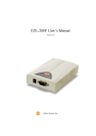
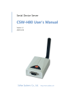
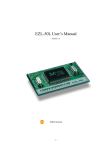
EZL-400S User’s Manual
Version 1.1
Sollae Systems Inc.
-Table of Context 1.
OVERVIEW..................................................................................................................... - 4 -
1.1.
OVERVIEW ......................................................................................................................- 4 -
1.2.
COMPONENTS..................................................................................................................- 5 -
1.3.
SPECIFICATIONS ..............................................................................................................- 5 -
1.3.1.
Power ............................................................................................................................ - 6 -
1.3.2.
Dsub Connector ............................................................................................................ - 6 -
1.3.3.
Network Interface.......................................................................................................... - 7 -
1.3.4.
LED Interface................................................................................................................ - 7 -
1.3.5.
Console S/W .................................................................................................................. - 8 -
2.
INSTALLATION AND TEST RUN ............................................................................... - 9 -
2.1.
INSTALLATION METHOD ..................................................................................................- 9 -
2.1.1.
Checking the Communication Environment.................................................................. - 9 -
2.1.2.
Connecting to the Network.......................................................................................... - 10 -
2.1.3.
Configuring the Environmental Variables ................................................................... - 10 -
2.2.
TEST RUN......................................................................................................................- 10 -
2.2.1.
Changing PC IP Address............................................................................................. - 10 -
2.2.2.
Installing EZL-400S .................................................................................................... - 10 -
2.2.3.
Connecting to Serial Port of PC.................................................................................. - 10 -
2.2.4.
Communication Test .................................................................................................... - 11 -
3.
CONFIGURING ENVIRONMENTAL VARIABLES................................................ - 12 -
3.1.
CONFIGURATION WITH EZCFGMP ...................................................................................- 12 -
3.1.1.
Local Search................................................................................................................ - 12 -
3.1.2.
Remote Search............................................................................................................. - 13 -
3.1.3.
The differences between LOCAL SEARCH and REMOTE SEARCH .......................... - 14 -
3.1.4.
Configuring with ezcfgmp ........................................................................................... - 14 -
3.2.
CONFIGURATION BY CONSOLE ......................................................................................- 19 -
3.2.1.
Entering the Console of EZL-400S.............................................................................. - 19 -
3.2.2.
Menu Structure ............................................................................................................ - 20 -
4.
THE OPERATION MODE OF EZL-400S.................................................................. - 22 -
4.1.
NORMAL COMMUNICATION MODE ...............................................................................- 22 -
4.2.
CONSOLE MODE............................................................................................................- 22 -
5.
NORMAL COMMUNICATION MODE .................................................................... - 23 -
-2-
5.1.
T2S ...............................................................................................................................- 23 -
5.1.1.
Communication ........................................................................................................... - 23 -
5.1.2.
Connection Termination and Keep Alive Function...................................................... - 23 -
5.2.
ATC ..............................................................................................................................- 24 -
5.3.
COD .............................................................................................................................- 25 -
5.3.1.
Communication ........................................................................................................... - 25 -
5.3.2.
Connection Termination and Keep Alive Function...................................................... - 25 -
5.3.3.
Reconnection ............................................................................................................... - 25 -
5.4.
U2S...............................................................................................................................- 26 -
6.
ATC MODE ................................................................................................................... - 27 -
6.1.
OVERVIEW ....................................................................................................................- 27 -
6.1.1.
AT command format .................................................................................................... - 27 -
6.2.
BASIC AT COMMAND SET (EXAMPLE: ATA, ATD ETC.) ................................................- 27 -
6.3.
EXTENDED AT COMMANDS (EXAMPLE: AT+PLIP ETC.) ...............................................- 28 -
6.4.
ONLINE STATE AND ONLINE COMMAND STATE .............................................................- 28 -
6.4.1.
Changing Online State to Online Command State ...................................................... - 28 -
6.4.2.
Changing Online Command State to Online State ...................................................... - 28 -
6.5.
EXAMPLE OF TCP CONNECTION ...................................................................................- 29 -
6.5.1.
Example of Active Connection .................................................................................... - 29 -
6.5.2.
Example of passive Connection................................................................................... - 29 -
6.6.
EXAMPLE OF TCP DISCONNECTION ..............................................................................- 29 -
6.6.1.
Example of active disconnection ................................................................................. - 29 -
6.6.2.
Example of passive disconnection............................................................................... - 30 -
7.
TECHNICAL SUPPORT, WARRANTY, AND NOTES ON OPERATION............. - 31 -
7.1.
TECHNICAL SUPPORT ....................................................................................................- 31 -
7.2.
WARRANTY ..................................................................................................................- 31 -
7.2.1.
Refund ......................................................................................................................... - 31 -
7.2.2.
Free Repair Services ................................................................................................... - 31 -
7.2.3.
Charged Repair Services............................................................................................. - 31 -
7.2.4.
Notes on Operation ..................................................................................................... - 31 -
8.
REVISION HISTORY .................................................................................................. - 33 -
-3-
1. Overview
1.1.
Overview
Along with the development of the Internet, the demand for data communication
functions has increased recently. Data communication over the Internet requires using
TCP/IP, the Internet communication protocol. That is to say, in order to connect a
system to the Internet, TCP/IP protocol must be implemented. It is possible to
implement TCP/IP by directly implementing the protocol, porting public TCP/IP, or
using Operating System (OS). However, all these methods impose burdens on the
developer in time, cost, and technology.
ezTCP series, a Serial ↔ TCP/IP protocol converter product group of Sollae Systems,
enables you to use TCP/IP communication (the Internet communication) function simply
by “connecting the cable to a serial port”. ezTCP sends data from the serial port to the
Internet network after TCP/IP processing, and vice versa.
EZL-400S in ezTCP product group is a product that provides TCP/IP communication
through wired or wireless LAN. In other words, like other ezTCP products, EZL-400S
sends data from the serial port to the wired or wireless LAN after TCP/IP processing and
vice versa.
EZL-400S has 4 RS232 ports.
It provides not only DHCP but also PPPoE, so that it can be applied to the cable network
and the xDSL network.
As EZL-400S provides SSL security function, it can be used in a system that requires a
high level of security.
-4-
1.2.
Components
z
EZL-400S Body
z
5V Power Adopter (Option)
z
RS232C cable for PC connection (Option)
z
PCMCIA Card (Option)
1.3.
Specifications
Power
Input Voltage
5V (±10%)
Current
500mA typical
Dimension
190mm x 126mm x 29mm
Weight
About 540g (excluding wireless LAN card)
Serial
Interface
Network
10/100Base-TX (without PCMCIA card)
IEEE802.11b (with PCMCIA card)
Serial Port
RS232 (1200bps ~ 115200bps)
Network
IEEE802.11b
Protocols
TCP, UDP, IP, ICMP, ARP, DHCP, PPPoE, SSL
Communicati
on Mode
Utilities
)
9pin Dsub male
T2S
TCP Server Mode
COD
TCP Client Mode
TCP Server/Client Mode
ATC
(AT command emulation)
U2S
UDP
ezcfgmp
Configuration Utility via LAN
ezterm
Socket Test Program
Hotflash
Firmware download utility via TFTP
You can download free utilities and firmware from http://www.eztcp.com.
-5-
1.3.1. Power
DC 5V is used for EZL-400S and the specification is below:
1.3.2. Dsub Connector
The connector of serial port is 9 pin Dsub male. The specification is below:
z
RS-232
number name
1
description
level
Dir.
Etc.
NC
-
-
-
2
RXD
Receive Data
RS232
I
Mandatory
3
TXD
Transmit Data
RS232
O
Mandatory
NC
-
-
-
Ground
Ground
-
Mandatory
NC
-
-
-
4
5
GND
6
7
RTS
Request To Send
RS232
O
Optional
8
CTS
Clear To Send
RS232
I
Optional
NC
-
-
-
9
-6-
1.3.3. Network Interface
The network interface of EZL-400S is composed with Ethernet and wireless LAN. If a
wireless LAN card is inserted to EZL-400S, EZL-400S interface is wireless LAN. If
there is no wireless LAN card on EZL-400S, EZL-400S interface is Ethernet.
The Ethernet interface has a function that senses whether the network is 10M bit or
100M bit Ethernet automatically. And it has a function that senses whether the cable is
cross-over cable or not.(auto MDI/MDIX)
Ethernet devices has there own unique hardware address. EZL-400S also has a hardware
address that is set in the factory. (The hardware address is called as MAC address)
EZL-400S requires a PCMCIA 16bit PC card for wireless LAN netowork. The card
should be compliant to PRISM. (If you would use a wireless LAN card which is not
provided from Sollae Systems, please test or contact me in advance.)
The MAC address of EZL-400S is in bottom of the body, not in PCMCIA card.
1.3.4. LED Interface
Item
Name
PWR
Description
On when EZL-400S turns on
EZL-400S has IP address: blinks once a second
RUN
EZL-400S hasn’t IP address when dynamic IP: blinks 4 times
Console mode: blinks every 0.4 second with STS1 in the same time
WLAN On when linked to wireless LAN
NET
LAN
On when linked to Ethernet
TX
Blinks when EZL-400S sends data to the network
RX
Blinks when EZL-400S receives data from the network
1
STS
On during TCP connection to COM1
Console mode: blinks every 0.4 second with RUN in the same time
2
On during TCP connection to COM2
3
On during TCP connection to COM3
4
On during TCP connection to COM4
Serial RX1
Blinks when EZL-400S receives data from COM1
TX1
Blinks when EZL-400S sends data to COM1
RX2
Blinks when EZL-400S receives data from COM2
TX2
Blinks when EZL-400S sends data to COM2
-7-
RX3
Blinks when EZL-400S receives data from COM3
TX3
Blinks when EZL-400S sends data to COM3
RX4
Blinks when EZL-400S receives data from COM4
TX4
Blinks when EZL-400S sends data to COM4
1.3.5. Console S/W
There is a [CONSOLE S/W] which can be used to change the mode EZL-400S. If user
push this button over 1 second, EZL-400S changes its operating mode to the console
mode.
-8-
2. Installation and Test Run
2.1.
Installation Method
You can install EZL-400S in the following steps.
Title
Item
1.
Checking the
communication
environment
Check items
2.
Connecting to the
network
Check method
3.
Configuring the
environmental
variables
Sub-item
Description
Network environment
3.1.4.
Serial port settings
Application program to be
used
3.1.4.
Check if LINK LED is
ON.
Set by ezcfgmp, a utility
program for configuration
through the network.
Setting in console
By arp
(Temporarily set IP
address only)
IP address related items
Serial port related items
Communication mode
(Decided depending on
application program)
Configuration
method
Configuration
items
4.
1.3.4.
3.1.
3.2.
3.1.4.
3.1.4.
3.1.4.
5.
4. Application to the field
2.1.1. Checking the Communication Environment
Before installing EZL-400S, check the network environment where EZL-400S is to be
installed, including the followings matters:
z
IP address environment (local IP, subnet mask, gateway, etc.)
z
Serial port type of the equipment to which EZL-400S is going to be connected
(RS232, RS422, RS485)
z
Serial port items of the equipment to which EZL-400S is going to be
connected (baud rate, data bit, parity, stop bit)
z
)
Application program protocol to be used (TCP/UDP, server/client, SSL, etc.)
For application program protocol to be used, see “5. Normal Communication
Mode”.
-9-
2.1.2. Connecting to the Network
For wireless LAN, user should configure wireless LAN related items in console mode in
advance. After configuring wireless LAN related items of EZL-400S, power EZL-400S
on after inserting wireless LAN card. Then EZL-400S will connect to wireless LAN
network as user set automatically.
For Ethernet connection, connect EZL-400S to the network without inserting wireless
LAN card.
2.1.3. Configuring the Environmental Variables
When network connection is completed, configure the environmental variables such as
IP address related items, serial port related items, and communication mode related
items by ezcfgmp or console.
)
For environmental variable configuration, see “3. Configuring Environmental
Variables.”
2.2.
Test Run
You can perform test run according to the following orders. The test run described here
is based on the assumption that the IP address of the PC is set to 10.1.0.2 and its network
interface is Ethernet.
2.2.1. Changing PC IP Address
You can change the IP address of your PC as follows:
IP Address
10.1.0.2
Subnet Mask
255.0.0.0
Gateway IP Address 0.0.0.0
2.2.2. Installing EZL-400S
Connect the EZL-400S with the PC through the crossed LAN cable.(When connecting
through a hub, use a one-to-one cable for this connection.) If Link LED of the LAN is on,
the connection is OK.
2.2.3. Connecting to Serial Port of PC
Connect the EZL-400S with the PC through the RS232 cable. And run a serial
communication utility – for example: Hyper Terminal or Tera Term Pro. And set the
configuration of the utility to [19200bps, 8 data bits, 1 stop bit, no flow-control] as same
- 10 -
as configuration values of EZL-400S.
Then the preparation of test is completed.
2.2.4. Communication Test
When the preparation for serial communication is finished, enter the following in the
DOS window on your PC, to connect to TCP through Telnet program.
"Telnet 10.1.0.1 1470"
Enter “123” on the Telnet window, and "123" will appear on the serial communication
utility. Enter “ABC” on the serial communication utility, and “ABC” will appear on the
Telnet window. Otherwise, communication test fails.
- 11 -
3. Configuring Environmental Variables
3.1.
Configuration with ezcfgmp
The Ezcfgmp is configuration utility of EZL-400S via the network. There are two
methods of communication for EZL-400S – LOCAL SERACH and REMOTE SERACH.
The LOCAL SEARCH method searches EZL-400S in the local network with UDP local
broadcast. And the REMOTE SEARCH method searches EZL-400S in any network
with IP address if the network is connected to the user’s network.
3.1.1. Local Search
The LOCAL SEARCH method use UDP local broadcast with MAC address. So its
benefit is that user can search EZL-400S although the user doesn’t know the IP address
of EZL-400S. For LOCAL SEARCH, user should select [LOCAL] radio button and
press [Search EZL-400 Series]. Then the ezcfgmp searches all EZL-400Ses in the local
network. The found EZL-400Ses appear in the [Search List] window in form of its MAC
address.
- 12 -
If user clicks the MAC address of among the EZL-400Ses and press [Read] button, the
main windows will be appeared.
It is impossible to search EZL-400S outside of the network (router).
3.1.2. Remote Search
The REMOTE SEARCH method searches EZL-400S with the IP address. The [Remote
Search] item should be activated for this method.
For the REMOTE SEARCH, user should select the [REMOTE] radio button in the
initial window and input an IP address and press [Search EZL-400 Series], then the
ezcfgmp searches EZL-400S with the IP address.
The found EZL-400S is appeared in the [Search List] window. If the user double-clicks
the IP address or presses [Read] button, the main window is appeared.
When it doesn’t work because of firewall, the user should open UDP 50005 port,
because the REMOTE SEARCH of the ezcfgmp uses UDP 50005 port.
- 13 -
3.1.3. The differences between LOCAL SEARCH and REMOTE
SEARCH
The following table shows the differences between LOCAL SEARCH and REMOTE
SEARCH.
Communication
Method
LOCAL SEARCH
REMOTE SEARCH
UDP broadcast
UDP Unicast
All regions connected with
Limitation
Inner local network
Differentiation
MAC Address
IP Address
UDP Port Number
Random
50005
Possible Searching and
Possible Searching and
Configuration although user
Configuration if the network
doesn’t know the IP address
is connected
Advantage
networks
1. User should know the IP
Defect
It can be used in the local
address
network
2. Firewall problems can be
occurred
3.1.4. Configuring with ezcfgmp
the following is the main window of the ezcfgmp. User can configure the EZL-400S in
the main window more easily.
- 14 -
z
MAC Address
It is the MAC address of EZL-400S. This value is set in the factory and it cannot be
altered.
z
Unique IP Address
EZL-400S can use one IP address for four COM ports or the IP addresses can be set to
each COM ports differently.
This item is for that EZL-400S uses only one IP address.
The [Multi IP] item is for whether EZL-400S user only one IP address or not.
z
Subnet Mask
- 15 -
This item is for subnet mask of the network.
z
Gateway IP Address
This item is for the gateway’s IP address of the network.
z
Multi IP
If this item is set as [Yes], each COM ports can have their own IP addresses. The IP
addresses of each COM ports are configured in the [Local IP Address]. In this time, user
should set its IP addresses as same subnet mask.
z
IPv4 Type
User can select IP address types – static IP, DHCP, and PPPoE.
z
IPv6 Type
It is reserved.
z
EAPoL
It is for connecting a wireless LAN network that requires EAP authentication.
z
Password
Password is used for that user configures EZL-400S with ezcfgmp or logins via telnet
client. If EZL-400S is set with a password, user should input the password in this item to
configure the EZL-400S.
For changing the password, use [Change PWD].
z
ARP
Sets whether to or not to set IP address using ARP protocol. When this item is selected,
EZL-400S uses the destination IP address of the first packet coming to its MAC address
as its own IP address temporarily.
z
TELNET
Only when this item is enabled, you can log in Telnet, to control or monitor EZL-400S
through the console.
z
HTTP
It is reserved.
- 16 -
z
SSL
This item shows whether SSL is enabled or not. But it can’t be set with ezcfgmp but
console.
z
REMOTE Search
To enable a REMOTE SEARCH function, set this item.
z
MUX Type
This item is for setting the communication mode of EZL-400S among T2S, ATC, COD,
and U2S.
z
Local IP Address
If EZL-400S is set as multi IP address, this item is for the IP address of each COM ports.
Each IP addresses should be in a same subnet.
z
Local Port
It defines local ports of each COM ports.
z
Peer IP Address
It defines peer IP addresses of each COM ports.
z
Peer Port
It defines peer port of each COM ports.
z
Timeout
When EZL-400S operates as TCP such as T2S, COD and ATC, connection is closed if
data communication is not continued as long as the time set to this item unless this item
is set to 0 (unit: second)
z
Baud Rate
It defines the speed of each COM ports.
z
Parity
It defines Parity bit of each COM ports.
- 17 -
z
Data Bits
It defines the length of Data bits of each COM ports.
z
Stop Bit
It defines Stop bit of each COM ports.
z
Flow Control
Selects flow control for the serial port (None, RTS/CTS).
z
Water Mark
It defines a point of time to start connection when EZL-400S operates as COD. EZL400S starts to connect to the host (Peer IP Address and Peer Port) of the designated host
upon receiving as many data as specified by [Water Mark] bytes from the serial port.
z
Comments
It Stores maximum 32 bytes user comment on the product. This item helps the user
distinguishes each EZL-400S more easily.
z
Read
User can read the environmental variables of EZL-400S by this button.
z
Status
User can read current status of EZL-400S by this button for example version, total
running time, and IP address, and total communication size.
z
WLAN Setting
It is reserved.
z
PPPoE, EAPoL ID
It defines ID of PPPoE or EAPoL, if EZL-400S is set as PPPoE or EAPoL.
z
Change PWD
User can change the password of EZL-400S with this button.
z
Write
User can write the setting values to EZL-400S with this button.
- 18 -
z
Close
User can close main window of ezcfgmp.
3.2.
Configuration by Console
3.2.1. Entering the Console of EZL-400S
There are two methods to enter the console of EZL-400S.
z
Connecting by telnet
Input data in the command prompt of Windows as follows. The IP address should be the
IP address of EZL-400S.
If the connection is completed, the following message will be shown.
The telnet function should be set for telnet login.
z
Operating EZL-400S as Console Mode
If user presses a button that is the front side of EZL-400S over 1 second, EZL-400S
operates as the Console Mode.
Both the [RUN] LED and the [STS1] LED should blink in the same time in the Console
Mode. The COM1 port operates as [19200bps, 8 data bits, 1 stop bit, no parity] in the
Console Mode and it outputs messages as followed:
- 19 -
3.2.2. Menu Structure
The commands to set the environmental variables of EZL-400S in Console Mode are
‘env config’ and ‘env ext’.
If user inputs ‘env config’ in the Console Mode, the following will be shown.
Its structure is followed:
- 20 -
If user inputs ‘env ext’ in the Console Mode, the following screen will be shown.
- 21 -
4. The Operation Mode of EZL-400S
EZL-400S can operate in one of two modes (Normal Communication, Console). Normal
Communication Mode is ordinary data communication mode; Console mode is used to
configure the environmental variables through the serial port.
4.1.
Normal Communication Mode
Normal communication mode is suitable for the purpose of using EZL-400S.
Normal communication mode can be classified into four modes – T2S, ATC, COD, and
U2S – each of which is described in the following table.
Each COM ports operate independently according to [MUX Type].
)
T2S
ATC
COD
U2S
Protocol
TCP
TCP
TCP
UDP
Function
Server
Server/Client
Server
-
Topology
1:1
1:1
1:1
N:M
For more information about Normal Communication Mode, refer to next
chapter.
4.2.
Console Mode
The Console Mode is that the COM1 port operates as console port. All security functions
are disabled in this mode. If user presses a button the front side of the EZL-400S over 1
second, EZL-400S operates as Console Mode. In this mode, [RUN] LED and [STS1]
LED blink at the same time. The settings of COM1 port in the Console Mode are
followed:
Buadrate
19200 bps
Data bits
8 bits
Stop bit
1 bit
Parity bit
None
Flow Control
None
- 22 -
5. Normal Communication Mode
5.1.
T2S
5.1.1. Communication
In T2S mode, the EZL-400S functions as a server.
When a host connects to predefined local port, the EZL-400S accepts a TCP
connection. When the EZL-400S accepts TCP connection, then the TCP connection is
established. After connection is established, TCP/IP processing is performed on the
data coming to the serial port, which is then transmitted to the remote host. And the
TCP/IP data coming from the remote host is TCP/IP-processed and transmitted to the
serial port to establish data communication. (Data coming to the serial port before TCP
connection is established will be ignored.)
5.1.2. Connection Termination and Keep Alive Function
If [Timeout] is set, EZL-400S terminates the connection if there is no data transmission
for pre-defined time ([Timeout] sec). If [Timeout] is set to 0, EZL-400S sends a keep
alive packet every 10 seconds. If there is no response 5 consecutive times from the
foreign host, EZL-400S terminates the connection.
- 23 -
5.2.
ATC
In ATC mode, the user can control the EZL-400S in a similar way to controlling the
modem using AT command. In ATC mode, only a TCP connection is possible and both
the server and the client can be configured.
)
Refer to “6. ATC Mode” for more information.
- 24 -
5.3.
COD
5.3.1. Communication
In COD mode, the EZL-400S functions as a client.
When data of the pre-specified size [Water Mark] comes to the serial port, the EZL400S attempts a TCP connection to the TCP port [Peer Port] of the preset host IP [Peer
IP Address]. If the remote host accepts the TCP connection, TCP connection will be
established. Data coming to the serial port after connection establishment is TCP/IPprocessed and transmitted to the remote host. And, data coming from the remote host is
TCP/IP-processed and transmitted to the serial port for data communication.
5.3.2. Connection Termination and Keep Alive Function
If [Timeout] is set, EZL-400S terminates the connection if there is no data transmission
for pre-defined time ([Timeout] sec). If [Timeout] is set to 0, EZL-400S sends a keep
alive packet every 10 seconds. If there is no response 5 consecutive times from the
foreign host, EZL-400S terminates the connection.
5.3.3. Reconnection
After disconnection, EZL-400S doesn’t attempt to connect for 10 seconds.
- 25 -
5.4.
U2S
U2S mode allows for UDP communication.
In UDP mode, data are transmitted in blocks, which require dividing data coming to the
serial port into blocks before transmitting data. A procedure for dividing data into
blocks is as follows:
If data of pre-specified bytes [Water Mark] comes to the serial port of the EZL-400S or
if a specified period of time [Timeout] elapses after first data reception, all data received
for the same period is recognized as one block which is then transmitted to the
UDP. The [Timeout] unit is 10ms. If [Timeout] is set to 2, the time period is between
20ms and 30ms.
Since UDP communication does not require a connection procedure, the user can
establish N-to-M communication via broadcast.
√ SSL protocol cannot be used in U2S, because SSL works over TCP.
- 26 -
6. ATC Mode
6.1.
Overview
EZL-400S can be controlled by AT commands in ATC mode. For example, the peer host IP
address can be set by AT+PRIP command and connect to the host by ATD command.
Therefore, EZL-400S communicates several hosts alternatively.
And also, it provides passive connection function by ATA command.
6.1.1. AT command format
AT commands start with AT, and end <CR>.
AT command format is followed.
AT
Command
<CR>(0x0d)
The response code to AT command is followed.
Response message
<CR>(0x0d)
<LF>(0x0a)
Response Message
6.2.
When ATV1 (initial setting)
When ATV0
Description
OK
0
command OK
CONNECT
1
TCP connected
NO CARRIER
3
TCP disconnected
ERROR
4
Command error
Set value
Set value
When query set value
(example: AT+PRIIP?)
Basic AT Command Set (Example: ATA, ATD etc.)
Command
Function
Description
A
passive connection
Listen connection (host → EZL-400S connection)
D
active connection
Connecting to host form EZL-400S
E
echo
H
off-hook
disconnection
I
Inquery
Output EZL-400S related-information
O
Online
To online mode
V
enable result code
Result code (numeric-V0, alphabetic-V1)
Echo (E0 - no echo, E1-echo)
- 27 -
Z
6.3.
6.4.
reset
Reset
Extended AT Commands (Example: AT+PLIP etc.)
Command
Function
Description
+PLP
listening TCP port
+PTO
timeout
+PRIP
Remote machine IP address
+PRP
Remote machine TCP port
Online State and Online Command State
It is online command mode when TCP is being disconnected. AT commands can be used in
online command mode. After TCP connection, AT commands cannot be used. To use AT
commands during the connection, change state to online command state.
Online
Command
State
Online State
During TCP disconnected, AT commands can be used
To use AT commands during the connection, required escape
sequence
During TCP connected, all serial data to EZL-400S convert TCP
and send to the network.
6.4.1. Changing Online State to Online Command State
To change online state to online command state during the connection, +++ string should be
transmitted to EZL-400S as following time interval.
When transmitting +++ string to EZL-400S, +++ string will be sent to peer host.
The time from final data the first ‘+’ data of
‘+++’ string
No data over 500ms(guard time)
time intervals between ‘+’s
0~500ms
Time interval after receiving last ‘+’
No data over 500ms (guard time)
6.4.2. Changing Online Command State to Online State
If EZL-400S’s state is in online command state during TCP connection, EZL-400S’s state
can be changed into online state by an ATO command.
- 28 -
6.5.
Example of TCP Connection
6.5.1. Example of Active Connection
Serial Port
AT+PRIP=192.168.1.201<CR>
◀
Setting remote IP address to connect
▶
<CR><LF>OK<CR><LF>
AT+PRP=1470<CR>
◀
Description
Command OK
Setting remote port number to connect
▶
<CR><LF>OK<CR><LF>
ATDT<CR>
Command OK
Connecting to the host
▶
Attempting to connect to the host
◀
<CR><LF>CONNECT<CR><LF>
TCP connection success
Data Communication
6.5.2. Example of passive Connection
Serial Port
AT+PLP=1470<CR>
◀
Description
Set LOCAL PORT to listen
▶
<CR><LF>OK<CR><LF>
ATA<CR>
Command OK
Passive connection command
▶
Listen on local port from a host
A host connects to EZL-400S
◀
<CR><LF>CONNECT<CR><LF>
TCP connection OK
Data Communication
6.6.
Example of TCP Disconnection
6.6.1. Example of active disconnection
EZL-400S disconnects the connection.
Serial Port
Description
Data Communication(during TCP connection)
[guard time]+++[guard time]
◀
<CR><LF>OK<CR><LF>
ATH
◀
▶
<CR><LF>OK<CR><LF>
Changing online state to online command
state
Changed to online command state
▶
TCP disconnection command
Command OK
- 29 -
6.6.2.
Example of passive disconnection
The remote host disconnects the connection.
Serial Port
Description
Data Communication(during TCP connection)
The remote host disconnect the connection
◀
<CR><LF>NO
CARRIER<CR><LF>
TCP disconnected
- 30 -
7. Technical Support, Warranty, and Notes on
Operation
Technical Support
7.1.
If you have any question regarding operation of the product, visit Customer Support
FAQ corner and the message board on Sollae Systems' web site or send us an email at
the following address: [email protected]
Website Address for Customer Support:
http://www.sollae.co.kr
Warranty
7.2.
7.2.1. Refund
Upon the customer's request to refund the product within two weeks after purchase,
Sollae Systems will refund the product.
7.2.2. Free Repair Services
For product failures occurring within one year after purchase, Sollae Systems provides
free repair services or exchange the product. However, if the product failure is due to
user's fault, repair service fees will be charged or the product will be replaced at user's
expense.
7.2.3. Charged Repair Services
For product failures occurring after the warranty period (one year) or resulting from
user's fault, repair service fees will be charged and the product will be replaced at user's
expense.
7.2.4. Notes on Operation
z
Sollae Systems is not responsible for product failures occurring due to user's
alternation of the product.
z
Specifications of the product are subject to change without prior notice for
performance improvement.
z
Sollae Systems does not guarantee successful operation of the product if the
product was used under conditions deviating from the product specifications.
z
Reverse engineering of firmware and applications provided by Sollae Systems
is prohibited.
z
Use of firmware and applications provided by Sollae Systems for purposes
other than those for which they were designed is prohibited.
z
Do not use the product in an extremely cold or hot place or in a place where
vibration is severe.
z
Do not use the product in an environment in which humidity is high or a lot of
oil exists.
z
Do not use the product where there is caustic or combustible gas.
z
Sollae Systems does not guarantee normal operation of the product under the
conditions a lot of noise exists.
z
Do not use the product for a purpose that requires exceptional quality and
reliability relating to user's injuries or accidents - aerospace, aviation, health care,
nuclear power, transportation, and safety purposes.
z
Sollae Systems is not responsible for any accident or damage occurring while
using the product.
- 32 -
8. Revision History
Date
Version
Comments
Dec.02.2005
1.1
The first release
- 33 -