1
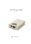
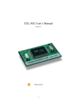
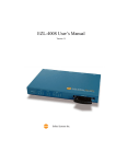
EZL-300W Lite User’s Manual
Version 0.9
Sollae Systems Co., Ltd.
TABLE OF CONTENTS
1.
OVERVIEW····················································································- 5 -
1.1.
Overview ·························································································································- 5 -
1.2.
Components ····················································································································- 5 -
1.3.
Specifications ··················································································································- 6 -
1.4.
Interface Specifications ·································································································- 6 -
1.4.1.
Power ··························································································································- 6 -
1.4.2.
RS232 Dsub Connector ·······························································································- 7 -
1.4.3.
Status LED ··················································································································- 8 -
1.4.4.
Wireless LAN Interface·······························································································- 8 -
2.
INSTALLATION AND TEST OPERATION ····································- 9 -
2.1.
Installation ······················································································································- 9 -
2.1.1.
Checking Communication Environment ····································································- 10 -
2.1.2.
Configuring the Wireless LAN··················································································- 10 -
2.1.3.
Connecting to the Network························································································- 10 -
2.1.4.
Setting Environment Variables ··················································································- 11 -
2.2.
Test Operation·············································································································· - 11 -
2.2.1.
Changing the IP Address of the PC ···········································································- 11 -
2.2.2.
Installing the AP········································································································- 11 -
2.2.3.
Installing ezTCP········································································································- 11 -
2.2.4.
Configuring ezTCP ···································································································- 12 -
2.2.5.
Connecting via the Serial Port of the PC····································································- 13 -
2.2.6.
Communication Test ·································································································- 13 -
3. CONFIGURING WIRELESS LAN, IP ADDRESS, AND
ENVIRONMENT VALUES·································································· - 14 3.1.
Configuring Wireless LAN ·························································································- 14 -
3.1.1.
Items to Check for the Wireless LAN········································································- 14 -
3.1.2.
Setting Wireless LAN Items of the ezTCP·································································- 16 -
-2-
3.2.
Setting the IP Address and Environment Values······················································- 17 -
3.2.1.
ezConfig····················································································································- 18 -
3.2.2.
AT Command············································································································- 22 -
3.2.3.
Setting the IP Address Using the ARP·······································································- 22 -
3.2.4.
Setting IP Address-related Items through the DHCP Server ······································- 23 -
4.
OPERATION MODE ···································································· - 24 -
4.1.
Overview and How To Enter Each Mode··································································- 24 -
4.1.1.
Overview···················································································································- 24 -
4.1.2.
How To Enter Each Mode ·························································································- 24 -
4.2.
Serial Configuration Mode and ISP Mode································································- 26 -
4.2.1.
Serial Configuration Mode ························································································- 26 -
4.2.2.
ISP Mode ··················································································································- 26 -
4.3.
Normal Communication Mode···················································································- 26 -
5.
NORMAL COMMUNICATION MODES ······································· - 28 -
5.1.
T2S (TCP to Serial)······································································································- 28 -
5.2.
ATC (AT Command)····································································································- 30 -
5.3.
COD(Connect On Demand)························································································- 32 -
5.4.
U2S (UDP to Serial) ·····································································································- 34 -
6.
ATC MODE ··················································································- 36 -
6.1.
Overview ·······················································································································- 36 -
6.1.1.
AT command format··································································································- 36 -
6.2.
Basic AT Commands····································································································- 36 -
6.3.
Extended AT commands······························································································- 37 -
6.4.
Online State and Online Command State ·································································- 37 -
6.4.1.
How to switch to online command state from online state ·········································- 38 -
6.4.2.
How to switch to online command state ····································································- 38 -
-3-
6.5.
Example of Configuration by AT Commands ··························································- 38 -
6.6.
Example of Connection ·······························································································- 39 -
6.6.1.
Example of Active Connection ··················································································- 39 -
6.6.2.
Example of Passive Connection·················································································- 39 -
6.7.
Example of Termination······························································································- 39 -
6.7.1.
Example of Active Termination ·················································································- 39 -
6.7.2.
Example of Passive Termination················································································- 40 -
7. TECHNICAL SUPPORT, WARRANTY, AND NOTES ON
OPERATION ······················································································ - 41 7.1.
Technical Support········································································································- 41 -
7.1.1.
Warranty ···················································································································- 41 -
7.1.2.
Refund·······················································································································- 41 -
7.1.3.
Free Repair Services··································································································- 41 -
7.1.4.
Charged Repair Services ···························································································- 41 -
7.1.5.
Notes on Operation····································································································- 42 -
-4-
1. OVERVIEW
1.1.
Overview
With the development of Internet technologies, demands for data communication
through the Internet keep increasing. However, to have data communication through
the Internet, users must use TCP/IP protocol which is the basic communication protocol
of the Internet. In other words, to connect a device to the Internet, the user must
implement TCP/IP protocol. To implement TCP/IP protocol, the user must implement
TCP/IP protocol by themselves, port open TCP/IP, or use an OS. However, these
methods are quite burdensome in terms of time, cost, and technology.
As a family of serial to TCP/IP protocol converters, ezTCP series manufactured by
Sollae Systems provide TCP/IP communication functions (Internet communication
functions) "only through serial port connection." The ezTCP series perform TCP/IP
protocol processing on data received from the serial port, and send the processed data to
the Internet. Similarly, the ezTCP series perform TCP/IP protocol processing on data
received from the Internet and sends the processed data to the serial port.
EZL-300W Lite(it is pronounced as “lait”), which is one of ezTCP products, provides
TCP/IP communication through IEEE802.11b (wireless LAN). In other words, like
other ezTCP products, EZL-300W Lite TCP/IP-processes data received from the serial
port and sends the processed data to the wireless LAN network. And EZL-300W
Lite(hereafter ezTCP) TCP/IP-processes data received from the wireless LAN network
and sends the processed data to the serial port.
ezTCP supports the infrastructure network through the Access Point (AP) and also
provides an "ad-hoc" network function supporting peer to peer communication without
any AP.
As ezTCP provides DHCP as well as TCP/IP/UDP, ezTCP can be applied to cable
networks.
1.2.
Components
z
EZL-300W Lite Main Body
z
3.3V PCMCIA Wireless LAN Card(16bit PC Card) Supporting IEEE802.11b
(option)
z
5V SMPS Adapter (option)
z
RS-232 Cable (option)
-5-
1.3.
Specifications
Power
Input Voltage
5V
Current
320mA typical
Consumption
(It depends on wireless LAN card)
Size
137mm x 78mm x 28mm
Weight
305 g
Interface
Serial
9pin Dsub male
Network
16bit PC card
RS232 level(1200bps ~ 115200bps)
Serial Port
RTS/CTS hardware flow-control
Network
IEEE802.11b wireless LAN(infrastructure/ad-hoc)
Protocols
TCP, UDP, IP, ICMP, ARP, DHCP, WEP
Communicat
T2S
TCP, server mode
COD
TCP, client mode
-ion
Modes
TCP, server/client modes
ATC
(AT command emulation)
U2S
UDP
Operating
0℃ ~ 70℃
Temperature
Utilities
)
1.4.
ezConfig
Configuration utility via LAN
ezSerialConfig
Configuration utility via serial
ezterm
Socket communication utility for test
wflash
Firmware download utility
Download utilities and firmware from http://www.eztcp.com.
Interface Specifications
1.4.1. Power
The user must use the DC5V SMPS power adapter provided by Sollae
Systems. Specifications of a power jack are as shown below.
-6-
1.4.2. RS232 Dsub Connector
A serial port connector is interfaced through the 9pin Dsub male connector. For
specifications of each pin, see the following:
No. Name
Description
Signal Level Direction
Remark
1
NC
2
RXD
Receive Data
RS232
Input
mandatory
3
TXD
Transmit Data
RS232
Output
mandatory
4
DTR
Data Terminal Ready
RS232
Output
Always ON
5
GND
Ground
Ground
-
mandatory
6
DSR
Data Set Ready
RS232
Input
Not used
7
RTS
Request To Send
RS232
Output
optional
8
CTS
Clear To Send
RS232
Input
optional
9
NC
-7-
1.4.3. Status LED
In ezTCP, there are total 5 status LEDs.
Each status LED functions as follows:
Name
Description
Color
LED Status
Description
PWR
Power
Red
Turned on
When the power is on
Blinking
When IP address is
once per
assigned, but no TCP
second
connection established
STS
Status
Yellow
Blinking 4
times every 2
seconds
Turned on
LINK
RXD
TXD
Wireless LAN
Link
Wireless LAN
Reception
Wireless LAN
Transmission
Green
Turned on
Yellow
Turned on
When no IP address was
assigned(DHCP)
During a TCP connection
the wireless LAN LINK is
established
When a packet is received
from the wireless LAN
When a packet is
Green
Turned on
transmitted to the wireless
LAN
1.4.4. Wireless LAN Interface
ezTCP requires PCMCIA wireless LAN card, which should be 3.3V 16 bits PC card
and compatible to PRISM 2.5 or PRISM 3.0 of Intersil.
-8-
2. Installation and Test Operation
2.1.
Installation
Install ezTCP as follows:
Categories
1. Checking
Communication
Environment
Sub-
Context
See
Wireless LAN environment
3.1.1.
categories
Items to
IP address environment
check
Serial port setup values
Application program to use
Setup tool
ezSerialConfig
3.1.2.
Wireless LAN Types
(Infrastructure and ad-hoc)
2. Configuring
the Wireless
LAN
Setup Items
Service Set Identification (SSID)
3.1.1.
Channel
Whether to use WEP
(If used, set key value)
3. Connecting
Confirming
to the Network
Procedure
Checking link LED lightning status
Set by ezConfig
(a configuration utility through a network)
3.2.1.
Setup
Procedure
Using AT command in ATC mode
Using ARP
4. Setting
(To set only the IP address temporarily)
Environment
Variables
Setup Items
6.
3.2.3.
IP address-related items
3.2.
Serial port-related items
3.2.
Communication mode
(To be decided according to the application
program)
5. Field Application
-9-
4.3.
2.1.1. Checking Communication Environment
Before installing ezTCP, the user must check conditions of the network to install the
ezTCP as follows:
z
Wireless LAN network types (infrastructure/ad-hoc)
z
the SSID and the channel of the wireless LAN
z
Whether to use WEP and WEP setup values (the number of bits and key
values)
z
Authentication Protocol for wireless LAN access
z
IP address environment (Local IP, subnet mask, gateway, etc.)
z
Serial port items of the device to connect (baudrate, databit, parity, and stop
bit)
z
)
Protocol of the application program to use (TCP/UDP, server/client, etc.)
For more information about the wireless LAN, see “ 3.1 Configuring the
Wireless LAN."
)
For more information about protocol of the application program to use, see
“4.3 Normal Communication Mode.”
※ It is not applicable to a wireless LAN which use authentication, because ezTCP
doesn’t support authentication protocols for the wireless LAN
2.1.2. Configuring the Wireless LAN
Before using the ezTCP, the user must set wireless LAN-related items. Wireless LANrelated items can be set via ezSerialConfig in a serial configuration mode. Supply
power without the PCMCIA card insertion to enter into the serial configuration
mode. In the serial configuration mode, the user can set not only wireless LAN-related
items but also all setup values of the ezTCP.
)
For more information about the serial configuration mode, see “4. Operation
Modes."
)
For more information about wireless LAN-related items in serial configuration
mode, see “3.1 Configuring the Wireless LAN.”
2.1.3. Connecting to the Network
Insert the PCMCIA card while power is not supplied. Then, connect the device with the
- 10 -
ezTCP using RS232 cable that is compliant with the specification, and supply
power. After power is supplied, the link LED should be turned on. When the link
LED is on, it means that a link has been established between the AP and wireless LAN
device or between the wireless LAN devices to enable communication between them.
2.1.4. Setting Environment Variables
Once a connection to the network has been established, set environment variables variables relating to the IP address, the serial port, and communication mode - using
ezConfig which is an environment variable configuration program.
)
For more information about environment variables, see “ 3.2 Setting IP
Address and Environment Values.”
2.2.
Test Operation
Perform test operation according to the following sequence. A method to perform the
test operation will now be described, assuming that the network is configured as the
infrastructure, the AP and the PC are directly connected via a crossed LAN cable, and
the IP address of the PC is 10.1.0.2.
2.2.1. Changing the IP Address of the PC
Change the IP address of the PC as follows:
IP Address
10.1.0.2
Subnet Mask
255.0.0.0
Gateway IP Address
0.0.0.0
2.2.2. Installing the AP
Connect the AP with the PC through the crossed LAN cable.(When connecting through
a hub, use a one-to-one cable for this connection.) After installing the cable, supply
power to the AP as provided by the AP vendor. After supplying power, check the link
LED indicating a connection between the AP and PC to make sure this connection is
successfully made.
2.2.3. Installing ezTCP
Connect the PC with ezTCP using RS232 cable provided by Sollae Systems, and insert
the PCMCIA card. When power is supplied using the power adapter designed for
- 11 -
ezTCP by Sollae Systems, ezTCP attempts making a connection with the AP that
replies first. Once ezTCP is connected with the AP, the link LED is turned on and then a
communication through the wireless LAN is possible.
※ It is possible that ezTCP connect other AP because SSID is not set. In this case,
you should set SSID to ezTCP via ezSerialConfig
2.2.4. Configuring ezTCP
Use ezConfig (the ezTCP configuration program) and change the configuration
of ezTCP as follows:
Run ezConfig, and click on [PROBE] button on the ezConfig window. Then, the
ezConfig will search for ezTCPs.
Once the ezTCP(s) is(are) found, the MAC address (hardware address) indicated at the
bottom of the ezTCP case will be displayed in the [MAC ADDRESS LIST] window.
Select the corresponding MAC address, and change the [MUX TYPE] into
[T2S(0)]. Then, enter 1470 in the [LOCAL PORT] field and click on [WRITE] button
to save the setup values.
- 12 -
2.2.5. Connecting via the Serial Port of the PC
Connect between the serial port of the PC and the serial port of the ezTCP using the
serial communication cable provided by Sollae Systems.
Then, run a serial
communication program such as Hyper Terminal. Select 19200bps for the serial port, 8
bits for the data bit, 1 bit for the stop bit, and no parity.
2.2.6. Communication Test
Once the preparation for serial communication has been completed, enter the following
in the command prompt of Windows, and establish a TCP connection using Telnet
program.
"telnet 10.1.0.1 1470"
When TCP connection is successfully established, "STS" LED of the ezTCP is turned on.
If "123" data is transmitted to Telnet window after checking that "STS" LED is on, then
"123" is displayed on Hyper Terminal. If "ABC" data is transmitted to Hyper Terminal
window, then "ABC" data is displayed on Telnet window. It means the communication
test is successful.
- 13 -
3. Configuring Wireless LAN, IP Address, and
Environment Values
Configuring Wireless LAN
3.1.
When configuring the wireless LAN, the user must check the network type and security
issues of the network currently being used or to be installed in the future.
3.1.1. Items to Check for the Wireless LAN
z
Network Type (infrastructure/ad-hoc)
The infrastructure is a network connection mode that allows communication between
wireless LAN devices or between the wireless LAN and the wired LAN (Ethernet)
through the Access Point (AP). When a network type is set to infrastructure,
communication with wired LAN via AP is possible, which allows both wired and
wireless Internet communications.
<Infrastructure>
The ad-hoc network is designed to communicate between wireless LANs without any
- 14 -
AP. Since communication is established without any AP, the user cannot access an
external network or the Internet. This is also called a peer-to-peer mode.
<Ad-hoc>
z
Service Set Identifier (SSID)
When configuring a network, the user can configure different networks using different
APs. In this case, the SSID is used to differentiate one network from another. In other
words, when configuring an infrastructure network, the user can make communication
with the AP which he/she wants to communicate with by setting the SSID of the desired
AP in the ezTCP. (See 3.1.2.) For information about SSID of the AP, AP manual or AP
configuration program can be referred to. If the user did not set the SSID, the ezTCP
will be connected with the AP that is first found when power is supplied.
The maximum length of the SSID is 32 bytes, and the user can use ASCII code to set the
SSID.
z
Channel
The channel is communication path in the network that it belongs to. Channel values
are set as the same value with the AP.
z
Wired Equivalent Privacy (WEP)
- 15 -
This is about security of the wireless LAN. The wireless LAN provides similar security
to that of the wired LAN using the WEP. To use the WEP, the user must set the key
value. According to the key value, data is encoded in 64 bits or 128 bits for
communication. If the user did not set the WEP, security-related problems may occur.
z
Authentication Protocols
To avoid illegal access to wireless LAN, there are various authentication protocols.
But ezTCP doesn’t support any authentication protocol. If a wireless LAN network uses
any authentication protocol, you should not install ezTCP to that network.
3.1.2. Setting Wireless LAN Items of the ezTCP
There are two ways to configure wireless LAN-related items - Windows
utility “ezSerialConfig”..
The following table describes each configuration field.
Field
TARGET
SSID
Description
SSID of the Network to Participate
CREATE
SSID of the Network to Newly Create When
SSID
Configuring an Ad-hoc Network
Factoryset
Not set.
Not set.
0) IBSS: Ad-hoc Network
CC TYPE
1) BSS: Infrastructure Network
2) WDS: Reserved (Reserved)
1
3) Pseudo IBSS: Reserved (Reserved)
CHANNEL
Channel number
0
0) WEP is not used.
WEP TYPE
1) 64 bit WEP key
0
2) 128 bit WEP key
KEY ID
Number of the Key to be Used
0
Authentication
For setting EAP-MD5
OFF
- 16 -
z
Setting via ezSerialConfig utility
Operate ezTCP in serial configuration mode to utilize ezSerialConfig. Follow the
sequence as described below.
1. Run ezSerialConfig program in the PC.
2. With no LAN card inserted, connect ezTCP and the PC by a serial cable and apply
power.
3. Select the COM port of the PC to which the cable is connected and press the
[READ] button.
4. Configure the environmental parameters of ezSerialConfig. At this time, you should
configure wireless LAN-related items. (The other items may be configured with
ezConfig program after the wireless LAN is inserted into ezTCP.)
5. Push the [WRITE] button in the ezSerialConfig window.
3.2.
Setting the IP Address and Environment Values
To establish TCP/IP communication, the user must set fields relating to the IP address as
well as fields relating to the serial port (baud-rate, data bit length, parity bit, flow control,
etc.) in the ezTCP.
The user can set the fields relating to IP address and the serial port through the ezConfig
(a configuration utility through the network) or AT command in ATC mode. To set the
fields, the user also may temporarily set the IP address by the ARP method using the
MAC address (hardware address).
Items
Description
LOCAL IP
ADDRESS
SUBNET
Subnet Mask
MASK
IP Address Fields
ezTCP IP Address
GATEWAY
LOCAL PORT
PEER IP
ADDRESS
PEER PORT
- 17 -
Gateway
Listening Port Number in Server
Mode
peer IP Address in Client Mode
Port Number in Client Mode
BAUD RATE
Baud Rate (bps)
DATA BITS
Data Bit Length
PARITY
Parity
FLOW CTRL
Flow Control
MUX TYPE
Communication Mode
Connection/
WATER
Minimum Number of Bytes to
Connection
MARK
Attempt Connection/Transmission
Termination Event
TIMEOUT
Connection Time Out
Using Configuration
EZCFG
ezConfig Function enable/disable
Method
ARP
ARP function eanble/disable
Floating IP
DHCP
Telnet Password
PASSWORD
Serial Port
Communication
Mode
DHCP(Dynamic Host Configuration
Protocol)
Password when Performing Remote
Login through Telnet
3.2.1. ezConfig
The basic environment information of ezTCP can be configured through DHCP, ARP,
and ezConfig. This section takes an example of using ezConfig, which is a configuration
program via wired/wireless LAN. For the other configuration modes, see the following
sections. ezConfig can run on Microsoft Windows platform but may not operate on
some of the existing operating systems. The screen below shows the initial screen of
ezConfig:
ezConfig broadcast UDP data to communicate ezTCPs, so it can be used in local
network(If there is a gateway between ezTCP and PC, then ezConfig doesn’t work.)
- 18 -
Each button on ezConfig functions as follows:
This button is used to search for all of the network-attached ezTCPs. The
search results will be displayed on the MAC ADDRESS LIST box and you can select an
item using a mouse or cursor as required. The value displayed on the box indicates the
MAC ADDRESS of each ezTCP. The selected setup value of ezTCP will be displayed
on the right side.
You can see only the ezTCP configuration values if you press this button after
entering the 6-digit hexadecimal number printed on the ezTCP main body in the MAC
ADDRESS box. It is useful when there are too many ezTCPs attached to the network to
search for one from the LIST box.
This button is used to save the changed value in ezTCP after modifying the
configuration. Make sure not to press this button during operating ezTCP since ezTCP
will automatically be reset right after its environment setup value is saved. Otherwise, it
may cause malfunction.
This button is used to close ezConfig. You can also close it by pressing ESC
key on the keyboard.
ezTCP provides User Authentication function to prevent an unwanted person
from modifying the configuration. The authentication process is performed through the
password string verification. When entering or changing the password strings, you can
use this button. Changing the ezTCP configuration details if a password has been
entered requires the proper password to be entered in the PASSWORD field.
This button is used to read a dynamic variable value during operating ezTCP.
Pressing this button will display a new window, where the time-elapsed after the power
- 19 -
is on, the current IP address, and the data throughput of the serial port are indicated.
Double-clicking each item on the MAC ADDRESS LIST will carry out the same
function.
ezConfig can be used to change the IP address related items, the serial port setup value,
the serial port operation mode, and how to setup ezTCP. This section describes these
functions briefly. For more information, see the following sections.
The following example shows how to read and change ezTCP's basic functions. Try
changing ezTCP setup value according to the following sequence:
- When the ezTCP power is turned on and the LAN cable is connected correctly,
pressing [PROBE] or [READ] button will display the following window:
- If a network-attached ezTCP is detected, the following message will be displayed. If a
message pops up indicating that there is no response from ezTCP, check that the power
is turned on and the cable is connected correctly, then try pressing [PROBE] or [READ]
button.
- If more than one ezTCP are detected, ezTCP's MAC ADDRESS will be displayed in
the [MAC ADDRESS LIST] box on ezConfig. Check if the MAC ADDRESS displayed
in the [MAC ADDRESS LIST] window corresponds to that printed on ezTCP main
body. The following screen shows this process:
- 20 -
- Select T2S (0) in the [MUX TYPE] field on ezConfig. Setup [LOCAL IP ADDRESS],
[LOCAL PORT], and the serial port settings according to a test environment as required.
When the setup is completed, pressing [WRITE] will save the changed values in ezTCP.
If an error message pops up during storing the configuration, check that ezTCP is
connected correctly, and then try again.
- In Windows' MS-DOS prompt window, check the IP address is set correctly by giving
the PING command. If the ezTCP IP address is set correctly, the PING results will be
displayed as follows. If a message, "Request timed out", is displayed, check that IP
address setup value again.
C:\>ping a.b.c.d
Pinging a.b.c.d with 32 bytes of data:
Reply from a.b.c.d: bytes=32 time=1ms TTL=64
Reply from a.b.c.d: bytes=32 time=1ms TTL=64
Reply from a.b.c.d: bytes=32 time=1ms TTL=64
Reply from a.b.c.d: bytes=32 time=1ms TTL=64
- 21 -
3.2.2. AT Command
In ATC mode, the user can set environment variables through the serial port using AT
command.
)
See “6. ATC MODE".
3.2.3. Setting the IP Address Using the ARP
On Windows and UNIX(Linux) platform, the command 'arp' enables a user to change
the contents of arp cache table from the host computer. After changing the contents of
the arp cache table, attempting a Telnet connection or a ping test will change the
ezTCP's IP address. IP address changed by the arp command will not be stored in
EEPROM. Therefore, the user should change the IP-related items by giving "env if"
command through telnet access. ezTCP allows the user to change the IP address only
one time after the power is turned on. For that reason, the user should reset ezTCP
when changing the IP address.
The example listed below shows how to change the arp cache table on Windows' MSDOS prompt window and Linux. If ezTCP's Ethernet address is 00:30:f9:00:00:01 and
the IP address to use is a.b.c.d., the user can change the IP address as follows:
z
Windows
C:\>arp -s a.b.c.d 00-30-f9-00-00-01
☜ Change the table.
C:\>arp -a
☜ Check changes.
Interface: xxx.xxx.xxx.xxx on Interface xxxxxxxx
Internet Address
a.b.c.d
Physical Address
Type
00-30-f9-00-00-01 static
☜ Access the ezTCP.
C:\>telnet a.b.c.d
C:\>
□ Linux
- 22 -
rtos:~>arp -s a.b.c.d 00:30:f9:00:00:01
☜ Check changes.
rtos:~>arp
Address
a.b.c.d
☜ Change the table.
HWtype HWaddress
ether
00:30:f9:00:00:01
FLags Mask Iface
CM
eth0
☜ pinging to ezTCP
rtos:~>ping a.b.c.d
3.2.4. Setting IP Address-related Items through the DHCP Server
Under environment with a network operating a DHCP server, DHCP protocol allows the
user to automatically set the IP address, subnet mask, gateway, and name server of
ezTCP. Using DHCP automatic setup function requires the user to check [DHCP] item
on ezConfig. Note that the user may have to check [ARP] item according to the type of
DHCP servers.
※ When setting the IP address through the DHCP server, the IP
address is dynamically allocated. Therefore, the user cannot use T2S
and U2S mode.
- 23 -
4. OPERATION MODE
4.1.
Overview and How To Enter Each Mode
4.1.1. Overview
There are 3 modes (normal mode, serial configuration mode, ISP mode) in ezTCP.
ezTCP does normal operation in the normal mode, and it configures environmental
variables(especially wireless LAN related item), and it perform firmware upgrading in
ISP mode.
The operation modes of ezTCP are normal communication mode, serial configuration
mode and ISP mode. Major differences among the modes are as follows.
4.1.2. How To Enter Each Mode
z
Normal mode
ezTCP operates in the normal mode if a PCMCIA card is inserted. ezTCP attempt to
connect a link to wireless LAN at first. And LINK LED is on after connection.
z
Serial configuration mode
ezTCP operates in the serial configuration mode if it is turned on without LAN card
insertion. In serial configuration mode, all environmental variables can be set including
wireless LAN related items.
z
ISP mode
After connecting PC and ezTCP via serial cable, run serial terminal program(i.e. Tera
Term Pro) which can transmit binary file with 115200bps baudrate. As soon as it is
turned on, if you input <CR>(0x0d), you can see a “000” message. If you should input
“flash”, then you can enter ISP mode.
Following is the message when ezTCP enters to ISP mode.
000
100 AVR/64 BOOTLDR 10 SOLLAE SYSTEMS 203 vender: 0x1F, device code: 0x35
Following is an explanation of each mode.
Op. Mode
Normal Comm
Mode
Description
Normal operation
(TCP/IP protocol conversion)
- 24 -
Related Utility
LAN Card
ezConfig
Inserted
Serial
Configuration
Mode
ISP Mode
Sets up parameters including wireless
LAN items through the serial port.
Upgrades the ezTCP firmware through
the serial port.
The Following describes the booting sequence of ezTCP.
- 25 -
ezSerialConfig
Not inserted
wflash
Not inserted
4.2.
Serial Configuration Mode and ISP Mode
4.2.1. Serial Configuration Mode
You can set all items including wireless related items and IP related items via
ezSerialConfig in the serial Configuration mode.
4.2.2. ISP Mode
In ISP mode, you can download a firmware which is supplied from Sollae Systems.
Buadrate
115200 bps
parity
No parity
Data bit
8 bits
Stop bit
1 bit
The following describes the firmware download method.
)
If you use wflash which is supplied by Sollae Systems, you can download
firmware more easily.
4.3.
Normal Communication Mode
This is the normal communication mode of ezTCP as designed for its purpose.
When you apply power to an ezTCP product with the LAN card inserted, It will
initiates normal communication mode.
In normal communication mode are available four communication modes, T2S, ATC,
COD and U2S, as shown in the table below.
- 26 -
Comm.
Mode
Protocol
Connection
S/W
Type
Modification
Parameter change
through the serial
Topology
port
T2S
TCP
Passive
Not needed
No
1:1
ATC
TCP
Active/Passive
Needed
Possible
1:1
COD
TCP
Active
Not needed
No
1:1
U2S
UDP
No connection
Not needed
No
N:M
TCP is a protocol that requires a connection process. Connection always takes place a
one-to-one basis. A host waiting for connection (passive connection) is called a server,
and one attempting to make a connection (active connection) is called a client.
On the other hand, UDP communicates by the block without the process of connection,
and thus allows multiple hosts to communicate simultaneously.
)
For detailed operation modes, refer to the next chapter.
- 27 -
5. NORMAL COMMUNICATION MODES
5.1.
T2S (TCP to Serial)
In T2S mode, the ezTCP functions as a server.
When a TCP connection comes from a remote host to the predefined local port,
the ezTCP accepts a TCP connection. When the ezTCP accepts TCP connection,
then the TCP connection is established. After connection is established, TCP/IP
processing is performed on the data coming to the serial port, which is then
transmitted to the remote host. And the TCP/IP data coming from the remote host
is TCP/IP-processed and transmitted to the serial port to establish data
communication. (Data coming to the serial port before TCP connection is
established will be ignored.)
In T2S mode, the ezTCP functions as a server. Therefore, T2S mode cannot
be used in a dynamic IP environment (DHCP)
- 28 -
Set the following for T2S mode:
IP Addresses
Serial Port
Mode
Connection
Disconnection
Field
Description
LOCAL IP ADDRESS
Local IP address of ezTCP
SUBNET MASK
Subnet mask
GATEWAY
Gateway IP address
LOCAL PORT
Local port number to listen
PEER IP ADDRESS
-
PEER PORT
-
BAUD RATE
Speed of serial port(bps)
DATA BITS
Data length
PARITY
Parity
FLOW CTRL
Flow control
MUX TYPE
T2S(0)
WATER MARK
Connection is terminated if there’s no
TIMEOUT
transmission data during [TIMEOUT]
Configuration
EZCFG
ezConfig function enable/disable
Method
ARP
ARP function enable/disable
Dynamic IP
DHCP
-
- 29 -
5.2.
ATC (AT Command)
In ATC mode, the user can control the ezTCP in a similar way to controlling the modem
using AT command. In ATC mode, only a TCP connection is possible and both the
server and the client can be configured.
In ATC mode, the AT command allows the user to set environment variables including
the
IP
address
and
control
TCP
- 30 -
connection
and
disconnection.
Set the following for ATC mode:
IP Addresses
Serial Port
Mode
Connection
Disconnection
)
Field
Description
LOCAL IP ADDRESS
Local IP address of ezTCP
SUBNET MASK
Subnet mask
GATEWAY
Gateway IP address
LOCAL PORT
Local port number to listen
PEER IP ADDRESS
IP address of host to connect
PEER PORT
Port number of host to connect
BAUD RATE
Speed of serial port(bps)
DATA BITS
Data length
PARITY
Parity
FLOW CTRL
Flow control
MUX TYPE
ATC(1)
WATER MARK
Connection is terminated if there’s no
TIMEOUT
transmission data during [TIMEOUT]
Configuration
EZCFG
ezConfig function enable/disable
Method
ARP
ARP function enable/disable
Dynamic IP
DHCP
DHCP function enable/disable
Confer next chapter to get more information about AT commands.
- 31 -
5.3.
COD(Connect On Demand)
In COD mode, the ezTCP functions as a client.
When data of the pre-specified size [WATER MARK] comes to the serial port,
the ezTCP attempts a TCP connection to the TCP port [PEER PORT] of the
preset host IP [PEER IP ADDRESS]. If the remote host accepts the TCP
connection, TCP connection will be established. Data coming to the serial port
after connection establishment is TCP/IP-processed and transmitted to the remote
host. And, data coming from the remote host is TCP/IP-processed and
transmitted to the serial port for data communication.
- 32 -
Set the following for COD mode:
IP Addresses
Serial Port
Mode
Field
Description
LOCAL IP ADDRESS
Local IP address of ezTCP
SUBNET MASK
Subnet mask
GATEWAY
Gateway IP address
LOCAL PORT
-
PEER IP ADDRESS
IP address of host to connect
PEER PORT
Port number of host to connect
BAUD RATE
Speed of serial port(bps)
DATA BITS
Data length
PARITY
Parity
FLOW CTRL
Flow control
MUX TYPE
COD(2)
the number of bytes.
Connection
ezTCP attempts a connection when it
WATER MARK
receive a mount of [WATER MARK]
Disconnection
from its serial port.
Connection is terminated if there’s no
TIMEOUT
transmission data during [TIMEOUT]
Configuration
EZCFG
ezConfig function enable/disable
Method
ARP
ARP function enable/disable
Dynamic IP
DHCP
DHCP function enable/disable
- 33 -
5.4.
U2S (UDP to Serial)
U2S mode allows for UDP communication.
In UDP mode, data are transmitted in blocks, which requires dividing data
coming to the serial port into blocks before transmitting data. A procedure for
dividing data into blocks is as follows:
If data of pre-specified bytes [WATER MARK] comes to the serial port of the
ezTCP or if a specified period of time [TIMEOUT] elapses after first data reception,
all data received for the same period is recognized as one block which is then
transmitted to the UDP. The [TIMEOUT] unit is 10ms. If [TIMEOUT] is set to 2,
the time period is between 20ms and 30ms.
Since UDP communication does not require a connection procedure, the user can
establish N-to-M communication via multicast and broadcast.
In U2S mode, ezTCP doesn’t support DHCP.
- 34 -
U2S 일 때 설정해야 할 사항은 다음과 같습니다.
IP Addresses
Serial Port
Mode
Transmission
Unit
Field
Description
LOCAL IP ADDRESS
Local IP address of ezTCP
SUBNET MASK
Subnet mask
GATEWAY
Gateway IP address
LOCAL PORT
Port number to receive UDP data
PEER IP ADDRESS
IP address of host to send UDP data
PEER PORT
Port number of host to send UDP data
BAUD RATE
Speed of serial port(bps)
DATA BITS
Data length
PARITY
Parity
FLOW CTRL
Flow control
MUX TYPE
U2S(3)
WATER MARK
Byte size starting to send
Receiving interval to send as a block
TIMEOUT
(unit: 10msec)
Configuration
EZCFG
ezConfig function enable/disable
Method
ARP
ARP function enable/disable
Dynamic IP
DHCP
-
- 35 -
6. ATC MODE
6.1.
Overview
In ATC mode, it is possible to set up and control ezTCP by use of AT commands,
which are modem commands. For instance, you can set the remote IP to connect by
AT+PRIP command and make connection by ATD command. Thus, communication with
multiple hosts in turn is possible. Also you can make passive connection by ATA
command.
6.1.1. AT command format
AT commands start with “AT” and end with <CR>.
The format of AT commands is as follows.
AT
Command
<CR>(0x0d)
The response code from ezTCP to an AT command is as follows.
Response Message
<CR>(0x0d)
<LF>(0x0a)
Response Message
6.2.
ATV1 (Initial setup)
ATV0
Description
OK
0
Command OK
ERROR
4
Command error
CONNECT
1
TCP connection established
NO CARRIER
3
TCP connection terminated
SET VALUE
SET VALUE
When a set value is queried
(Ex: AT+PRIP?)
Basic AT Commands
Command
Function
A
passive connection
D
active connection
Description
Listening connection
(connection from host to ezTCP)
Starting to connect to host
- 36 -
6.3.
6.4.
Enable/disable echo of AT command
E
echo
H
off-hook
Terminating Connection
I
Inquery
Showing ezTCP’s Information
O
Online
Toggle to on-line sate
V
response code
Z
reset
(ATE1-enable, ATE0-diable)
The type of response code
(numeric-V0, verbose-V1)
Initializing ezTCP
Extended AT commands
Command
Function
Description
+PLIP
local IP address
+PSM
subnet mask
+PGIP
default router
+PLP
listening TCP port
+PTO
timeout
+PRIP
Remote machine IP address
+PRP
Remote machine TCP port
+PWP
Write configuration
+PRC
Enable/disable ezConfig
ON: 1, OFF: 0
+PARP
Enable/disable ARP
ON: 1, OFF: 0
+PDC
DHCP
ON: 1, OFF: 0
Saving configuration values
to EEPROM
Online State and Online Command State
If connection has not been established in ATC mode, the system is in online command
mode and permits the use of AT commands.
Once connection has been established, the system is in online state and does not
permit the use of AT commands. In order to use AT commands while TCP connection is
established, it is necessary to switch to online command state and then use AT
commands.
- 37 -
Online command
While TCP connection is not established, AT commands can be
state
used.
While TCP connection is established, all data are converted to
Online state
TCP/IP.
6.4.1. How to switch to online command state from online state
In order to switch from online state to online command state, it is necessary to send a
‘+++’ message in proper format within specified time. The ‘+++’ message will be sent to
the peer host.
The time interval between the last data transmission
and inputting the first ‘+’
The time between ‘+’s
500ms or up
0~500ms
The interval which is no data transmission after the
last ‘+’
500ms or up
6.4.2. How to switch to online command state
In case the system has been switched from online state to online command state while
TCP connection is established, it can be switched back to online state by ATO command.
6.5.
Example of Configuration by AT Commands
Transmission Data
AT+PLIP=192.168.1.200<CR>
Description
▶ Set local IP address
◀ OK<CR><LF>
AT+PGIP=192.168.1.254<CR>
Command OK
▶ Set gateway IP address
◀ OK<CR><LF>
AT+PSM=255.255.255.0<CR>
Command OK
▶ Set subnet mask
◀ OK<CR><LF>
AT+PLP=1470<CR>
Command OK
▶ Set local port
◀ OK<CR><LF>
AT+PTO=10<CR>
Command OK
▶ Set TIME OUT
◀ OK<CR><LF>
AT+PWP<CR>
Command OK
▶ Save configuration data to the EEPROM
◀ OK<CR><LF>
Command OK
- 38 -
◀ NO CARRIER<CR><LF>
6.6.
After system resets
Example of Connection
6.6.1. Example of Active Connection
Transmission Data
AT+PRIP=192.168.1.201<CR>
Description
▶ Set remote IP address to connect
◀ OK<CR><LF>
AT+PRP=1470<CR>
Command OK
▶ Set remote port number to connect
◀ OK<CR><LF>
Command OK
▶ Connect to the remote host
ATDT<CR>
Attempting a connection
◀ CONNECT<CR><LF>
Connection established
TCP/IP data transmission
6.6.2. Example of Passive Connection
데이터
AT+PLP=1470<CR>
◀ OK<CR><LF>
설명
▶ Set local port
Command OK
▶ Listen connection
ATA<CR>
Listening connection from remote host
Connection from remote host
◀ CONNECT<CR><LF>
Connection established
TCP/IP data transmission
6.7.
Example of Termination
6.7.1. Example of Active Termination
The following is the sequence to terminate connection initiated by ezTCP.
Data
Description
Data exchange (TCP connection established)
- 39 -
[guard time]+++[guard time]
switching to online command state from
▶
online state.
switching to online command state
◀ <CR><LF>OK<CR><LF>
completed
▶ TCP termination command
ATH
◀ OK<CR><LF>
6.7.2.
TCP connection terminated
Example of Passive Termination
In case an external host attempts to terminate a connection;
Data
Description
Data exchange (TCP connection established)
In case an external host attempts to terminate connection
◀ NO CARRIER<CR><LF>
TCP connection terminated
- 40 -
7. Technical Support, Warranty, and Notes on
Operation
7.1.
Technical Support
If you have any question regarding operation of the product, visit Customer Support
FAQ corner and the message board on Sollae Systems' web site or send us an email at
the following address:
Website Address for Customer Support:
http://www.sollae.co.kr/Support/index.html
Email Address:
7.1.1. Warranty
7.1.2. Refund
Upon the customer's request to refund the product within two weeks after
purchase, Sollae Systems will refund the product.
7.1.3. Free Repair Services
For product failures occurring within one year after purchase, Sollae Systems
provides free repair services or exchange the product. However, if the product
failure is due to user's fault, repair service fees will be charged or the product will
be replaced at user's expense.
7.1.4. Charged Repair Services
For product failures occurring after the warranty period (one year) or resulting
from user's fault, repair service fees will be charged and the product will be
replaced at user's expense.
- 41 -
7.1.5. Notes on Operation
z
Sollae Systems is not responsible for product failures occurring due to user's
alternation of the product.
z
Specifications of the product are subject to change without prior notice for
performance improvement.
z
Sollae Systems does not guarantee successful operation of the product if the
product was used under conditions deviating from the product specifications.
z
Reverse engineering of firmware and applications provided by Sollae Systems
is prohibited.
z
Use of firmware and applications provided by Sollae Systems for purposes
other than those for which they were designed is prohibited.
z
Do not use the product in an extremely cold or hot place or in a place where
vibration is severe.
z
Do not use the product in an environment in which humidity is high or a lot of
oil exists.
z
Do not use the product where there is caustic or combustible gas.
z
Sollae Systems does not guarantee normal operation of the product under the
conditions a lot of noise exists.
z
Do not use the product for a purpose that requires exceptional quality and
reliability relating to user's injuries or accidents - aerospace, aviation, health care,
nuclear power, transportation, and safety purposes.
z
Sollae Systems is not responsible for any accident or damage occurring while
using the product.
- 42 -