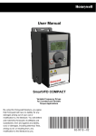
1
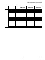
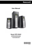
SmartVFD Disconnect Panel
Assemblies
INSTALLATION INSTRUCTIONS
APPLICATION
Disconnect Only
The SmartVFD Disconnect Panel Assemblies channel
electrical power either through or around the variable
frequency drive (VFD).
INSTALLATION
When Installing This Product
1.
2.
3.
4.
5.
Read these instructions carefully. Failure to follow them
could damage the product or cause a hazardous condition.
Check the ratings given in the instructions, Honeywell
SmartVFD manual and on the product to make sure the
product is suitable for your application.
Verify disconnect panel model is correct; no damage
has been incurred; no screws, connections, terminations are loose.
Installer must be a trained, experienced service Technician, with VFD operation experience.
After installation is complete, check out product operation as provided in these instructions.
WARNING
Can Cause Serious Injury or Death.
1. Installation requires work with voltages that may
cause serious injury or death.
2. This instruction manual is intended as a guide
only. End user is responsible for proper
application of this assembly, insuring proper
conformance, directives, intended use and
maintaining all safety practices as described in
Honeywell SmartVFD manual, local codes, local
safety authorities.
3. Disconnect power supply before installation,
and before any servicing.
CAUTION
Equipment Damage Hazard.
Can short equipment circuitry.
Disconnect power supply before installation.
Location and Mounting
Locate the device in a clean, dry, well-ventilated area with an
ambient temperature below 104°F (40°C).
Refer to SmartVFD manual Installation chapter for free air
space requirements above and to the sides of SmartVFD’s.
Ensure proper branch/short circuit protection is provided.
WIRING
IMPORTANT
All wiring must agree with applicable codes, ordinances and regulations.
Variable frequency drive can store energy. Refer to
VFD manual for safe work practices and appropriate
wait times before servicing after equipment power
has been de-energized.
All safety, warning and caution information located in
Honeywell SmartVFD manual must be read, understood and followed.
Before proceeding, make sure proper branch/short
circuit protection has been provided (see SmartVFD
manual).
1.
Ensure that disconnect panel voltage corresponds with
that of the power supply.
2. To access the disconnect panel wiring compartment:
a. Ensure the main disconnect handle is in the OFF
position.
b. Open the cover.
c. Test for power.
3. Refer to SmartVFD user manual “Power Cabling” and
“Control Unit” for proper power and control wire sizing
information.
4. Terminate input three phase power wiring to line side of
main fused disconnect. Refer to disconnect panel schematic.
5. Terminate three phase motor wiring to motor terminals
“T1”, “T2”, “T3”. Refer to disconnect panel schematic.
6. Terminate all VFD control wiring to the proper terminals
on VFD. Refer to disconnect panel schematic.
Refer to schematic for typical wiring.
IMPORTANT
Use only copper wire with 167°F (75°C) minimum.
62-0439-01
SMARTVFD DISCONNECT PANEL ASSEMBLIES
OPERATION
1.
2.
3.
4.
5.
6.
7.
Before applying power verify main input disconnect
handle is in the “OFF” position.
1. Apply input power, check three phase voltage on line
side of main disconnect switch.
2. Press “Loc/Rem” button and program correct parameters for local (keypad) control. See SmartVFD manuals.
Check motor rotation.
3. If motor is rotating backwards, shut down power, lock
out power source, wait until VFD stored energy has dissipated, switch incoming motor wires on the “T1” and
“T2” terminals in the disconnect panel, or motor wires
“T1” and “T2” in the motor junction box. Re-energize
power and check rotation again.
Make sure disconnect panel and motor are properly
grounded.
Make sure all connection points are tight; including all
disconnect panel connection points.
Make sure all safeties (customer option) are connected
and in working order.
Double check correct voltage is being applied and
power and motor wiring are terminated in the correct
place.
Verify motor FLA does not exceed VFD output amp rating.
Verify building automation system is ready for start,
stop, speed command; all wires are terminated in the
correct location.
Make sure all personnel, debris, etc are clear.
62-0439—01
2
SMARTVFD DISCONNECT PANEL ASSEMBLIES
U1
V1
3
SMART VFD
U2
V2
3
W2
RO1/1 N.C.
RO1/2 CM
RO1/3 N.O.
RO2/1 N.C.
RO2/2 CM
RO2/3 N.O.
RO3/1 CM
RO3/2 N.O.
1
1 ALL PANELS SHIPPED WITH VFD DEFAULT PROGRAMMING
PARAMETERS. SET DIP SWITCHES AS NEEDED.
2 TS1, ENCLOSURE FAN1 STANDARD ON ALL NEMA 3R PANELS.
ENCLOSURE FAN2 ON 30HP, 40HP, AND 100HP AT 480V.
HEATER IS OPTIONAL ON ALL NEMA 3R PANELS. TRANSFORMER
ONLY REQUIRED ON 3R MODELS.
3 DISCONNECT PANEL HAS FUSED MAIN DISCONNECT.
DRIVE ONLY PANEL HAS WIRE TERMINALS. ON DRIVE
ONLY PANEL, CUSTOMER IS RESPONSIBLE FOR BRANCH
CIRCUIT AND SHORT CIRCUIT PROTECTION.
ALL WIRING: USE COPPER WIRE ONLY SUITABLE FOR MIN. 75 DEG. C, FIELD WIRING, NEC CLASS 1.
FIELD WIRE
MOTOR AND FEEDER WIRE SIZE MUST BE IN ACCORDANCE WITH NEC.
WIRE INSIDE C/PNL
OPTION
ON
CURRENT
CURRENT
2
A01
DIP SWITCHES
RS485
AI1
AI2
OFF
VOLTAGE
VOLTAGE
VOLTAGE
LOCATED BEHIND COVER,
RIGHT SIDE OF KEYPAD
CURRENT
2
2
M34226
62-0439—01
3
W1
GND
GND
RELAY OUTPUT 3
21 22 23 24 25 26 32 33
RELAY OUTPUT 2
1 2 3 4 5 6 7 8 9 10 11 12 13 14 15 16 17 18 19 30 A B
RELAY OUTPUT 1
+10VREF: REFERANCE OUTPUT
AI1+: AI, VOLTAGE OR CURRENT
GND/AI1-: AI COMMON
AI2+: AI, VOLTAGE OR CURRENT
GND/AI2-: AI COMMON
24V OUT: 24V AUXILLARY VOLTAGE
GND: I/O GROUND
DIN1: DIGITAL INPUT 1
DIN2: DIGITAL INPUT 2
DIN3: DIGITAL INPUT 3
CM: COMMON FOR DI1 - DI3
24V OUT: 24V AUXILLARY VOLTAGE
GND: I/O GROUND
DIN4: DIGITAL INPUT 4
DIN5: DIGITAL INPUT 5
DIN6: DIGITAL INPUT 6
CM: COMMON FOR DI4 - DI6
AO+: ANALOG SIGNAL +OUT
AO-/GND: ANALOG OUTPUT COMMON
+24VIN: 24V AUXILLARY INPUT VOLTAGE
RS485: NEGATIVE
RS485: POSITIVE
Fig. 1. Fused Disconnect Wiring Diagram.
SMARTVFD DISCONNECT PANEL ASSEMBLIES
Table 1. SmartVFD Fused Disconnect.
Voltage
460
208
62-0439—01
HP
AMPS
Frame
NEMA1
NEMA12
NEMA3R
NEMA1 Fused
Disconnect
NEMA12 Fused
Disconnect
NEMA3R Fused
Disconnect
1.5 HP
3.4A
4
HVFDSB3C0015G110
HVFDSB3C0015G210
HVFDSB3C0015G310
2 HP
4.8A
4
HVFDSB3C0020G110
HVFDSB3C0020G210
HVFDSB3C0020G310
3 HP
5.6A
4
HVFDSB3C0030G110
HVFDSB3C0030G210
HVFDSB3C0030G310
4 HP
8A
4
HVFDSB3C0040G110
HVFDSB3C0040G210
HVFDSB3C0040G310
5 HP
9.6A
4
HVFDSB3C0050G110
HVFDSB3C0050G210
HVFDSB3C0050G310
7.5 HP
12A
4
HVFDSB3C0075G110
HVFDSB3C0075G210
HVFDSB3C0075G310
10 HP
16A
5
HVFDSB3C0100G110
HVFDSB3C0100G210
HVFDSB3C0100G310
15 HP
23A
5
HVFDSB3C0150G110
HVFDSB3C0150G210
HVFDSB3C0150G310
20 HP
31A
5
HVFDSB3C0200G110
HVFDSB3C0200G210
HVFDSB3C0200G310
25 HP
38A
6
HVFDSB3C0250G110
HVFDSB3C0250G210
HVFDSB3C0250G310
30 HP
46A
6
HVFDSB3C0300G110
HVFDSB3C0300G210
HVFDSB3C0300G310
40 HP
61A
6
HVFDSB3C0400G110
HVFDSB3C0400G210
HVFDSB3C0400G310
50 HP
72A
7
HVFDSB3C0500G110
HVFDSB3C0500G210
HVFDSB3C0500G310
60 HP
87A
7
HVFDSB3C0600G110
HVFDSB3C0600G210
HVFDSB3C0600G310
75 HP
105A
7
HVFDSB3C0750G110
HVFDSB3C0750G210
HVFDSB3C0750G310
100 HP
140 A
8
HVFDSB3C1000G110
HVFDSB3C1000G210
HVFDSB3C1000G310
120 HP
170 A
8
HVFDSB3C1250G110
HVFDSB3C1250G210
HVFDSB3C1250G310
150 HP
205 A
8
HVFDSB3C1500G110
HVFDSB3C1500G210
HVFDSB3C1500G310
0.75 HP
3.7A
4
HVFDSB3A0007G110
HVFDSB3A0007G210
HVFDSB3A0007G310
1 HP
4.8A
4
HVFDSB3A0010G110
HVFDSB3A0010G210
HVFDSB3A0010G310
1.5 HP
6.6A
4
HVFDSB3A0015G110
HVFDSB3A0015G210
HVFDSB3A0015G310
2 HP
8A
4
HVFDSB3A0020G110
HVFDSB3A0020G210
HVFDSB3A0020G310
3 HP
11A
4
HVFDSB3A0030G110
HVFDSB3A0030G210
HVFDSB3A0030G310
5 HP
18A
5
HVFDSB3A0050G110
HVFDSB3A0050G210
HVFDSB3A0050G310
7.5 HP
24A
5
HVFDSB3A0075G110
HVFDSB3A0075G210
HVFDSB3A0075G310
10 HP
31A
5
HVFDSB3A0100G110
HVFDSB3A0100G210
HVFDSB3A0100G310
15 HP
48A
6
HVFDSB3A0150G110
HVFDSB3A0150G210
HVFDSB3A0150G310
20 HP
62A
6
HVFDSB3A0200G110
HVFDSB3A0200G210
HVFDSB3A0200G310
25 HP
75A
6
HVFDSB3A0250G110
HVFDSB3A0250G210
HVFDSB3A0250G310
30 HP
88A
7
HVFDSB3A0300G110
HVFDSB3A0300G210
HVFDSB3A0300G310
40 HP
105A
7
HVFDSB3A0400G110
HVFDSB3A0400G210
HVFDSB3A0400G310
50 HP
140 A
8
HVFDSB3A0500G110
HVFDSB3A0500G210
HVFDSB3A0500G310
60 HP
170 A
8
HVFDSB3A0600G110
HVFDSB3A0600G210
HVFDSB3A0600G310
75 HP
205 A
8
HVFDSB3A0750G110
HVFDSB3A0750G210
HVFDSB3A0750G310
4
SMARTVFD DISCONNECT PANEL ASSEMBLIES
Table 1. SmartVFD Fused Disconnect. (Continued)
Voltage
230
HP
AMPS
Frame
NEMA1
NEMA12
NEMA3R
NEMA1 Fused
Disconnect
NEMA12 Fused
Disconnect
NEMA3R Fused
Disconnect
0.75 HP
3.7A
4
HVFDSB3A0007G110
HVFDSB3A0007G210
HVFDSB3A0007G310
1 HP
4.8A
4
HVFDSB3A0010G110
HVFDSB3A0010G210
HVFDSB3A0010G310
1.5 HP
6.6A
4
HVFDSB3A0015G110
HVFDSB3A0015G210
HVFDSB3A0015G310
2 HP
8A
4
HVFDSB3A0020G110
HVFDSB3A0020G210
HVFDSB3A0020G310
3 HP
11A
4
HVFDSB3A0030G110
HVFDSB3A0030G210
HVFDSB3A0030G310
5 HP
18A
5
HVFDSB3A0050G110
HVFDSB3A0050G210
HVFDSB3A0050G310
7.5 HP
24A
5
HVFDSB3A0075G110
HVFDSB3A0075G210
HVFDSB3A0075G310
10 HP
31A
5
HVFDSB3A0100G110
HVFDSB3A0100G210
HVFDSB3A0100G310
15 HP
48A
6
HVFDSB3A0150G110
HVFDSB3A0150G210
HVFDSB3A0150G310
20 HP
62A
6
HVFDSB3A0200G110
HVFDSB3A0200G210
HVFDSB3A0200G310
25 HP
75A
6
HVFDSB3A0250G110
HVFDSB3A0250G210
HVFDSB3A0250G310
30 HP
88A
7
HVFDSB3A0300G110
HVFDSB3A0300G210
HVFDSB3A0300G310
40 HP
105A
7
HVFDSB3A0400G110
HVFDSB3A0400G210
HVFDSB3A0400G310
50 HP
140 A
8
HVFDSB3A0500G110
HVFDSB3A0500G210
HVFDSB3A0500G310
60 HP
170 A
8
HVFDSB3A0600G110
HVFDSB3A0600G210
HVFDSB3A0600G310
75 HP
205 A
8
HVFDSB3A0750G110
HVFDSB3A0750G210
HVFDSB3A0750G310
5
62-0439—01
SMARTVFD DISCONNECT PANEL ASSEMBLIES
62-0439—01
6
SMARTVFD DISCONNECT PANEL ASSEMBLIES
7
62-0439—01
SMARTVFD DISCONNECT PANEL ASSEMBLIES
By using this Honeywell literature, you agree that Honeywell will have no liability for any damages arising out of your use or modification to, the
literature. You will defend and indemnify Honeywell, its affiliates and subsidiaries, from and against any liability, cost, or damages, including
attorneys’ fees, arising out of, or resulting from, any modification to the literature by you.
Automation and Control Solutions
Honeywell International Inc.
1985 Douglas Drive North
Golden Valley, MN 55422
customer.honeywell.com
® U.S. Registered Trademark
© 2012 Honeywell International Inc.
62-0439—01 M.S. 10-12
Printed in United States