1
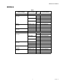
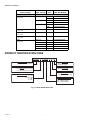
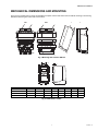
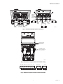
SmartVFD COMPACT
PRODUCT DATA
• Overtemperature ride-through
• Power ride-through
• Automatic restart
• Integrated PI controller
• Optional NEMA 1 enclosure
SPECIFICATIONS
Mains Connection
GENERAL
SmartVFD COMPACT variable frequency drives provide step
less speed control for various applications:
•
•
•
•
Pumps
Fans
Compressors
Conveyors, etc.
FEATURES
• Compact size - saves space in your equipment cabinet
• Flexible side-by-side mounting with screws or DIN-rail
as standard
Input voltage Uin:
115Vac, -15%...+10% 1~
208…240 Vac (-15…+10%), 1~
208…240 Vac (-15…+10%), 3~
380…480 Vac (-15…+10%), 3~
600Vac (-15…+10%), 3~
Input frequency: 45…66 Hz
Connection to mains: Once per minute or less
Brake chopper:
Available on MI2 and MI3, with 3-phase units: 100% *TN with
brake option; 30% *TN without brake option.
Motor Connection
Output voltage: 0 - Uin, 3~
Output current:
IN: Continuous output current with max. +50 °C ambient temperature, overloadability 1.5 x IN (1min/10min)
Starting current: 2 x IN 2s/20s
• Single rating suitable for both pump and fan or
machine applications
Output frequency: 0…320 Hz
• Maximum ambient temperature: + 122 °F
Frequency resolution: 0.01 Hz
• Integrated RFI-filters
• Wide input and output connection possibilities
• Configurable inputs and outputs
Control Characteristics
• 30 second Start-Up Wizard
Control method:
Frequency Control U/f Open Loop Sensorless Vector Control
• Easy “keypad to remote” change with 1 button
Switching frequency: 1.5...16 kHz; default 6 kHz
• Parameter upload/download even without main power
to the drive with HVFDCABLE accessory
Field weakening point: 30…320 Hz
• Quiet motor operation with 4 kHz switching frequency
Acceleration time: 0.1…3000 sec
31-00075-01
SMARTVFD COMPACT
Deceleration time: 0.1…3000 sec
Safety:
Braking torque:
100% *TN with brake option (only in 3~ drives sizes MI2
and MI3)
30%*TN without brake option
For safety: CB, CE, UL, cUL
Ambient Conditions
Control connections
Operating temperature:
+ 14 °F (-10 °C) (no frost)…+ 104/122 °F
(40/50 °C) for 115 Vac, 460 Vac and 600 Vac and + 104 °F
(40 °C), for 208 Vac/230 Vac, rated loadability IN
Analog input voltage:
0...+10V, Ri = 200kΩ (min), Resolution 10 bit, accuracy ±1%,
electrically isolated
For EMC: CE, CB, c-tick
(see unit nameplate for more detailed approvals)
Analog input current:
0(4)…20 mA, Ri = 200Ω differential resolution 0.1%, accuracy
±1%, electrically isolated
Storage temperature: -40 °F (-40 °C)…+158 °F (+70 °C)
Air quality:
Chemical vapors:
IEC 721-3-3, unit in operation, class 3C2
Mechanical particles:
IEC 721-3-3, unit in operation, class 3S2
Altitude:
100% load capacity (no derating) up to 1000 m
1% derating for each 100 m above 1000 m; max. 2000 m
Digital inputs: 6 positive logic; 0…+30 VDC
Voltage output for digital inputs:
+24V, ±20%, max. load 50 mA
Output reference voltage:
+10V, +3%, max. load 10 mA
Analog output:
0(4)…20 mA; RL max. 500Ω; resolution 16 bit; accuracy ±1%
Relative humidity:
0…95% RH, non-condensing, non-corrosive, no dripping
water
Digital outputs:
Relays:
2 programmable relay outputs (1 NO/NC and 1 NO),
Max.switching load: 250 Vac/2 A or 250 Vdc/0.4 A
Open collector:
1 open collector output with max. load 48 V/50 mA
Vibration: 3...150 Hz
EN50178, EN60068-2-6:
Displacement amplitude 1(peak) mm at 3...15.8 Hz
Max acceleration amplitude 1 g at 15.8...150 Hz
Protections
Shock
EN50178, IEC 68-2-27:
UPS Drop Test (for applicable UPS weights)
Overvoltage protection:
875VDC in HVFDCDXCXXXXXXX
437VDC in HVFDCDXBXXXXXXX
Storage and shipping: max 15 g, 11 ms (in package)
Undervoltage protection:
333VDC in HVFDCDXCXXXXXXX
160VDC in HVFDCDXBXXXXXXX
Enclosure class: Open chassis, NEMA 1 kit optional
Electro Magnetic Compatibility
(EMC)
Earth-fault protection:
In case of earth fault in motor or motor cable, only the frequency converter is protected
Immunity:
Complies with EN50082-1, -2, EN61800-3, Category C2
Unit overtemperature protection: YES
Emissions:
115V: Complies with EMC category C4
230V: Complies with EMC category C2; with an internal RFI
filter
400V: Complies with EMC category C2; with an internal RFI
filter
600V: Complies with EMC category C4
All: No EMC emission protection (Honeywell level N): Without
RFI filter
Motor overload protection: YES
Motor stall protection (fan/pump blocked): YES
Motor underload protection
(pump dry / belt broken detection): YES
Short-circuit protection of +24V and +10V
reference voltages: YES
Overcurrent protection: Trip limit 4,0*IN instantaneously
31-00075—01
2
SMARTVFD COMPACT
MODELS
Table 1.
Nominal Voltage
Nom. HP
(Nom. Current)
EMC
Filter
Full IO (6DI, 2AI, 1AO,
1DO, 3RO, Modbus)
Frame Size: MI1
Dimensions: 6.2" H x 2.6" W x 3.9" D
460V
3~in 3~out
0.5 HP (1.3 A)
0.75 HP (1.9 A)
1 HP (2.4 A)
208/230V
1~in 3~out
No
HVFDCD3C0005F00
EMC
HVFDCD3C0005F01
No
HVFDCD3C0007F00
EMC
HVFDCD3C0007F01
No
HVFDCD3C0010F00
EMC
HVFDCD3C0010F01
0.25 HP (1.7 A)
EMC
HVFDCD1B0003F01
0.5 HP (2.4 A)
EMC
HVFDCD1B0005F01
0.75 HP (2.8 A)
EMC
HVFDCD1B0007F01
208/230V
3~in 3~out
0.25 HP (1.7 A)
No
HVFDCD3B0003F00
0.5 HP (2.4 A)
No
HVFDCD3B0005F00
Frame Size: MI2
Dimensions: 7.7" H x 3.5" W x 4.0" D
460V
3~in 3~out
1.5 HP (3.3 A)
2 HP (4.3 A)
3 HP (5.6 A)
208/230V
1~in 3~out
No
HVFDCD3C0015F00
EMC
HVFDCD3C0015F01
No
HVFDCD3C0020F00
EMC
HVFDCD3C0020F01
No
HVFDCD3C0030F00
EMC
HVFDCD3C0030F01
1 HP (3.7A)
EMC
HVFDCD1B0010F01
1.5 HP (4.8 A)
EMC
HVFDCD1B0015F01
2 HP (7 A)
EMC
HVFDCD1B0020F01
208/230V
3~in 3~out
1 HP (3.7A)
No
HVFDCD3B0010F00
2 HP (7 A)
No
HVFDCD3B0020F00
115V/230V
1~in 3~out
0.25 HP (1.7 A)
No
HVFDCD1A0003F00
0.5 HP (2.4 A)
No
HVFDCD1A0005F00
1 HP (3.7A)
No
HVFDCD1A0010F00
3
31-00075—01
SMARTVFD COMPACT
Nom. HP
(Nom. Current)
Nominal Voltage
EMC
Filter
Full IO (6DI, 2AI, 1AO,
1DO, 3RO, Modbus)
Frame Size: MI3
Dimensions: 10.2" H x 3.9" W x 4.3" D
460V
3~in 3~out
4 HP (7.6 A)
No
HVFDCD3C0040F00
EMC
HVFDCD3C0040F01
5 HP (9 A)
No
HVFDCD3C0050F00
EMC
HVFDCD3C0050F01
7.5 HP (12 A)
No
HVFDCD3C0075F00
EMC
HVFDCD3C0075F01
208/230V
1~in 3~out
3 HP (1 A)
EMC
HVFDCD1B0030F01
208/230V
3~in 3~out
3 HP (11 A)
No
HVFDCD3B0030F00
115V/230V
1~in 3~out
1.5 HP (4.8 A)
No
HVFDCD1A0015F00
600V
3~in 3~out
1 HP (2 A)
No
HVFDCD3D0010F00
2 HP (3.6 A)
No
HVFDCD3D0020F00
3 HP (5 A)
No
HVFDCD3D0030F00
5 HP (7.6 A)
No
HVFDCD3D0050F00
7.5 HP (10.4 A)
No
HVFDCD3D0075F00
PRODUCT IDENTIFICATION CODE
HVFDCD 3 C 0000 F 0 0
PRODUCT FAMILY
HVFDCD = SmartVFD COMPACT
EMC FILTER
0 = NO FILTER
1 = FILTER INCLUDED
PHASES
1 = SINGLE PHASE (1~IN, 3~OUT)
3 = TRIPLE PHASE (3~IN, 3~OUT)
ENCLOSURE
0 = OPEN CHASSIS (IP20)
CONTROL IO
F = FULL IO (6DI, 1A2, 3DO, 1AO)
NOMINAL VOLTAGE
A = 115V
B = 208V-230V
C = 480V
D = 600V
NOMINAL HORSE POWER
0007 = .75 HORSE POWER
0010 = 1 HORSE POWER
0100 = 10 HORSE POWER
M35443
Fig. 1. Product Identification Code.
31-00075—01
4
SMARTVFD COMPACT
MECHANICAL DIMENSIONS AND MOUNTING
There are two possible ways to mount the SmartDrive Compact onto the wall; either screw or DIN-rail mounting. The mounting
dimensions are also given on the back of the inverter.
MI1
1
MI2-3
2
M35444
Fig. 2. Mounting with screws or DIN-rail.
W2
W3
H1
D2
H2
H3
D1
W1
Mechanical size
MI1
H1
H2
H3
W1
M35445
W2
W3
D1
D2
6.2
5.8
5.4
2.6
1.5
0.2
3.9
0.3
MI2
7.7
7.2
6.7
3.5
2.5
0.2
4.0
0.3
MI3
10.3
9.9
9.5
3.9
3.0
0.2
4.3
0.3
Fig. 3. Dimensions in inches.
5
31-00075—01
SMARTVFD COMPACT
COOLING
Forced air flow cooling is used in all SmartDrive Compact drives. Enough free space shall be left above and below the inverter to
ensure sufficient air circulation and cooling. SmartDrive Compact products can be mounted side by side. You will find the required
dimensions for free space and cooling air in the tables below:
Table 2.
Mechanical size
Free space above [inches]
Free space below [inches]
MI1
4.0
2.0
MI2
4.0
2.0
MI3
4.0
2.0
Table 3.
Mechanical size
Cooling air required [CFM]
MI1
5.89
MI2
5.89
MI3
17.7
CABLING AND FUSES
Use cables with heat resistance of at least +158 °F (+70 °C). The cables and the fuses must be dimensioned according to the
following tables. The fuses function also as cable overload protection. These instructions apply only to cases with one motor and
one cable connection from the inverter to the motor. In any other case, contact your Honeywell Sales Representative.
Table 4.
Connection
Cable type
Mains cable
Power cable intended for fixed installation and the specific mains voltage. Shielded cable not required.
(NKCABLES/MCMK or similar recommended)
Motor cable
Power cable equipped with compact low-impedance shield and intended for the specific mains voltage.
(NKCABLES /MCCMK, SAB/ÖZCUY-J or similar recommended). 360º grounding of both motor and FC
connection required to meet the standards.
Control cable
Screened cable equipped with compact low-impedance shield (NKCABLES /Jamak, SAB/ÖZCuY-O or
similar).
Table 5. Cable and fuse sizes for 208-240 V.
Terminals cable size (min/max)
Size
IN
[A]
Type
(power)
Fuse
[A]
Mains cable Cu
[AWG]
Main
terminal
[AWG]
Earth
terminal
[AWG]
Control
terminal
[AWG]
Relay
terminal
[AWG]
MI1
P25 - P75
1,7 – 3,7
10
2 x 15 + 15
15 - 11
15 - 11
20 - 15
20 - 15
MI2
1P1 - 1P5
4,8 – 7,0
20
2 x 13 + 13
15 - 11
15 - 11
20 - 15
20 - 15
MI3
2P2
11
32
2x9+9
15 - 9
15 - 9
20 - 15
20 - 15
Table 6. Cable and fuse sizes for 380-480 V.
Terminals cable size (min/max)
Size
Type
(power)
IN
[A]
Fuse
[A]
Mains cable Cu
[AWG]
Main
terminal
[AWG]
Earth
terminal
[AWG]
Control
terminal
[AWG]
Relay
terminal
[AWG]
MI1
P37 - 1P1
1,9 – 3,3
6
3 x 15 + 15
15 - 11
15 - 11
20 - 15
20 - 15
MI2
1P5 - 2P2
4,3 – 5,6
10
3 x 15 + 15
15 - 11
15 - 11
20 - 15
20 - 15
MI3
3P0 - 5P5
7,6 - 12
20
3 x 13 + 13
15 - 9
15 - 9
20 - 15
20 - 15
31-00075—01
6
SMARTVFD COMPACT
3~ (400V)
3~ (400V)
1~ (230V)
EXTERNAL BRAKE
RESISTOR (400V)
MOTOR OUT
L1 L2/N L3 R+ R- U/T1 V/T2 W/T3
1~ (230V)
MOTOR OUT
L1 L2/N L3
U/T1 V/T2 W/T3
STRIP THE
PLASTIC
CABLE
COATING
FOR 360°
GROUNDING
BRAKE
RESISTOR
MAINS
MAINS
STRIP THE
PLASTIC CABLE
COATING FOR
360° GROUNDING
MOTOR
MOTOR
M35446
Fig. 4. SmartDrive Compact power connections.
CONTROL CABLE
TIGHTENING
TORQUE: 0.4 Nm
STRIP THE PLASTIC
CABLE COATING FOR
360° GROUNDING
M35447
Fig. 5. SmartDrive Compact control connections wiring.
A12 GND GND DI4
13
5
4
14
DI5
DI6
AO
DO
RO1
15
16
18
20
22
1
2
3
6
7
8
9
10
+10V
AI1
GND
24V
GND
DI1
DI2
DI3
RO1
–
RO2
26
23
25
A
B
24
RO2 RO2
M35448
Fig. 6. SmartVFD Compact control connection terminals.
7
31-00075—01
SMARTVFD COMPACT
The table below shows the SmartDrive Compact control connections with the terminal numbers.
API FULL
FACTORY PRESET
TERMINAL SIGNAL
1 +10Vre REF. VOLTAGE OUT
2 Al1
ANALOG SIGNAL FREQ. REFERENCE P)
IN 1
3 GND
I/O SIGNAL GROUND
6 24Vout 24V OUTPUT FOR
DI’S
I/O SIGNAL GROUND
7 GND
mA
8 DI1
DIGITAL INPUT 1
START FORWARDP)
9 DI2
DIGITAL INPUT 2
START REVERSEP)
10
A
B
4
DI3
A
B
Al2
PRESET SPEED BOP)
FB COMMUNICATION
FB COMMUNICATION
5
13
14
15
GND
GND
DI4
DIGITAL INPUT 3
RS485 SIGNAL A
RS485 SIGNAL B
ANALOG SIGNAL IN 2
I/O SIGNAL GROUND
I/O SIGNAL GROUND
DIGITAL INPUT 4
DI5
DIGITAL INPUT 5
FAULT RESET P)
16 DI6
DIGITAL INPUT 6
DISABLE PI CONTR.P)
18 AO
20 DO
22 RO 11
23 RO 12
24 RO 21
25 RO 22
26 RO 23
PI ACTUAL VALUE P)
DESCRIPTION
MAXIMUM LOAD 10 mA
0 – + 10 V Ri = 200 k Ω (MIN)
±20% MAX LOAD 50 mA
0 – + 30 V Ri = 12 k Ω (MIN)
0(4) – 20 mA, Ri = 200 k Ω
PRESET SPEED B1 P) 0 – + 30 V Ri = 12 k Ω (MIN)
OUTPUT FREQUENCY P) 0(4) – 20 mA, RL = 500Ω
OPEN COLLECTOR,
ACTIVE = READY P)
MAX. LOAD 48V/50mA
P)
MAX. SWITCHING
RELAY OUT 1 ACTIVE = RUN
LOAD: 250Vac/2A OR
250Vdc/0.4A
RELAY OUT 2 ACTIVE = FAULT P)
MAX. SWITCHING
LOAD: 250Vac/2A OR
250Vdc/0.4A
DIGITAL SIGNAL OUT
P) = PROGRAMMABLE FUNCTION, SEE USER MANUAL, PARAMETERS
M35449
Fig. 7. Control inputs and outputs – API Full.
FEATURES / FUNCTIONS
Easy to set-up features
Table 7.
Feature
Functions
Benefit
30 second Start-up wizard
Simple 4 step wizard for specific applications
Activate wizard by pressing stop for 5 seconds
Tune the motor nominal speed
Tune the motor nominal current
Select mode (0=basic, 1= Fan, 2 = Pump and 3 = Conveyor)
Fully configured inverter for
the application in question
Ready to accept 0-10V
analog speed signal in just
30 seconds
“Keypad – Remote”
Operation
Push the navigation wheel for 5 seconds to move from remote
control (I/O or Fieldbus) to manual mode and back.
Single button operation to
change the control to
manual (keypad) and back.
Useful function when
commissioning and testing
applications
Quick Setup Menu
Only the most commonly used parameters are visible in basic view Easy navigation through the
to provide easier navigation. The full view can be seen after P13.1 most common parameters
Parameter conceal is deactivated by changing the value to 0.
SmartVFD Commissioning
Tool
31-00075—01
1. Parameter sets can be uploaded and downloaded with this
tool.
2. Easy to use PC-tool for commissioning the SmartVFD Inverters. Connection with HVFDCABLE and MCA adapter, (HVFDCDMCAKIT/U), to the USB port of the PC. PC-tools available
for download free of charge from
https://customer.honeywell.com/en-US/support/commercial/
software/vfds/Pages/default.aspx
8
Parameter copying easily
from 1 inverter to another.
Easy download of parameter
sets created with PC-tool
Parametering with PC
Saving settings to PC
Comparing parameter
settings
SMARTVFD COMPACT
Compact and robust design with easy installation
Table 8.
Feature
Functions
Benefit
Compact size
Minimum free space above and below the drive is required for
cooling airflow.
Minimum space requirements
Integrated RFI-filters
The units comply with EN61800-3 category C2 as standard. This
level is the required level for public electricity networks such as
buildings.
Easy selection and
installation of products.
Space savings
Cost savings
Single power rating
Single power suitable for both pump and fan or machine
applications
Easy selection
Max. ambient temperature
+ 122 °F
High maximum ambient operating temperature
Uninterruptible operation
Side by side mounting with SmartDrive Compact can be mounted side by side with no space Easy installation
between the units either with screws or on DIN-rail as standard.
Space savings
screws or DIN-rail as
Dimensions for screw mounting can be found also on the back of
standard
the inverter.
Uninterruptible operation functions
Table 9.
Feature
Functions
Benefit
Overtemperature
ride-through
Automatically adjusts switching frequency to adapt to unusual
increase in ambient
Power ride-through
Automatically lowers motor speed to adapt to sudden voltage drop Uninterruptible operation
such as power loss
Auto restart function
Auto restart function can be configured to make VFD restart
automatically once fault is addressed
Uninterruptible operation
Uninterruptible operation
VFD and motor control features
Table 10.
Feature
Functions
Benefit
Flying start
Ability to get an already spinning fan under speed control
Improved performance
Ease of application
Inbuilt PI- controller
Capability to make a standalone system with sensor connected
directly to the inverter for complete PI- control.
Cost saving
OPTIONAL ACCESSORIES
Table 11. SmartVFD COMPACT Accessories.
Model Number
HVFDCABLE/U
Description
SmartVFD Commissioning Cable and USB Adaptor
HVFDCDMCA/U
Compact Commissioning Device
HVFDCDMCAKIT/U
Compact Commissioning Kit
HVFDCDNEMA1FR1/U
Compact NEMA 1 Kit Frame Size1
HVFDCDNEMA1FR2/U
Compact NEMA 1 Kit Frame Size2
HVFDCDNEMA1FR3/U
Compact NEMA 1 Kit Frame Size3
HVFDCDTRAINER/U
Compact Training Demonstration Kit
9
31-00075—01
SMARTVFD COMPACT
31-00075—01
10
SMARTVFD COMPACT
11
31-00075—01
SMARTVFD COMPACT
By using this Honeywell literature, you agree that Honeywell will have no liability for any damages arising out of your use or modification
to, the literature. You will defend and indemnify Honeywell, its affiliates and subsidiaries, from and against any liability, cost, or damages,
including attorneys’ fees, arising out of, or resulting from, any modification to the literature by you.
Automation and Control Solutions
Honeywell International Inc.
1985 Douglas Drive North
Golden Valley, MN 55422
customer.honeywell.com
® U.S. Registered Trademark
© 2015 Honeywell International Inc.
31-00075—01 M.S. 01-15
Printed in United States