1
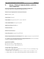
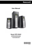
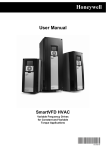
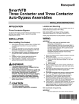
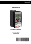
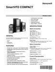
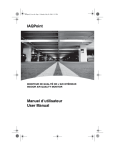
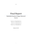
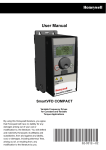
Honeywell BACnet Protocol Installation and User’s Manual SmartVFD HVAC Variable Frequency Drives for Constant and Variable Torque Applications By using this Honeywell literature, you agree that Honeywell will have no liability for any damages arising out of your use or modification to, the literature. You will defend and indemnify Honeywell, its affiliates and subsidiaries, from and against any liability, cost, or damages, including attorneys’ fees, arising out of, or resulting from, any modification to the literature by you. 63-2697-03 Honeywell • 0 INDEX Document: DPD00267A Version release date: 12.11.09 1. Safety ..................................................................................................................2 1.1 1.2 1.3 Danger ............................................................................................................................ 2 Warnings......................................................................................................................... 3 Grounding and ground fault protection ........................................................................... 3 2. 3. BACnet - general info ........................................................................................6 BACnet technical data.......................................................................................8 3.1 3.2 BACnet MS/TP protocol.................................................................................................. 8 BACnet IP protocol ......................................................................................................... 8 4. BACnet installation..........................................................................................10 4.1 4.2 Prepare for use through ethernet.................................................................................. 11 Prepare for use through MS/TP .................................................................................... 13 5. Programming ...................................................................................................16 5.1 5.2 5.2.1 5.2.2 5.3 5.3.1 5.3.2 5.4 5.4.1 5.4.2 5.4.3 BACnet MS/TP parameters and monitoring values (M5.7.3)........................................ 16 BACnet IP parameters and monitoring values.............................................................. 18 Ethernet common settings (M5.8.1).............................................................................. 18 BACnet IP settings........................................................................................................ 18 BACnet MS/TP parameter descriptions ........................................................................ 19 BACnet MS/TP Parameters .......................................................................................... 19 BACnet MS/TP monitoring values ................................................................................ 20 BACnet IP parameter descriptions................................................................................ 21 Ethernet common settings ............................................................................................ 21 BACnet IP settings........................................................................................................ 22 IP monitoring values ..................................................................................................... 22 6. Communications..............................................................................................24 6.1 6.1.1 6.1.2 6.2 6.3 Object types and properties supported ......................................................................... 24 Binary Value Object ...................................................................................................... 25 Analog Value Object ..................................................................................................... 27 Control word bits ........................................................................................................... 29 Status word bits ............................................................................................................ 29 7. Fault tracing .....................................................................................................30 7.1 7.2 Typical fault conditions.................................................................................................. 30 Other fault conditions .................................................................................................... 31 8. 9. Quick setup ......................................................................................................34 Annex - Protocol implementation conformance statement.........................36 Honeywell • 1 Safety 1. Honeywell • 2 Safety This manual contains clearly marked cautions and warnings which are intended for your personal safety and to avoid any unintentional damage to the product or connected appliances. Please read the information included in cautions and warnings carefully. The cautions and warnings are marked as follows: = DANGER! Dangerous voltage = WARNING or CAUTION = Caution! Hot surface Table 1. Warning signs 1.1 Danger The components of the power unit of the Smart VFD are live when the VFD is connected to mains potential. Coming into contact with this voltage is extremely dangerous and may cause death or severe injury. The motor terminals U, V, W and the brake resistor terminals are live when the drive is connected to mains, even if the motor is not running. After disconnecting the VFD from the mains, wait until the indicators on the keypad go out (if no keypad is attached see the indicators on the cover). Wait 5 more minutes before doing any work on the connections of the drive. Do not open the cover before this time has expired. After expiration of this time, use a measuring equipment to absolutely ensure that no voltage is present. Always ensure absence of voltage before starting any electrical work! The control I/O-terminals are isolated from the mains potential. However, the relay outputs and other I/O-terminals may have a dangerous control voltage present even when the drive is disconnected from mains. Before connecting the VFD to mains make sure that the front and cable covers of the drive are closed. During a ramp stop (see the Application Manual), the motor is still generating voltage to the drive. Therefore, do not touch the components of the VFD before the motor has completely stopped. Wait until the indicators on the keypad go out (if no keypad is attached see the indicators on the cover). Wait additional 5 minutes before starting any work on the drive. Honeywell • 3 1.2 Safety Warnings The Honeywell Smart VFD is meant for fixed installations only. Do not perform any measurements when the VFD is connected to the mains. The ground leakage current of the Honeywell Smart VFD exceeds 3.5mA AC. According to standard EN61800-5-1, a reinforced protective ground connection must be ensured. See chapter 1.3. If the VFD is used as a part of a machine, the machine manufacturer is responsible for providing the machine with a supply disconnecting device (EN 60204-1). Only spare parts delivered by Honeywell can be used. At power-up, power brake or fault reset the motor will start immediately if the start signal is active, unless the pulse control for Start/Stop logic has been selected. Futhermore, the I/O functionalities (including start inputs) may change if parameters, applications or software are changed.Disconnect, therefore, the motor if an unexpected start can cause danger. The motor starts automatically after automatic fault reset if the auto restart function is activated. See the Application Manual for more detailed information. Prior to measurements on the motor or the motor cable, disconnect the motor cable from the VFD. Do not touch the components on the circuit boards. Static voltage discharge may damage the components. Check that the EMC level of the VFD corresponds to the requirements of your supply network. 1.3 Grounding and ground fault protection CAUTION! The Honeywell Smart VFD must always be grounded with a ground conductor to the ground terminal marked with . The earth leakage current of the drive exceeds 3.5mA AC. According to EN61800-5-1, one or more of the following conditions for the associated protective circuit shall be satisfied: a) The protective conductor shall have a cross-sectional area of at least 10 mm2 Cu or 16 mm2 Al, through its total run. b) Where the protective conductor has a cross-sectional area of less than 10 mm2 Cu or 16 mm2 Al, a second protective conductor of at least the same cross-sectional area shall be provided up to a point where the protective conductor has a cross-sectional area not less than 10 mm2 Cu or 16 mm2 Al. c) Automatic disconnection of the supply in case of loss of continuity of the protective conductor. Safety Honeywell • 4 The cross-sectional area of every protective grounding conductor which does not form part of the supply cable or cable enclosure shall, in any case, be not less than: - 2.5mm2 if mechanical protection is provided or - 4mm2 if mechanical protection is not provided. The ground fault protection inside the VFD protects only the drive itself against earth faults in the motor or the motor cable. It is not intended for personal safety. Due to the high capacitive currents present in the VFD, fault current protective switches may not function properly. Do not perform any voltage withstand tests on any part of the drive. There is a certain procedure according to which the tests shall be performed. Ignoring this procedure may result in damaged product. Honeywell • 5 Safety BACnet - general info 2. Honeywell • 6 BACnet - general info BACnet stands for ‘Building Automation and Control Networks’. It is the common name for the communication standard ISO 16484-5 which defines the methods and the protocol for cooperating building automation devices to communicate. Devices can be designed to operate using BACnet communication protocol as well as utilising BACnet protocol to communicate between systems. BACnet is an internationally accepted protocol for building automation (e.g. lightning control, air conditioning and heating automation) and control over a communications network. BACnet provides a method by which computer-based control equipment, from different manufacturers can work together, or 'interoperate'. For this to be achieved, components must be able to exchange and understand BACnet data messages. Your Honeywell Smart VFD is equipped with BACnet support as standard. BACnet IP - Ethernet BACnet IP Switch Ethernet to MS/TP Router BACnet MS/TP Figure 1.Principal example diagram of BACnet Honeywell • 7 BACnet - general info BACnet technical data Honeywell • 8 3. BACnet technical data 3.1 BACnet MS/TP protocol Interface Data transfer method Transfer cable Connections and Connector communications Electrical isolation BACnet MS/TP Baud rate RS-485 RS-485 MS/TP, half-duplex STP (Shielded Twisted Pair), type Belden 9841 or similar 2.5 mm2 Functional As described in ANSI/ASHRAE Standards 135-2004 9600, 19200, 38400 and 76800 baud(supports autobaud detection) Table 2. 3.2 BACnet IP protocol Interface Data transfer method Data transfer speed Protocol Connections and Connector communications Cable type BACnet IP Default IP 100BaseTX, IEEE 802.3 compatible Ethernet half/full -duplex 10/100 MBit/s, autosensing BACnet over UDP/IP Shielded RJ45 connector CAT5e STP As described in ANSI/ASHRAE Standards 135-2004 Selectable: Fixed or DHCP Table 3. Honeywell • 9 BACnet technical data BACnet installation 4. Honeywell • 10 BACnet installation 1 Open the cover of the VFD. The relay outputs and other I/O-terminals may have a dangerous control voltage present even when the drive is disconnected from mains. DANGER Figure 2. 2 Locate the components that you will need on the VFD to connect and run the BACnet cables. Be sure not to plug the Ethernet/BACnet IP cable to the terminal under the keypad! This might harm your personal computer. WARNING Honeywell • 11 BACnet installation DIP switches RS485 terminals 21 22 23 Ethernet connector 24 25 26 32 33 12 13 14 15 16 17 18 19 30 A B Ethernet cable run conduit 1 2 3 4 5 6 7 8 9 10 11 I/O terminal (see larger picture) Grounding bar Figure 3. You can use the BACnet communication protocol through Ethernet and RS485. 4.1 Prepare for use through ethernet 3 Connect the Ethernet cable (see specification on page 8) to its terminal and run the cable through the conduit as shown in Figure 4. Ethernet cable Figure 4. BACnet installation 4 Honeywell • 12 Cut the VFD cover opening for the Ethernet cable (NEMA 1 enclosure). Figure 5. 5 Remount the VFD cover. NOTE: When planning the cable runs, remember to keep the distance between the Ethernet cable and the motor cable at a minimum of 30 cm. Ethernet cable Figure 6. Honeywell • 13 4.2 BACnet installation Prepare for use through MS/TP Strip about 15 mm of the RS485 cable (see specification on page 8) and cut off the grey cable shield. Remember to do this for both bus cables (except for the last device). Leave no more than 10 mm of the cable outside the terminal block and strip the cables at about 5 mm to fit in the terminals. See picture below. 10 3 4 5 Also strip the cable now at such a distance from the terminal that you can fix it to the frame with the grounding clamp. Strip the cable at a maximum length of 15 mm. Do not strip the aluminum cable shield! Then connect the cable to its appropriate terminals on Honeywell Smart VFD standard terminal block, terminals A and B (A = negative, B = positive). See Figure 7. RS485 terminals (A and B) 21 22 23 24 25 26 2829 20 A B 12 13 14 15 16 17 18 19 20 A B 1 2 3 4 5 6 7 8 9 10 11 8 9 10 11 Figure 7. BACnet installation Honeywell • 14 Using the cable clamp included in the delivery of the drive, ground the shield of the RS485 cable to the frame of the VFD. Cable clamp 5 If the drive is the last device on the bus, the bus termination must be set. Locate the DIP switches to the right of the control keypad of the drive and turn the switch for the RS485 bus termination resistor to position ON. Biasing is built in the termination resistor. See also step 9 on page 15. 6 ON Current Current Current RS485* AO1 AI2 AI1 * Bus termination resistor OFF Voltage Voltage Voltage Honeywell • 15 BACnet installation Unless already done for the other control cables, cut free the opening on the VFD cover for the RS485 cable (protection class IP21). 7 Remount the VFD cover and run the RS485 cables as shown in picture. NOTE: When planning the cable runs, remember to keep the distance between the fieldbus cable and the motor cable at a minimum of 30 cm. 8 RS485 cables The bus termination must be set for the first and the last device of the fieldbus line. See picture below. See also step 6 on page 14. We recommend that the first device on the bus and, thus, terminated was the Master device. 9 Termination activated BACnet MS/TP = Bus termination Termination deactivated Termination activated with DIP switch Programming 5. Honeywell • 16 Programming Basic information on how to use the control keypad you will find in the Application Manual. The navigation path to the fieldbus parameters may differ from application to application. The exemplary paths below apply to the Honeywell Smart VFD. 1. First ensure that the right fieldbus protocol is selected. Navigate: Main Menu > I/O and Hardware (M5) > RS-485 (M5.7) OR Ethernet (M5.8) > Common settings (M5.7.1) > Protocol (P5.7.1.1) > Edit > (Choose protocol) 2. Select ‘Fieldbus control’ as the Remote Control Place. Navigate: Main Menu > Quick Setup (M1) > Rem. Ctrl. Place (P1.15) OR Navigate: Main Menu > Parameters (M3) > Start/Stop Setup (M3.2) > Rem. Ctrl. Place (P3.2.1) 3. Choose source of reference. Navigate: Main Menu > Parameters (M3) > References (M3.3) 4. Set fieldbus parameters (M5.7 and M5.8). See below. 5.1 Code BACnet MS/TP parameters and monitoring values (M5.7.3) Parameter Min Max Unit Default ID Description PARAMETERS P5.7.3.1.1 Baud rate 1 4 bd 1 Communication speed 1 = 9600 2 = 19200 3 = 38400 4 = 76800 Automatic baudrate detection 0 = Off 1 = On; The automatically detected baud rate is then shown as value of parameter P5.7.3.1.1 P5.7.3.1.2 Autobauding 0 1 1 P5.7.3.1.3 MAC address 1 127 1 P5.7.3.1.4 Instance number 0 65535 P5.7.3.1.5 Communication time-out 0 65535 s 0 Device Object's instance number. 0 = Automatically gegerated 10 0 = Not used Honeywell • 17 Code Programming Parameter Min Max 1 3 Unit Default ID Description MONITORING VALUES P5.7.3.2.1 Fieldbus protocol status 1 = Stopped 2 = Operational 3 = Faulted 0-99 Number of messages with errors 0-999 Number of messages without communication errors P5.7.3.2.2 Communication status 0.0 99.999 0.0 P5.7.3.2.3 Actual instance number 0 65535 Serial number Shows actual Device Object's instance number 0 0 = None 1 = Sole Master 2 = Duplicate MAC ID 3 = Baud rate fault P5.7.3.2.4 Fault code 0 3 P5.7.3.2.5 Control word hex See chapters 6.2 and 6.3. P5.7.3.2.6 Status word hex See chapters 6.2 and 6.3. Table 4. Parameters related with BACnet used through MS/TP Programming Honeywell • 18 5.2 BACnet IP parameters and monitoring values 5.2.1 Ethernet common settings (M5.8.1) Code Parameter Min Max Unit Default ID Description P5.8.1.1 IP address mode See page 21. P5.8.1.2 IP address See page 21. P5.8.1.3 Subnet mask See page 21. P5.8.1.4 Default gateway See page 21. P5.8.1.5 MAC address See page 21. Table 5. Common settings for BACnet IP 5.2.2 Code BACnet IP settings Parameter Min Max Unit Default ID Description PARAMETERS P5.8.3.1.1 Instance number 0 4194304 P5.8.3.1.2 Communication time-out 0 65535 P5.8.3.1.3 Protocol in use 0 1 1 3 s 0 Device Object’s instance number 0 = Serial number 0 0 = Not used 0 0 = Not used 1 = Used MONITORING VALUES P5.8.3.2.1 Fieldbus protocol status 1 = Stopped 2 = Operational 3 = Faulted 0-99 Number of messages with errors 0-999 Number of messages without communication errors P5.8.3.2.2 Communication status 0.0 99.999 0.0 P5.8.3.2.3 Actual instance number 0 65535 Serial number P5.8.3.2.4 Control word hex See chapters 6.2 and 6.3. P5.8.3.2.5 Status word hex See chapters 6.2 and 6.3. Shows actual Device Object's instance number Table 6. Parameters related with BACnet used through Ethernet Honeywell • 19 Programming 5.3 BACnet MS/TP parameter descriptions 5.3.1 BACnet MS/TP Parameters P5.7.3.1.1 BAUD RATE Select the communication speed for the network. The default value is 9600 baud. If value Auto is chosen this parameter is not editable. P5.7.3.1.2 AUTOBAUDING This function is set off by default. If the parameter is given value 1 the automatic baud rate detection is used. The automatically detected baud rate is then shown as value of parameter P5.7.3.1.1 Baud rate. P5.7.3.1.3 MAC ADDRESS The parameters of every device must be set before connecting to the bus. Especially the parameters MAC address and Baud rate must be the same as in the master’s configuration. The first parameter, MAC (Medium Access Control) address, must be unique on the network to which it is connected. The same MAC address may be used on a device on another network within the internetwork. Addresses 128-254 are reserved for slaves. Addresses 1-127 are valid for both masters and slaves. The portion of the address space that is actually used for masters in a particular installation is determined by the value of the Max_Master property of the Device object. It is recommended that MAC address 0 be reserved for use by the MS/TP router. 255 is reserved for broadcasts. P5.7.3.1.4 INSTANCE NUMBER The Device Object's Instance number must be unique across the entire BACnet internetwork because it is used to uniquely identify the BACnet devices. It may be used to conveniently identify the BACnet device from other devices during installation. If 0 (default) is selected, the Device Instance number is read from the VFD. This unique number is then shown in the Monitor menu. If any other value than zero is selected, the value is used as Device Object's Instance number. The actual value is shown in the Monitor menu. The default value for this parameter is generated from the Ethernet MAC address. Last 2 octets will be used. XX.XX.XX.XX.FF.FF. P5.7.3.1.5 COMMUNICATION TIME-OUT BACnet board initiates a communication error if the board is a "sole master" in the network for a time defined with this parameter. ‘0’ means that no fault is generated. Programming 5.3.2 Honeywell • 20 BACnet MS/TP monitoring values P5.7.3.2.1 FIELDBUS PROTOCOL STATUS Fieldbus Protocol Status tells the status of the protocol. P5.7.3.2.2 COMMUNICATION STATUS The Communication status shows how many error and how many good messages the frequency converter has received. The Communication status includes a common error counter that counts CRC and parity errors and a counter for good messages. Only messages to the current slave in use are counted in the good messages, not MS/TP token packages. Good messages 0…999 Number of messages received without errors Bad Frames 0…99 Number of messages received with errors Table 7. P5.7.3.2.3 ACTUAL INSTANCE NUMBER Shows the actual instance number. P5.7.3.2.4 FAULT CODE Shows BACnet MS/TP fault codes. P5.7.3.2.5 CONTROL WORD Shows the Control Word received from the bus. P5.7.3.2.6 STATUS WORD Shows the current Status Word that is sent to the bus. Honeywell • 21 Programming 5.4 BACnet IP parameter descriptions 5.4.1 Ethernet common settings P5.8.1.1 IP ADDRESS MODE Selectable alternatives are DHCP (Dynamic Host Configuration Protocol) and Fixed. DHCP protocol gives IP addresses to new devices connecting to local network. This address is valid for a certain period of time. A fixed IP address is specified manually and it does not change. When the mode is changed from DHCP to Fixed the addresses will read IP: 192.168.0.10 Subnet mask: 0.0.0.0 Default gateway: 0.0.0.0 P5.8.1.2 IP ADDRESS An IP address is a series of numbers (like above) specific to the device connected to the Internet. P5.8.1.3 SUBNET MASK The network mask marks all the bits of an IP address for the identification of the network and the subnetwork. P5.8.1.4 DEFAULT GATEWAY Gateway address is the IP address of a network point that acts as an entrance to another network. P5.8.1.5 MAC ADDRESS The MAC address of the control board. MAC address (Media Access Control) is a unique address given to each network host. Programming 5.4.2 Honeywell • 22 BACnet IP settings P5.8.3.1.1 INSTANCE NUMBER Similar to BACnet MS/TP device object instance number (see page 19). P5.8.3.1.2 COMMUNICATION TIME-OUT BACnet board initiates a communication error if the Ethernet connection is lost. Communication time-out parameters define the minimum delay between UDP packages received from the master. The timer is reset and started after each received UDP package. This parameter can be used if the master is periodically polling the slaves. P5.8.3.1.3 PROTOCOL IN USE BACnet/IP protocol can be enabled and disabled with this parameter. When the parameter value is set to "1" the BACnet/IP protocol is enabled and disabled when set to "0". 5.4.3 IP monitoring values P5.8.3.2.1 FIELDBUS PROTOCOL STATUS Fieldbus Protocol Status tells the status of the protocol. P5.8.3.2.2 COMMUNICATION STATUS The Communication status shows how many error and how many good messages the frequency converter has received. The Communication status includes a common error counter that counts CRC and parity errors and a counter for good messages. Good messages 0…999 Number of messages received without errors Bad Frames 0…99 Number of messages received with errors Table 8. Communication status P5.8.3.2.3 ACTUAL INSTANCE NUMBER The Device Object's actual instance number. This monitoring value is needed when value 0 is written to parameter P5.8.3.1.1. P5.8.3.2.3 CONTROL WORD Shows the Control Word received from the bus. P5.8.3.2.4 STATUS WORD Shows the current Status Word that is sent to the bus. Honeywell • 23 Programming Communications Honeywell • 24 6. Communications 6.1 Object types and properties supported Property Object Type Device Binary Value Analog Value Object Identifier X X X Object Name X X X Object Type X X X System Status X Vendor Name X Vendor Identifier X Model Name X Preset Value X X Status Flags X X Event State X X Out-of-Service X X Firmware Revision X Appl Software revision X Protocol Version X Protocol Revision X Services Supported X Object Types supported X Object List X Max APDU Length X Segmentation Support X APDU Timeout X Number ADPU Retries X Max Master X Max Info Frames X Device Address Binding X Database Revision X Units X Priority Array * X X* Relinquish Default X* X* Polarity Active Text X Inactive Text X *Only with commandable values Table 9. Object types and properties supported Honeywell • 25 6.1.1 Communications Binary Value Object Instance ID Object Name Description Inactive / Active Present Value Access Type BV0 Ready State Indicates whether the drive is ready or not Not Ready / Ready R BV1 Run/Stop State Indicates whether the drive is running or stopped Stop / Run R BV2 Fwd/Rev State Indicates the rotation direction of the motor Fwd / Rev R BV3 Fault State Indicates if a fault is active OK / Fault R BV4 Alarm State Indicates if an alarm is active OK / Alarm R BV5 At Setpoint Ref. Frequency reached False / True R BV6 At Zero Speed Motor Running at zero speed False / True R BV7 fb_ProcessdataOut_01 Bit_0 ProcessDataOut1 bit 0 0/1 R BV8 fb_ProcessdataOut_01 Bit_1 ProcessDataOut1 bit 1 0/1 R BV9 fb_ProcessdataOut_01 Bit_2 ProcessDataOut1 bit 2 0/1 R BV10 fb_ProcessdataOut_01 Bit_3 ProcessDataOut1 bit 3 0/1 R BV11 fb_ProcessdataOut_01 Bit_4 ProcessDataOut1 bit 4 0/1 R BV12 fb_ProcessdataOut_01 Bit_5 ProcessDataOut1 bit 5 0/1 R BV13 fb_ProcessdataOut_01 Bit_6 ProcessDataOut1 bit 6 0/1 R BV14 fb_ProcessdataOut_01 Bit_7 ProcessDataOut1 bit 7 0/1 R BV15 Run/Stop CMD Command to start drive (FB control is active) Stop / Run C BV17 Reset Fault Command to reset Active Fault from drive 0 / Reset C BV18 Stop By Coast Stop Drive by coast 0/1 C BV19 Stop By Ramp Stop Drive by ramp 0/1 C BV20 Quick Stop Quick Stop 0/1 C BV21 Zero Ramp Stop by zero ramp 0/1 C BV22 Hold Ramp Hold ramp 0/1 C BV23 BusCtrl Activate Bus control 0/1 C BV24 BusRef Activate Bus reference 0/1 C BV25 fb_control_word Bit_10 fb_control_word bit 10 0/1 C BV26 fb_control_word Bit_11 fb_control_word bit 11 0/1 C BV27 fb_control_word Bit_12 fb_control_word bit 12 0/1 C BV28 fb_control_word Bit_13 fb_control_word bit 13 0/1 C Communications Honeywell • 26 BV29 fb_control_word Bit_14 fb_control_word bit 14 0/1 C BV30 fb_control_word Bit_15 fb_control_word bit 15 0/1 C Table 10. NOTE: Present Value Access Types: R = Read-only, W = Writeable, C = Commandable. Commandable values support priority arrays & relinquish defaults. Honeywell • 27 6.1.2 Communications Analog Value Object Instance ID Object Name Description Units Present Value Access Type AV0 Frequency Setpoint Frequency Setpoint Hz R AV1 Output Frequency Output Frequency Hz R AV2 Motor Speed Motor Speed rpm R AV3 Load (power) Motor Shaft Power % R AV4 Kilowatt Hours total Kilowatt Hour Counter (Total) kWh R AV5 Motor Current Motor Current A R AV6 DC link Voltage DC link Voltage V R AV7 Motor Voltage Motor Voltage V R AV8 Unit Temperature Heatsink Temperature C R AV9 Motor Torque In % of motor nominal Torque % R AV10 Operating Days Operating Days (resettable) Day R AV11 Operating Hours Operating Hours (resettable) Hour R AV12 Kilowatt Hours Kilowatt Hours (resettable) kWh R AV13 Torque Reference Torque Reference % AV14 Temperature Rise Calculated motor temperature 100,0% = nominal temperature of motor % R AV15 fb_ProcessdataOut_01 Application specific 16 bit Resolution 1 R AV16 fb_ProcessdataOut_02 Application specific 16 bit Resolution 1 R AV17 fb_ProcessdataOut_03 Application specific 16 bit Resolution 1 R AV18 fb_ProcessdataOut_04 Application specific 16 bit Resolution 1 R AV19 fb_ProcessdataOut_05 Application specific 16 bit Resolution 1 R AV20 fb_ProcessdataOut_06 Application specific 16 bit Resolution 1 R AV21 fb_ProcessdataOut_07 Application specific 16 bit Resolution 1 R AV22 fb_ProcessdataOut_08 Application specific 16 bit Resolution 1 R AV23 Active Fault Code Active Fault Code - R AV24 Speed Reference Speed Reference, percentage of nominal speed % C AV25 Current Limit Current Limit A W AV26 Min Frequency Minimum Frequency Hz W R Communications Honeywell • 28 AV27 Maximum Frequency Maximum Frequency AV28 Accel Time AV29 Hz W Acceleration Time s W Decel Time Deceleration Time s W AV30 fb_ProcessdataIn_01 Application specific 16 bits Resolution 1 C AV31 fb_ProcessdataIn_02 Application specific 16 bits Resolution 1 C AV32 fb_ProcessdataIn_03 Application specific 16 bits Resolution 1 C AV33 fb_ProcessdataIn_04 Application specific 16 bits Resolution 1 C AV34 AnyParam ID ID number that is used in AV35 0 to 65535 resolution 1 W AV35 AnyParam Value Value of ID defined by AV34 32 bits Value W AV36* Fb_Control_Word Lo16 Fixed Control Word First 16 bits 0-15 16 bits Resolution 1 C AV37* Fb_Control_Word Hi16 Fixed Control Word Last 16 bits 16-31 16 bits Resolution 1 C AV38 Fb_Status_Word Lo16 Fixed Status Word First 16 bits 0-15 16 bits Resolution 1 R AV39 Fb_Status_Word Hi16 Fixed Status Word Last 16 bits 16-31 16 bits Resolution 1 R *ANSI/IEEE-754 floating point. Binary coding can be done only if the value has no decimals. Table 11. NOTE: Present Value Access Types: R = Read-only, W = Writeable, C = Commandable. Commandable values support priority arrays & relinquish defaults. High and Low limits for the objects are defined in the application. See corresponding application for exact limits. Honeywell • 29 6.2 Communications Control word bits Bit Name Value = 1 Value = 0 Description B0 Start/Stop Start request Stop request Start/Stop command to application B2 Fault reset Reset faults No action Command to reset fault B3-B15 Not used Table 12. Control Word bits 6.3 Status word bits Bit Name Value = 1 Value = 0 Description B0 Ready Ready Not ready Indicates whether the drive is ready or not B1 Run Running Stop Indicates whether the drive is running or stopped B2 Direction Counterclockwise Clockwise Indicates the rotation direction of the motor B3 Fault Faulted Not faulted Indicates if a fault is active B4 Alarm Alarm No alarm Indicates if an alarm is active B5 AtReference True False Reference frequency reached B6 ZeroSpeed False Motor running at zero speed True B7-B15 Not used Table 13. Status Word bits Fault tracing 7. Honeywell • 30 Fault tracing When an unusual operating condition is detected by the VFD control diagnostics, the drive initiates a notification visible, for example, on the keypad. The keypad will show the ordinal number of the fault, the fault code and a short fault description. The fault can be reset with the Reset button on the control keypad or via the I/O terminal. The faults are stored in the Fault history menu which can be browsed. The different fault codes you will find in the table below. This fault table presents only the faults related to the fieldbus in use. 7.1 Typical fault conditions Fault condition Termination resistor Possible cause Install termination resistors Missing or excessive termination resistor. at both ends of the fieldbus line. • Cabling Grounding Connections Parameter Remedy • • Supply or motor cables are located too close to the fieldbus cable Wrong type of fieldbus cable Too long cabling Inadequate grounding. Ensure grounding in all points on the net Faulty connections. • Excessive stripping of cables • Conductors in wrong terminals • Too loose connections of conductors • • • • Faulty address Overlapping slave addresses Wrong baud rate Wrong control place selected Table 14. Typical fault conditions Poor communication No communication Check configurations (Slave address, baudrate etc.) Check selected protocol (M5.7.1.1) Figure 8. Fault tracing diagram for BACnet MS/TP Check distances between cables, see chapter 4.2. Check that both ends of the fieldbus line have termination resistors (chapter 4.2) Check parameters Check cable types, see chapter 3. Check cabling Check termination resistors Check other fieldbus parameters in menu M5.8 Check Master’s parameters Check grounding, see chapter 4. Remember to make grounding for each device! Check grounding Check that both ends of the fieldbus line have termination resistors (chapter 4.2) Check termination resistors Check parameter M1.15 or M3.2.1 Check the led on keypad Check external interlockings (I/O) Is fieldbus selected as control place? Is the device in READY state? Check fieldbus parameters Counter OK. Counter for bad frames (see Table 3) increases Counter does not run Check communication status (par. 5.7.3.2.1/5.8.3.2.2) Check other necessary devices (e.g. router) Check cable for cuts Check terminals for loose connections Check stripping of cables and conductors, see chapter 4. Check connections Check correct placement of conductors in terminals Other bus devices Check cabling Set variable AV36 to ‘1’ Use keypad to monitor variable M5.7.3.2.5 Does Master give RUN command? 7.2 Drive does not start from the bus Honeywell • 31 Fault tracing Other fault conditions The following fault tracing diagram will help you to locate and fix some of the most usual problems. If the problem persists contact your local distributor. Poor communication No communication Drive does not start from the bus Check IP address, gateway etc. Check selected protocol (M5.7.1.1) Figure 9. Fault tracing diagram for BACnet IP Check e.g WLAN or other routers Check stripping of cables and conductors, see chapter 4. Check distances between cables, see chapter 4.2. Check cable types, see chapter 3. Check connections Check cabling Check other fieldbus parameters in menu M5.8 Check Master’s parameters Check other necessary devices (e.g. switches) Check cable for cuts Check correct placement of conductors in terminals Other bus devices Set variable AV36 to ‘1’ Use keypad to monitor variable M5.7.3.2.5 Does Master give RUN command? Check cabling Check parameter M1.15 or P3.2.1 Check the led on keypad Check external interlockings (I/O) Is fieldbus selected as control place? Is the device in READY state? Check fieldbus parameters Counter OK. Counter for bad frames (see Table 3) increases Counter does not run Check communication status (par. 5.7.3.2.1/5.8.3.2.2) Fault tracing Honeywell • 32 Honeywell • 33 Fault tracing Quick setup 8. Honeywell • 34 Quick setup Following these instructions, you can easily and fast set up your BACnet bus for use: Choose control place. 1 A. Press LOC/REM button on keypad to select Remote Control Place B. Select Fieldbus as remote control place: Main Menu > Quick Setup (M1) > Rem. Ctrl. Place (P1.15) > FieldbusCTRL Make these settings in the master software A. Set Control Word to ‘0’ (AV36 Fb_Control_Word_Lo16) B. Set Control Word to ‘1’ (AV36 Fb_Control_Word_Lo16) 2 C. Frequency converter status is RUN D. Set Reference value to ‘50’ (50.00%) (AV24 Speed Reference). E. Frequency setpoint is 25.00 Hz (if MinFreq is 0.00 Hz and MaxFreq is 50.00 Hz) F. Set Control Word to ‘0’ (AV36 Fb_Control_Word_Lo16) G. Frequency converter status is STOP. Honeywell • 35 Quick setup Annex - Protocol implementation conformance statement 9. Honeywell • 36 Annex - Protocol implementation conformance statement PROTOCOL IMPLEMENTATION CONFORMANCE STATEMENT (NORMATIVE) (This annex is part of this Standard and is required for its use.) BACnet Protocol Implementation Conformance Statement Date: November 7, 2008 Vendor Name: Honeywell Product Name: Honeywell Smart VFD - xxx (xxx = MAC ID) Product Model Number: Honeywell SmartVFD Applications Software Version: xxx Firmware Revision: 1 BACnet Protocol Revision: 4 Product Description: Honeywell SmartVFD HVAC BACnet Standardized Device Profile (Annex L): BACnet Application Specific Controller (B-ASC) List all BACnet Interoperability Building Blocks Supported (Annex K): DS-RP-B, DS-RPM-B, DS-WP-B, DS-WPM-B, DM-DDB-B, DM-DOB-B. Segmentation Capability: Segmented requests supportedWindow Size Segmented responses supportedWindow Size Standard Object Types Supported: An object type is supported if it may be present in the device. For each standard Object Type supported provide the following data: 1. Whether objects of this type are dynamically creatable using the CreateObject service 2. Whether objects of this type are dynamically deletable using the DeleteObject service Honeywell • 37 Annex - Protocol implementation conformance statement 3. List of the optional properties supported 4. List of all properties that are writable where not otherwise required by this standard 5. List of proprietary properties and for each its property identifier, datatype, and meaning 6. List of any property range restrictions Data Link Layer Options: MS/TP master (Clause 9), baud rate(s): 9600,19200,34800, 76800 (supports autobaud detection) BACnet IP, (Annex J) Device Address Binding: Is static device binding supported? (This is currently necessary for two-way communication with MS/TP slaves and certain other devices.) Yes No Networking Options: Router, Clause 6 - List all routing configurations, e.g., ARCNET-Ethernet, Ethernet-MS/TP, etc. Annex H, BACnet Tunneling Router over IP BACnet/IP Broadcast Management Device (BBMD) Does the BBMD support registrations by Foreign Devices? Yes No Character Sets Supported: Indicating support for multiple character sets does not imply that they can all be supported simultaneously. ANSI X3.4 IBM /Microsoft DBCS ISO 8859-1 ISO 10646 (UCS-2) ISO 10646 (UCS-4) JIS C 6226 If this product is a communication gateway, describe the types of non-BACnet equipment/networks(s) that the gateway supports. Automation and Control Solutions Honeywell lntemational lnc. Honeywell Limited-Honeywell Limitée 1985 Douglas Drive North 35 Dynamic Drive Golden Valley, MN 55422 Toronto, Ontario M1V 4Z9 customer.honeywell.com ® U.S. Registered Trademark © 2010 Honeywell International Inc. 63-2697—03 T.W. 02-10 Printed in U.S.A. Honeywell