1
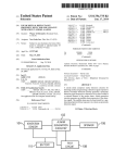
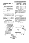
USOO8620841B1
(12) United States Patent
(10) Patent N0.:
Filson et a].
US 8,620,841 B1
(45) Date of Patent:
(54)
DYNAMIC DISTRIBUTED-SENSOR
THERMOSTAT NETWORK FOR
FORECASTING EXTERNAL EVENTS
(75)
Inventors: John B. Filson, Mounta1n V1eW, CA
_
_
5,240,178
5,348,078
5,381,950
5,395,042
_
A
A
A
A
8/1993
9/1994
1/ 1995
3/1995
5,476,221 A
12/1995
5,499,196 A
Dec. 31, 2013
Dewolfetal.
Dushane et al.
Aldndge
Riley et al.
Seymour
3/1996 Pacheco
(US); Eric B. Daniels, East Palo Alto,
CA (U S); Adam Mittleman, Redwood
CIIY’ C_A (Us); 516"“ L- Nelmes’
(commued)
FOREIGN PATENT DOCUMENTS
Rockhn, CA (U S); Yoky Matsuoka,
P2110 A110, CA (US)
CA
EP
(73) Assignee: Nest Labs, Inc., Palo Alto, CA (US)
(*)
Notice:
Subject to any disclaimer, the term of this
patent is extended or adjusted under 35
U'S'C' 15403) by 0 days'
Filed:
USPC
(Continued)
OTHER PUBLICATIONS
_
_
_
_
_
Primary Examiner * David Vlncent
(74) Attorney, Agent, or Firm *Kilpatrick Townsend &
StOthon’ LLP
(57)
ABSTRACT
(51)
(58)
2/2000
12/1991
(Continued)
Aug“ 31’ 2012
Int. Cl.
6an 15/18
(52) U-s- 0-
196069 B1
Yan et al. Research on event predictlon 1n t1me-ser1es data, 2004,
IEEE, pp. 2874-2878.*
(21) Appl. N0.: 13/601,890
(22)
2202008 C
(2006.01)
.......................................................... ..
706/12
Field of Classi?cation Search
_
_
Systems and methods for forecast1ng events can be prOV1ded.
USPC .................................................... .. 706/ 12, 45
A measurement database can Store sensor measurements’
S
each. having
been
provided by a non-portable electronic
.
.
.
It
ee app lea Ion
(56)
?lf
1t
e or comp e e seam
hh't.
ls Dry
References Cited
deV1ce W1th a pnmary purpose unrelated to collect1ng mea
surements from a type of sensor that collected the measure
ment. A measurement set identi?er can select a set of mea
’
U.S. PATENT DOCUMENTS
surements. The electronic devices associated With the set of
measurements can be in close geographical proximity relative
2
to their geographical proximity to other devices. An inter
’
IsgzaIka
evme
device correlator can access the set and collectively analyze
4,646,964 A
3/1987 Parker et a1.
4,656,835 A
4,657,179 A
4/1987 Kidder et al‘
4/ 1987 Aggers et al.
the measurements. An event detector can determlne Whether
an event occurred. An event forecaster can forecast a future
4,685,614 A
8/1937 LeYiIle
event property. An alert engine can identify one or more
2
439483040 A
Egéi?g 2211'
8/1990 Kobayashi et al‘
entities to be alerted of the future event property, generate at
least one alert identifying the future event property, and trans
m1t the at least one alert to the 1dent1?ed one or more ent1t1es.
5,()gg,645 A
2/1992 Bell
5,211,332 A
5/1993 Adams
5,224,648 A
7/1993 Simon et a1.
1°00 —\4
1012
_
18 Claims, 13 Drawing Sheets
107013
ROTA TE RING
|
US 8,620,841 B1
Page 2
(56)
References Cited
U_g_ PATENT DOCUMENTS
2003/0231001 A1
12/2003 Bruning
2004/0249479 A1
12/2004 Shorrock
2005/0043907 A1
2/2005 Eeke1e1n1.
2005/0128067 A1
6/2005 Zakrewsk1
9/2005 Breeden
9/2005 T655161 et al.
12/2005 Wlnlck
5,533,668 A
5,544,036 A
7/1996 Erikson
8/1996 Brown,Jr‘et 31‘
2005/0189429 A1
2005/0194456 A1
5555927 A
5,595,342 A
9/1996 Shah
1/1997 NICNair etal‘
2005/0270151 A1
2005/0280421 A1
5,611,484
5,635,896
5,644,173
5,646,349
5,761,083
3/1997
6/1997
7/1997
7/1997
6/1998
2006/0105697
2006/0149395
2006/0186214
2006/0196953
2006/0208099
A
A
A
A
A
5,802,467 A
Uhrich
Tinsleyet 31‘
Elliason et al‘
Twigg et al‘
Brownthetal,
9/1998 Salazar et 31‘
A1
A1
A1
A1
A1
2007/0052537 A1
5,839,654 A
11/1998 Weber
2007/0114295 A1
5,902,183
5,909,378
5,926,776
5,977,964
5/1999
6/1999
7/1999
11/1999
2007/0131787
2007/0228183
Zoos/0015740
2008/0015742
A
A
A
A
D’souza
De Milleville
Glorioso et a1.
Williams et a1.
A1
A1
Al
A1
6,062,482 A
5/2000 Gauthier et a1.
2008/0077474 A1
6,098,893
6,116,512
6,216,956
6,349,883
6,356,204
6,385,510
6,453,687
6,519,509
8/2000
9/2000
4/2001
2/2002
3/2002
5/2002
900‘”
200%
2008/0099568
2008/0128523
2008/0161977
2008/0185450
2008/0191045
2008/0317292
2009/0045263
2009/0171862
A
A
B1
B1
B1
B1
B2
B1
Berglund et a1.
Dushane etal.
Ehlersetal
Slmm9nsetal~
Gulndl
H°°g etal
$1.1m?“ etal
Nlethh etaL
6,548,967 B1*
4/2003 Dowllng etal. ............ .. 315/318
6,574,581 B1
6/2003 Bohreretal.
6604 023 B1
800% Brown et a1
6,619,555
B2
9/2003
6,622,925 B1
B2
6,645,066 B2
Rosen
‘
5/2006 Aronstarpet a1.
7/2006 Archack1etal.
8/2006 S1m0n etal.
9/2006 Slmon etal.
9/2006 Chapman etal.
3/2007 Stult_s et a1. ................. .. 340/540
5/2007 Jenk1ns
6/2007
10/2007
1/2008
1/2008
ROSSIGIBI.
Kennedyet a1.
Osann
Kulyk et a1.
3/2008 Dumas et a1. ................. .. 705/10
5/2008
6/2008
7/2008
8/2008
8/2008
12/2008
2/2009
7/2009
Nicodem etal.
Hoglundet a1.
Takach et a1.
Kwon etal.
Harter
Baker etal.
Mueller et al.
Harrodet a1
2009/0194601 A1
8/2009 H h
2009/0236433 A1
9/2009 Mueller et a1.
'
O r
2009/0243842
9/2003 Carner et a1.
11/2003 Gutta etal,
A1
A1
A1
A1
A1
A1
A1
A1
12/2005 Yomodaetal.
A1
10/2009
:1
2009/0261174 A1
M1tchell Ct {11.. . . . . . . . . . . . . . . . ..
umnc eta~
10/2009 Butler et a1.
6,769,482 B2
8/2004 Wagner et a1.
2010/0000239 A1
1/2010 Lifson et a1.
6,798,341 B1
6,851,621 B1
9/2004 Eckel et a1.
2/2005 Wackeretal.
2010/0006660 A1
2010/0019051 A1
1/2010 Leen et a1.
1/2010 Rosen
6,891,838 B1
6,909,921 B1
5/2005 Petite etal.
6/2005 Bllger
2010/0025483 A1
2010/0070084 A1
2/2010 Hoeyncketal.
3/2010 Steinberg etal.
6,975,958
6,983,889
6997
’
’ 390
7,024,336
B2
B2
B2
B2
7,055,759 B2
7,135,965 B2
7,156,316 B2
7,168,627 B2
7,360,370
RE40,437
7,434,742
7,460,690
7,469,550
7,537,171
7,558,648
7,571,865
7,605,714
7,644,869
B2
E
B2
B2
B2
B2
B2
B2
B2
B2
12/2005
V2006
2/2006
400%
6/2006
BohreretaL
A1168
Alles
531$me etal'
Wacker et a1.
11/2006 Chapman, Jr. et a1.
1/2007 Kates
1/2007 Kates
4/2008
7/2008
10/2008
12/2008
12/2008
5/2009
7/2009
8/2009
10/2009
1/2010
Shah et al‘
Rosen
Mnelleretal,
Cohen etal.
Chapman, Jr. et a1.
Mueller et a1.
Hoglund et a1.
Nicodem etal
Thompson etal~
Hoglund 9t 91-
2010/0070086
2010/0070234
2010/0084482
2010/0168924
2010/0211224
2010/0250009
2010/0261465
A1
A1
A1
A1
A1
A1
A1
3/2010
3/2010
4/2010
7/2010
8/2010
9/2010
10/2010
Harrodet a1.
Steinberg et a1.
Kenne dyet a 1 .
Tessier et a1
Keellng
et a1.'
.
Llfson et a1.
Rhoads et al.
2010/0262299
2010/0280667
2010/0289643
2010/0305771
2010/0308119
2010/0318227
2011/0001812
2011/0046792
2011/0046805
2011/0046806
A1
A1
A1
A1
A1
A1
A1
A1
A1
A1
10/2010
11/2010
11/2010
12/2010
12/2010
12/2010
1/2011
2/2011
2/2011
2/2011
Cheung
Steinberg
Trundle et a1.
Rodgers
Steinberg et a1.
Steinberg et a1.
Kang etal.
Imes et a1.
Bedros et a1.
Nagel et a1.
3138566153 5%
21/5818 glam?“ eialf
2011/0054699 A1
3/2011 Imes et a1.
13614976 S
7,784,704 B2
5/2010 Skafdmp etal'
8/2010 Hfmer
2011/0077896 A1
2011/0130636 A1
2011/0185895 A1
6/2011
,
,
ue
ere
a.
-
3/2011 Ste111berg
Danlel et a1.
8/2011 Freen
................ .. 600/301
7,802,618 B2
7,832,465 B2
9/2010 SlIIlOIl etal.
11,2010 Zou etal‘
7,837,128 B2
11/2010 Heltetal‘
7,847,681 B2
12/2010 Singhal et al‘
2012/0065935 A1
3/2012 Stelnberg et a1.
7,848,900 B2
12/2010 Steinberg etal.
2012/0085831 A1
4/2012 KOPP
7,854,389 B2
7,904,209 B2
12/2010 Ahmed
3/2011 Podgornyetal.
2012/0158350 A1
2012/0221151 A1
6/2012 Ste1nberg
8/2012 Steinberg
7,904,830 B2
3/2011 Hoglundetal.
8,010,237 B2
8/2011 Cheung
8,019,567 132
9;2011 Steinlgefg
8,090,477 B1
8,131,497 B2
8,180,492 B2
8,195,313 B1*
2001/0033481 A1*
12012 Stein erg
3/2012 Steinberg
5/2012 Steinberg
6/2012 Fadell et a1. .................. .. 700/83
10/2001 Chien ........................... .. 362/34
2011/0253796 A1
10/2011 Posaetal.
2011/0307103 A1
12/2011 Cheung
2012/0262303 A1*
10/2012 Fahey .................... .. 340/870.02
FOREIGN PATENT DOCUMENTS
EP
JP
1275037 B1
59106311 A
2/2006
6/1984
JP
JP
01252850 A
09298780 A
10/1989
11/1997
US 8,620,841 B1
Page 3
(56)
References Cited
Author Unknown, Trane XL950 Installation Guide, Trane, 2011, 20
pages.
FOREIGN PATENT DOCUMENTS
Author Unknown, Venstar T2900Manual, Venstar, Inc., 2008, 113
pages.
JP
WO
10023565 A
2008054938 A2
1/1998
5/2008
OTHER PUBLICATIONS
Zhang et al., Forecasting with arti?cial neural networks: The state of
the art, 1998, Elsevier, pp. 1-28.*
Author Unknown, Aprilaire Electronic Thermostats Model 8355
User’s Manual, Research Products Corporation, 2000, 16 pages.
Author Unknown, Braeburn 5300 Installer Guide, Braeburn Sys
tems, LLC, 2009, 10 pages.
Author Unknown, Braeburn Model 5200, Braeburn Systems, LLC,
2011, 11 pages.
Author Unknown, Ecobee Smart Si Thermostat Installation Manual,
Ecobee, 2012, 40 pages.
Author Unknown, Ecobee Smart Si Thermostat User Manual,
Ecobee, 2012, 44 pages.
Author Unknown, Ecobee Smart Thermostat Installation Manual,
2011,20 pages.
Author Unknown, Ecobee Smart Thermostat User Manual, 2010, 20
pages.
Author Unknown, VisionPRO TH8000 Series Installation Guide,
Honeywell International, Inc., 2012, 12 pages.
Author Unknown, VisionPRO TH8000 Series Operating Manual,
Honeywell International, Inc., 2012, 96 pages.
Author Unknown, VisionPRO Wi-Fi Programmable Thermostat,
Honeywell International, Inc., 2012, 48 pages.
Allen et al., Real-Time Earthquake Detection and Hazard Assess
ment by ElarmS Across California, Geophysical Research Letters,
vol. 36, LO0B08, 2009, pp. 1-6.
Arens et al., Demand Response Enabling Technology Development,
Phase I Report: Jun. 2003-Nov. 2005, Jul. 27, P:/DemandRes/UC
Papers/DR-PhaselReport-Final Draft Apr. 24-26.doc, University of
California Berkeley, pp. 1-108.
Arens et al., New Thermostat Demand Response Enabling Technol
ogy, Poster, University of California Berkeley, Jun. 10, 2004.
Bourke, Server Load Balancing, O’Reilly & Associates, Inc., Aug.
2001, 182 pages.
Deleeuw, Ecobee WiFi Enabled Smart Thermostat Part 2: The Fea
tures
Review,
Retrieved
from
<URL:
http://www.
homenetworkenabled.com/content.php?136-ecobee-WiFi-enabled
Author Unknown, Electric Heat Lock Out on Heat Pumps, Washing
Smart-Thermostat-Part-2-The-Features-review>, Dec. 2, 2011, 5
ton State University Extension Energy Program, Apr. 2010, pp. 1-3.
Author Unknown, Honeywell Installation Guide FocusPRO TH6000
Series, Honeywell International, Inc., 2012, 24 pages.
Author Unknown, Honeywell Operating Manual FocusPRO TH6000
Series, Honeywell International, Inc., 2011, 80 pages.
pages.
Author Unknown, Honeywell Prestige IAQ Product Data, Honeywell
International, Inc., 2012, 126 pages.
Author Unknown, Honeywell Prestige THX9321-9421 Operating
Manual, Honeywell International, Inc., 2011, 120 pages.
Author Unknown, Hunter Internet Thermostat Installation Guide,
Hunter Fan Co., 2012, 8 pages.
Author Unknown, Lennox ComfortSense 5000 Owners Guide, Len
nox Industries, Inc., 2007, 32 pages.
Author Unknown, Lennox ComfortSense 7000 Owners Guide, Len
nox Industries, Inc., 2009, 15 pages.
Author Unknown, Lennox iComfort Manual, Lennox Industries,
Inc., 2010, 20 pages.
Author Unknown, NetX RP32-WiFi Network Thermostat Speci?ca
tion Sheet, Network Thermostat, 2012, 2 pages.
Author Unknown, RobertShaw Product Manual 9620, Maple Chase
Company, 2001, 14 pages.
Gao et al., The Self-Programming Thermostat: Optimizing Setback
Schedules Based on Home Occupancy Patterns, in Proceedings of the
First ACM Workshop on Embedded Sensing Systems for Energy
Ef?ciency in Buildings, Nov. 3, 2009, 6 pages.
Loisos et al., Buildings End-Use Energy Ef?ciency: Alternatives to
Compressor Cooling, California Energy Commission, Public Interest
Energy Research, Jan. 2000, 80 pages.
Lu et al., The Smart Thermostat: Using Occupancy Sensors to Save
Energy in Homes, in Proceedings of the 8th ACM Conference on
Embedded Networked Sensor Systems, Nov. 3-5, 2010, pp. 211-224.
Mozer, The Neural Network House: An Environmental that Adapts to
it’s Inhabitants, AAAI Technical Report SS-98-02, 1998, pp. 110
1 14.
International Search Report and Written Opinion mailed Nov. 2,
2012 in Application No. PCT/US2012/053502 ?led Aug. 31, 2012.
Sakaki et al., Earthquake Shakes Twitter Users: Real-time Event
Detection by Social Sensors, in Proceedings of the Nineteenth Inter
national WWW Conference, Apr. 26-30, 2010, 10 pages.
White et al., A Conceptual Model for Simulation Load Balancing,
Proc. 1998 Spring Simulation Interoperability Workshop, 1998, 7
Author Unknown, RobertShaw Product Manual 9825i2, Maple
Chase Company, 2006, 36 pages.
Author Unknown, SYSTXCCUIZOl-V In?nity Control Installation
Instructions, Carrier Corp, 2012, 20 pages.
Author Unknown, T8611G Chronotherm IB Deluxe Programmable
Heat Pump Thermostat Product Data, Honeywell International Inc.,
pages.
Honeywell Prestige THX9321 and TXH9421 Product Data 68/0311,
Honeywell International, Inc., Jan. 2012, 126 pages.
Introducing the New Smart Si Thermostat, Datasheet [online].
Ecobee, Mar. 2012 [retrieved on Feb. 25, 2013]. Retrieved from the
Internet: <URL: https://www.ecobee.com/solutions/home/smart-si/
1997, 24 pages.
>.
Author Unknown, TB-PAC, TB-PHP, Base Series Programmable
Thermostats, Carrier Corp., 2012, 8 pages.
pages.
Author Unknown, The Perfect Climate Comfort Center PC8900A
NetX RP32-Wi? Network Thermostat Consumer Brochure, Network
W8900A-C Product Data Sheet, Honeywell International Inc, 2001,
Thermostat, May 2011, 2 pages.
Venstar T5800 Manual, Venstar, Inc., Sep. 2011, 63 pages.
White Rodgers (Emerson) Model 1F81-261 Installation and Operat
44 pages.
Author Unknown, Trane Communicating Thermostats for Fan Coil,
Trane, 2011,32 pages.
Author Unknown, Trane Communicating Thermostats for Heat
Pump Control, Trane, 2011, 32 pages.
Author Unknown, Trane Install XL600 Installation Manual, Trane,
2006, 16 pages.
Lux PSPU732T Manual, LUX Products Corporation, Jan. 2009, 48
ing Instructions, White Rodgers, Apr. 2010, 8 pages.
White Rodgers (Emerson) Model IF98EZ-1621 Homeowner’s User
Guide, White Rodgers, Jan. 2012, 28 pages.
* cited by examiner
US. Patent
Dec. 31, 2013
Sheet 1 0113
US 8,620,841 B1
DEVICE
1 00
REPLA CEABLE
/'
114
MODULE
~,
x' 104
'v’
102
R
I
\x
‘s
USER
‘~
INTERFACE
'
,'
.
110
I|
:
i |
R
DOCKING
2 I
:
COMPONENT
.
STAT/ON
z
COMMUNICATIONS
,
I
POWER
E I
CONNECT/ON
E |_
—
I Z
I a‘
__|/_/_ 106
;
.
l
'
u
,
‘
—-
—
-—
| 1
:
...................... .
‘
\
\
\‘
116
\\
108
R
~
I
COMPONENTS
FIG. 1
"
US. Patent
Dec. 31, 2013
US 8,620,841 B1
Sheet 2 0f 13
wow
wQDOmQzR
mmw
ENFF
/\/
va
mom
/
mum2w
/ \/
US. Patent
Dec. 31, 2013
Sheet 3 0f 13
US 8,620,841 B1
NEST/PARTNER(S)
A 308
CHARITIES
$322
GOVERNMENTS
$324
DA TA
ENGINES:
_- STATISTICS
T A306
-- INFERENCES
-- INDEXING
_
ACADEMIC
;
INSTITUTIONS
$325
BUSINESSES
~/-\328
UTILITIES
$330
2
U
I
I
NEST
~/\264
A
V
OPS DA TA
\
V
SERVICES
\
\
302
\304
262
INTERNET
&
ES
EHUB:
US. Patent
Dec. 31, 2013
Sheet 4 0f 13
US 8,620,841 B1
EX:
EXTRINSIC INFORMATION
-- WEATHER FORECAST
. ., FROM INTERNE
416 f
(e g
"PRICES
n
-- NEIGHBORHOOD/HOME INFORMATION
PROCESSING
PARADIGMS
A
,_
1
E)‘.
MANAGED
--
ECURITY
-- DEMAND/
SERVICES
\RESPONSE
410a
ADVERTISING/
COMMUN/CA TION
PROCESSING
ENGINE
306 <
\4101)
SOCIAL
\4100
CHALLENGES/
RULES/
COMPLIANCE/
REWARDS
\
\_
410d
Y
A
A
A
A
V
V
V
08 SS
05; SS
DS SS
DC,SC
Ocisc
DC SC
:
:
404
k
DS = DATA SOURCE
DC = DATA CONSUMER
88 = SERVICE SOURCE
SC = SERVICE CONSUMER
V
. .
\ 08 SS f
408
DC,SC \
402 _/‘
:
Y
406
I
DE V125
-— LIGHTS. HVAC, WATER CONTROLLERS/SENSORS
-- HOME APPLIANCES
—- SMOKE/CO/HAZARD SENSORS/ALARMS
FIG. 4
US. Patent
Dec. 31, 2013
Sheet 5 0f 13
US 8,620,841 B1
EX:
-- WEA THER FORECAST
EXTRINSI C INFORMATION
(e.g., FROM INTERNET)
" PRICES
-- NEIGHBORHOOD/HOME INFORMA TION
306
L\
PROCESSING ENGINE
502
5 75
----------------------------------------------------------- --
505
POINTS
DATA
PROF/LES
USER
508
>>>>>>>>>>>> ~
\__\
510
WEIGHT/
ADJUSTMENT
ASSIGNER
~~~~
‘ R
V
i 777 A
\W
INTER—DEVICE
CORRELATOR
z“,
I
516
V
Y
ALERTENG'NE
A
A
504
512
i
514
DATA SET
"" ">
LOCA
DEVICE
TIONS
IDENTIFIER
‘
EVENT
"
EVENT DETECTOR
'
FORECASTER
A
A
A
A
A
v
v
v
v
os‘ss
08:88
05:35
DC_ so
00% so
00% so
\
08 = DA TA SOURCE
.
. .
05.35
no so
J
Y
DEV/CE
DC = DA TA CONSUMER
EX
SS : SERVICE SOURCE
--
SC : SERVICE CONSUMER
-- SMOKE/CO/HAZARD SENSORS/ALARMS
FIG. 5
gig/LAACNEVQJER CONTROLLERS/SENSORS
US. Patent
Dec. 31, 2013
Sheet 6 0f 13
US 8,620,841 B1
600a
START
605
DETECT SENSOR
MEASUREMENT
3
610
NO
TRANSMISSION
CRITERION
“““““““““ “
‘
1
v
SA TISFIED?
620
PAUSE UNTIL NEXT
MEASUREMENT TIME
I
f
4
FIG. 6A
TRANSMI T
SENSOR DA TA
615
US. Patent
Dec. 31, 2013
Sheet 7 of 13
US 8,620,841 B1
600b
START
605
I
DETECT SENSOR
MEASUREMENT
I
i
1
6
f
615
TRANSMI T SENSOR DA TA
+
PAUSE UNTIL NEXT
MEASUREMENT TIME
FIG. 65
620
f
US. Patent
Dec. 31, 2013
Sheet 8 0f 13
US 8,620,841 B1
700
w/
705
I
ACCESS PLURALITY OF SENSOR DA TA POINTS
I
I
ASSOC/A TE EACH SENSOR DATA
POINT WITH TIME AND LOCATION
710
715
I
f
IDENTIFY SET OF SENSOR DA TA POINTS
720
II
f
ANALYZE SET OF SENSOR DATA POINTS
725
v
f
DETECT EVENT OCCURRENCE, LOCATION,
MAGNITUDE AND/OR TRAJECTORY
730
\I
f
FORECAST FUTURE PROPERTIES OF EVENT
735
II
I
IDENTIFY ENTITIES TO BE ALERTED
740
\I
GENERA TE AND SEND ALERTS
FIG. 7
I
US. Patent
Dec. 31, 2013
Sheet 9 0f 13
US 8,620,841 B1
800
805
APPLY WEIGHT TO EACH SENSOR DA TA POINT
I
v
810
I
APPLYADJUSTMENTS TO ONE
OR MORE SENSOR DA TA POINTS
f815
FIT SENSOR DATA POINTS
820
v
f
ASSESS EVENT-OCCURRENCE CRITERIQN
825
v
I
ES TIMA TE EVENT LOCA TION, MA GNITUDE AND/OR
TRAJEC TORY BASED ON FIT PARAMETERS
FIG. 8
US. Patent
Dec. 31, 2013
Sheet 10 0f 13
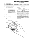
US 8,620,841 B1
p/
905
I
EST/MA TE EVENT TRAJEC TORY BASED ON
EVENT MAGNITUDE OR PAST TRAJECTORY
910
I
I
FORECAST FUTURE EVENT LOCA TION
BASED ON ESTIMATED EVENT TRAJECTORY
1a
v
915
f
IDENTIFY DEVICES IN
FORE CAS TED FUTURE EVENT LOCA TION
i
TRANSMITALERT TO IDENTIFIED
DEVICES OR TO USER DEVICES
ASSOCIATED WITH IDENTIFIED DEVICES
FIG. 9
f
920
900
US. Patent
Dec. 31, 2013
“mom 10708
Sheet 11 0113
US 8,620,841 B1
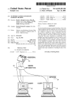
ROTA TE RING
1012
1000——\
FIG. 108
1012
PRESS
IN WARD
US. Patent
Dec. 31, 2013
Sheet 12 0113
US 8,620,841 B1
1100
A a8
r1102
-
\1
II
>
1112
-
FIG. 11
[Z]
US. Patent
Dec. 31, 2013
US 8,620,841 B1
Sheet 13 0f 13
mow”.
E6mg2o5i.w1n
5“:2m6:wa Nu6w:26:wa 9%6w:26:wa
59:0 wmuSQ
omEBw $2.5
Eoncm wmo< Eo mE
mo;
H
Sac.
vamoSwQ
63:2
Awro i
cow?
H
cozmuE
)fJO/VUBN uogleogunwwog
mam?
f
Q
r
i
I
GE
F
w
I
motBE
omw
0mm
w
US 8,620,841 B1
1
2
DYNAMIC DISTRIBUTED-SENSOR
THERMOSTAT NETWORK FOR
FORECASTING EXTERNAL EVENTS
network of devices can include smart devices across multiple
rooms, across multiple buildings, across cities, etc. Within a
given network, the devices can include different device types
or same or similar device types. Each device within the net
FIELD
work can include one or more sensors (e.g., to detect motion
This patent speci?cation relates to systems, methods, and
related computer program products for aggregating measure
humidity, or pressure). Data indicative of the sensor measure
of the sensor, motion of an external object, temperature,
ments can be conditionally transmitted (e.g., upon detection
of an abnormal event) or regularly transmitted by a respective
ments obtained from a dynamic network of sensors in order to
forecast external events. More particularly, this patent speci
device to a central server. The central server can correlate the
?cation relates to a dynamic process of identifying a set of
data across a set of devices in order to estimate whether
readings are due to a sensor malfunction, a stationary event,
sensors (e.g., each being housed within a thermostat) appli
or a moving event. For example, accelerometer readings from
a set of devices within a locality (e.g., within a Zip code) can
be used to estimate whether an earthquake is occurring, tem
perature readings from a set of devices within a locality (e. g.,
within a city) can be used to estimate weather patterns, and
motion-detection readings from a set of devices within a
locality (within a set of rooms) can be used to estimate a
cable to an event’s forecast, aggregating measurements from
the set of sensors, and forecasting a future characteristic of the
event based on the aggregated measurements.
BACKGROUND
Accurate and timely prediction of impending future events
can be useful and bene?cial in many ways. For example,
predicting where and when severe weather events will strike
can provide residents with the warning necessary to protect
20
and/or strength), and can send alerts to other devices within a
region predicted to be affected. The other devices can then
themselves and their belongings from the damage. As another
example, timely prediction of impending earthquake events,
even if provided only a few seconds in advance, can prevent
trajectory of a person within a building. The central server can
then predict characteristics of a future event (e.g., its location
alert users of the event or can automatically implement device
25
settings to prepare for the event.
injury or death by allowing recipients of earthquake alarm to
According to one or more preferred embodiments directed
move quickly to a safer location or position before the onset
particularly to earthquake detection and prediction, it has
of the earthquake. Even predictions dealing with less severe
been found particularly advantageous to embed one or more
accelerometers or similar movement sensors within one or
events can result in substantial advantages. For example, if a
person’s actions can be reliably predicted, other related
people can more ef?ciently plan their activities and/or par
ticular conveniences can be appropriately timed to be ready
30
stationary dispositions within the home. It has been found that
upon the person’s arrival at a location. Utilization of such
advantages could improve productivity, safety, and comfort
on many different scales and in many different ways.
35
network-connected thermostats and network-connected haZ
ard detectors are two particularly useful smart-home devices
within which to embed such sensors, although many other
examples (network-connected light switches, network-con
Despite these strong advantages, producing reliable pre
nected doorbells, network-connected home appliances) are
also within the scope of the present teachings. According to a
dictions remains a dif?cult task. There are many unknowns
that in?uence a future event, and frequently, contributing
variables are also unknown. Thus, weather predictions are
frequently erroneous, natural disasters frequently strike with
more network-connected smart-home devices that are each
af?xed to a home structure or that otherwise have normally
40
preferred embodiment, the smart-home, accelerometer
equipped (or other motion-sensing-equipped) devices within
out warning, and substantial time is wasted waiting on certain
any particular local geographic area (such as a ZIP code) are
events, such as the arrival of others, or preparing an environ
pro grammed and con?gured to quickly report the occurrence
ment only after such others actually arrive.
of their individual sensed movements to a common central
server, such as a cloud-based server system, which is, in turn,
SUMMARY
45
is programmed and con?gured to perform correlation calcu
lations on the received data to detect the occurrence of an
earthquake event and, where applicable, promptly detect a
geographical speed and trajectory of the earthquake event.
Provided according to one or more embodiments are sys
tems, methods, computer program products, and related busi
ness methods for utiliZing measurements obtained from a set
of distributed sensors to predict events. Each sensor within a
network of sensors can collect data and transmit the data to a
central server. The central server can identify the set of sen
sors from the network of sensors by, e.g., identifying sensors
within a geographical region, identifying sensors that trans
mitted data within a time period and/or identifying sensors
that transmitted a particular type of data. The central server
Alarms or other advance warnings can then be promptly
50
of the earthquake event or to ?rst responders. In one particu
larly advantageous embodiment, the same smart-home
devices within which the accelerometers/movement sensors
are embedded are also equipped to receive these warnings and
55
can then aggregate data across the set of sensors, estimate
characteristics of a current event (e.g., its existence, severity,
or movement), and predict characteristics of the event in the
future. The central server can then transmit information about
the predicted characteristic to one or more devices associated
communicated to persons geographically located in the path
to quickly provide audible and/or visual earthquake alarms to
home occupants. Even if provided only seconds before the
earthquake arrival, a valuable service is provided because
these seconds can be used by the occupant to move to a safer
location or position.
60
Especially for scenarios in which the network-connected
smart-home devices (such as network-connected thermo
(e. g., smoke detector and/or carbon-monoxide detector), light
stats, network-connected hazard detectors, etc.) constitute
even modestly popular consumer items, there is thereby func
tionally formed a “crowdsourced” earthquake detection net
work that can be orders of magnitude larger than known
o?icial earthquake detection networks in terms of the number
switch, wall-plug interface, security system, or appliance. A
of accelerometer/movement sensor nodes provided. More
with users likely to be affected by or interested in the future
event.
As a speci?c example, a building can include one or more
smart devices, such as a thermostat, hazard-detection unit
65
US 8,620,841 B1
3
4
over, by virtue of correlations that can be performed for
localized neighborhoods or geographies, the crowdsourced
ing the future event property, and can transmit the at least one
earthquake detection network can be highly robust against
In some embodiments, a method for forecasting events is
provided. A plurality of sensor measurements in a measure
ment database can be stored, each sensor measurement hav
alert to the identi?ed one or more entities.
false alarms. Thus, for example, while one house in a neigh
borhood might be shaking due to romping teenagers or a
nearby passing truck, which might trigger a sensed earth
ing been provided by a mounted electronic device. A primary
quake detection event when considered in isolation, the fact
that other homes in the community are not shaking will be
factored in by the correlations performed by the central server
and the false-alarm condition will be avoided.
It is to be appreciated that, while crowdsourced earthquake
purpose of at least one respective electronic device can be not
related to collecting measurements from a type of sensor that
collected the sensor measurement. A set of sensor measure
ments from the plurality of sensor measurements in the mea
surement database can be selected. The electronic devices
associated with the set of sensor measurements can be in close
detection based on a population of accelerometer-equipped,
network-connected smart-home devices represents one par
geographical proximity relative to their geographical prox
ticularly useful and advantageous embodiment, the scope of
imity to other devices. The sensor measurements can be col
the present teachings is applicable across a broad variety of
scenarios, including those discussed further herein, in which
lectively analyzed to determine whether a large-scale event
a population of smart-home devices is provided that are each
was occurring. The determination that a large-scale event was
equipped with one or more sensors, and the outputs of those
sensors are received and processed in a groupwise manner to
achieve one or more useful “crowdsourced” intelligence
results. Not unimportantly, according to one or more of the
occurring can require consistency between at least two of the
20
a same or different collective analysis of the sensor measure
ments. One or more entities to be alerted of the future event
preferred embodiments, the relative ubiquity of the sensor
network that is key to the effective crowdsourced intelligence
is fostered primarily by the popularity, attractiveness, and/or
essential underlying functionality of the smart-home devices
sensor measurements. A future event property can be fore
casted. The future event property can be forecasted based on
property can be identi?ed. At least one alert identifying the
future event property can be generated, and the at least one
25 alert can be transmitted to the identi?ed one or more entities.
within which the sensors are embedded, rather than their
In some embodiments, a crowdsourced event detection
functionality as part of the crowdsourced detection network.
For example, for the particular exemplary scenario of a
network is provided that includes a population of non-por
smart-home device comprising an elegant, visually appeal
table smart-home devices. Each smart-home device can have
a primary function as one of a thermostat, a hazard detector,
a wall switch, an entertainment device, a lighting device, and
a home appliance. Each smart-home device can include a
ing, intelligent, network-connected, self-programming ther
housing and at least one sensor coupled to the housing. The at
crowdsourced earthquake detection network, the accelerom
eters/movement sensors may be preferably embedded in a
30
mostat such as that described in the commonly assigned
least one sensor can be con?gured to sense at least one envi
USO8195313B1, which is hereby incorporated by reference
ronmental characteristic or condition that is generally unre
in its entirety for all purposes. Notably, the popularity and
increasing ubiquity of the smart-home device of
USO8195313B1 is driven by its consumer appeal, along with
35
smart-home device can further include a data transmission
component con?gured to transmit ?rst information represen
the fact that every home usually needs at least one thermostat.
tative of said least one sensed environmental characteristic or
While being a greatly bene?cial by-product of the
device’subiquity when adapted and con?gured according to
the present teachings, the fact that the device can be made part
of a life-saving crowdsourced earthquake detection network
according to the present teachings need not itself be the cen
tral reason for that ubiquity.
In some embodiments, an event-forecasting system is pro
lated to the primary function of the smart-home device. Each
40
condition for reception by an aggregating processor. The
aggregating processor can be con?gured and programmed to
receive the ?rst information from each of a plurality of the
smart-home devices and to forecast a future event based on a
collective analysis thereof. The aggregating processor can be
45
further con?gured and programmed to identify one or more
entities to be alerted of the forecasted future event and to
vided. A measurement database can store a plurality of sensor
transmit second information representative of the forecasted
measurements, each sensor measurement having been pro
future event to the identi?ed one or more entities.
vided by a non-portable electronic device. A primary purpose
of each respective electronic device can be unrelated to col
lecting measurements from a type of sensor that collected the
BRIEF DESCRIPTION OF THE DRAWINGS
50
The inventive body of work will be readily understood by
referring to the following detailed description in conjunction
with the accompanying drawings, in which:
sensor measurement. A measurement set identi?er can select
a set of sensor measurements from the plurality of sensor
measurements in the measurement database. The electronic
devices associated with the set of sensor measurements canbe
in close geographical proximity relative to their geographical
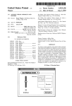
FIG. 1 illustrates an example of general device components
55
which can be included in an intelligent, network-connected
proximity to other devices. An inter-device correlator can
device;
access the selected set of sensor measurements and collec
FIG. 2 illustrates an example of a smart home environment
within which one or more of the devices, methods, systems,
tively analyze the sensor measurements. An event detector
services, and/or computer program products described fur
can determine whether an event has occurred based on the
results of the collective analysis. The determination that an
event has occurred can require that a criterion involving at
60
FIG. 3 illustrates a network-level view of an extensible
devices and services platform with which a smart home envi
ronment can be integrated;
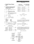
FIG. 4 illustrates an abstracted functional view of the
least two of the sensor measurements be satis?ed. An event
forecaster can forecast a future event property. The future
event property can be forecasted based on a same or different
collective analysis of the sensor measurements. An alert
engine can identify one or more entities to be alerted of the
future event property, can generate at least one alert identify
ther herein can be applicable;
65
extensible devices and services platform of FIG. 3;
FIG. 5 illustrates components of processing engine accord
ing to an embodiment of the invention;
US 8,620,841 B1
6
5
FIGS. 6A and 6B illustrate ?owcharts for processes 60011
the scope of applicability of the described extensible devices
of transmitting data from a device 100 to a remote server in
and services platform is not so limited.
As described further herein, one or more intelligent, multi
sensing, network-connected devices can be used to promote
user comfort, convenience, safety and/ or cost savings. FIG. 1
accordance with an embodiment of the invention;
FIG. 7 illustrates a ?owchart for a process of analyzing
sensor data points to forecast event properties;
FIG. 8 illustrates a ?owchart for a process of analyzing
sensor data points to detect event properties;
FIG. 9 illustrates a ?owchart for a process of forecasting
illustrates an example of general device components which
can be included in an intelligent, network-connected device
100 (i.e., “device”). Each of one, more or all devices 100
event properties and sending alerts;
within a system of devices can include one or more sensors
FIGS. 10A-10B illustrate an example of a thermostat
device that may be used to collect sensor measurements;
FIG. 11 illustrates a block diagram of an embodiment of a
102, a user-interface component 104, a power supply (e.g.,
including a power connection 106 and/or battery 108), a
communications component 110, a modularity unit (e.g.,
including a docking station 112 and replaceable module 114)
and intelligence components 116. Particular sensors 102,
computer system; and
FIG. 12 illustrates a block diagram of an embodiment of a
special-purpose computer.
user-interface components 104, power-supply con?gura
tions, communications components 110, modularity units
DETAILED DESCRIPTION OF THE INVENTION
and/or intelligence components 116 can be the same or simi
lar across devices 100 or can vary depending on device type or
Provided according to one or more embodiments are sys
tems, methods, computer program products, and related busi
20
ness methods for utiliZing measurements obtained from a set
of distributed sensors to predict events. Each sensor within a
network of sensors can collect data and transmit the data to a
central server. As used herein, central server refers to any of a
variety of different processing devices and/or groups of pro
cessing devices that are capable of receiving data derived
more sensors 102 in a device 100 may be able to, e.g., detect
25
from the sensors and processing the received information. As
acceleration, temperature, humidity, water, supplied power,
proximity, external motion, device motion, sound signals,
ultrasound signals, light signals, ?re, smoke, carbon monox
ide, global-positioning-satellite (GPS) signals, or radio-fre
quency (RF) or other electromagnetic signals or ?elds. Thus,
for example, sensors 102 can include temperature sensor(s),
would be readily appreciated by the skilled artisan, it is not
humidity sensor(s), hazard-related sensor(s) or other environ
required that the one or more processors forming the central
server be located in any particular geographical location rela
model.
By way of example and not by way of limitation, one or
30
mental sensor(s), accelerometer(s), microphone(s), optical
tive to the sensors or to each other. While in one embodiment
sensors up to and including camera(s) (e. g., charged-coupled
the central server can be implemented in cloud-based com
device or video cameras), active or passive radiation sensors,
puting and storage environment such as the EC2 (Elastic
GPS receiver(s) or radio-frequency identi?cation detector(s).
Compute Cloud) offering from Amazon.com of Seattle,
Wash., it is to be appreciated that the central server can be
implemented on any of a variety of different hardware and
35
software platforms, ranging from concentrated single-loca
tion computing devices to distributed networks of computing
devices, including virtualized computing devices. The central
server can identify the set of sensors from the network of
40
sensors by, e.g., identifying sensors within a geographical
region, identifying sensors that have transmitted data within a
time period and/ or identifying sensors that have transmitted a
particular type of data. The central server can then aggregate
for energy-ef?ciency objectives or smart-operation objec
data across the set of sensors, estimate characteristics of a 45
One or more user-interface components 104 in device 100
may be con?gured to present information to a user via a visual
display (e.g., a thin-?lm-transistor display or organic light
emitting-diode display) and/or an audio speaker. User-inter
server can then transmit information about the predicted char
acteristic to one or more devices associated with users likely
50
face component 104 can also include one or more user-input
components to receive information from a user, such as a
touchscreen, buttons, scroll component (e.g., a movable or
virtual ring component), microphone or camera (e.g., to
detect gestures). In one embodiment, user-input component
104 includes a click-and-rotate annular ring component,
tive examples of devices, methods, systems, services, and/or
computer program products that can be used in conjunction
with an extensible devices and services platform that, while
being particularly applicable and advantageous in the smart
smoke detector). The secondary sensor(s) can sense other
types of data (e. g., motion, light or sound), which can be used
tives. In some instances, an average user may even be
unaware of an existence of a secondary sensor.
current event (e.g., its existence, severity, or movement), and
predict characteristics of the event in the future. The central
to be affected by or interested in the future event.
Embodiments described further herein are but representa
While FIG. 1 illustrates an embodiment with a single sensor,
many embodiments will include multiple sensors. In some
instances, device 100 includes one or more primary sensors
and one or more secondary sensors. The primary sensor(s)
can sense data central to the core operation of the device (e. g.,
sensing a temperature in a thermostat or sensing smoke in a
55
wherein a user can interact with the component by rotating the
ring (e.g., to adjust a setting) and/or by clicking the ring
home context, is generally applicable to any type of enclosure
or group of enclosures (e.g., of?ces, factories or retail stores),
inwards (e.g., to select an adjusted setting or to select an
vessels (e.g., automobiles or aircraft), or other resource-con
option). In another embodiment, user-input component 104
suming physical systems that will be occupied by humans or
with which humans will physically or logically interact. It
will be appreciated that devices referred to herein need not be
includes a camera, such that gestures can be detected (e.g., to
60
changed).
A power-supply component in device 100 may include a
power connection 106 and/or local battery 108. For example,
within an enclosure or vessel. For example, a device canbe on
an exterior surface, nearby or connected to an enclosure or
vessel. As another example, a device can include a portable
device, such as a cell phone or laptop, that is con?gured to be
carried by a user. Thus, although particular examples are set
forth in the context of a smart home, it is to be appreciated that
indicate that a power or alarm state of a device is to be
65
power connection 106 can connect device 100 to a power
source such as a line voltage source. In some instances, con
nection 106 to an AC power source can be used to repeatedly
charge a (e.g., rechargeable) local battery 108, such that bat
US 8,620,841 B1
7
8
tery 108 can later be used to supply power if needed in the
purpose processors or application- speci?c integrated circuits,
event of an AC power disconnection or other power de?
combinations thereof, and/ or using other types of hardware/
ciency scenario.
?rmware/ software processing platforms. The intelligence
A communications component 110 in device 100 can
include a component that enables device 100 to communicate
components 116 can furthermore be implemented as local
ized versions or counterparts of algorithms carried out or
with a central server or a remote device, such as another
governed remotely by central servers or cloud-based systems,
such as by virtue of running a Java virtual machine (JVM) that
device described herein or a portable user device. Communi
cations component 110 can allow device 100 to communicate
executes instructions provided from a cloud server using
Asynchronous Javascript and XML (AJAX) or similar proto
cols. By way of example, intelligence components 116 can be
via, e.g., Wi-Fi, ZigBee, 3G/4G wireless, CAT6 wired Ether
net, HomePlug or other powerline communications method,
telephone, or optical ?ber, by way of non-limiting examples.
intelligence components 116 con?gured to detect when a
location (e.g., a house or room) is occupied, up to and includ
Communications component 110 can include a wireless card,
an Ethernet plug, or nother transceiver connection.
A modularity unit in device 100 can include a static physi
ing whether it is occupied by a speci?c person or is occupied
by a speci?c number of people (e.g., relative to one or more
cal connection, and a replaceable module 114. Thus, the
thresholds). Such detection can occur, e.g., by analyZing
microphone signals, detecting user movements (e.g., in front
of a device), detecting openings and closings of doors or
garage doors, detecting wireless signals, detecting an IP
modularity unit can provide the capability to upgrade replace
able module 114 without completely reinstalling device 100
(e. g., to preserve wiring). The static physical connection can
include a docking station 112 (which may also be termed an
interface box) that can attach to a building structure. For
example, docking station 112 could be mounted to a wall via
screws or stuck onto a ceiling via adhesive. Docking station
112 can, in some instances, extend through part of the build
ing structure. For example, docking station 112 can connect
to wiring (e.g., to 120V line voltage wires) behind the wall via
20
116 may include image-recognition technology to identify
particular occupants or objects.
In some instances, intelligence components 116 can be
25
a hole made through a wall’s sheetrock. Docking station 112
can include circuitry such as power-connection circuitry 106
and/ or AC-to-DC powering circuitry and can prevent the user
home preferences or user-speci?c preferences). As another
30
such that, e. g., a thermostat device includes a different dock
ing station than a smoke detector device. In some instances,
docking stations 112 can be shared across multiple types
and/or models of devices 100.
Replaceable module 114 of the modularity unit can include
con?gured to predict desirable settings and/ or to implement
those settings. For example, based on the presence detection,
intelligence components 116 can adjust device settings to,
e.g., conserve power when nobody is home or in a particular
room or to accord with user preferences (e.g., general at
from being exposed to high-voltage wires. In some instances,
docking stations 112 are speci?c to a type or model of device,
address of a received signal, or detecting operation of one or
more devices within a time window. Intelligence components
example, based on the detection of a particularperson, animal
or object (e.g., a child, pet or lost object), intelligence com
ponents 116 can initiate an audio or visual indicator of where
the person, animal or object is or can initiate an alarm or
some or all sensors 102, processors, user-interface compo
security feature if an unrecognized person is detected under
certain conditions (e.g., at night or when lights are out).As yet
another example, intelligence components 116 can detect
nents 104, batteries 108, communications components 110,
hourly, weekly or even seasonal trends in user settings and
intelligence components 116 and so forth of the device.
Replaceable module 114 can be con?gured to attach to (e. g.,
plug into or connect to) docking station 112. In some
instances, a set of replaceable modules 114 are produced,
ponents 116 can detect that a particular device is turned on
every week day at 6:30 am, or that a device setting is gradually
35
adjust settings accordingly. For example, intelligence com
40
with the capabilities, hardware and/or software varying
adjusted from a high setting to lower settings over the last
three hours. Intelligence components 116 can then predict
across the replaceable modules 114. Users can therefore eas
that the device is to be turned on every week day at 6:30 am or
ily upgrade or replace their replaceable module 114 without
having to replace all device components or to completely
that the setting should continue to gradually lower its setting
45
reinstall device 100. For example, a user can begin with an
inexpensive device including a ?rst replaceable module with
limited intelligence and software capabilities. The user can
then easily upgrade the device to include a more capable
replaceable module. As another example, if a user has a
Model #1 device in their basement, a Model #2 device in their
a second device. For example, a ?rst device can detect that a
50
living room, and upgrades their living-room device to include
user has pulled into a garage (e. g., by detecting motion in the
garage, detecting a change in light in the garage or detecting
opening of the garage door). The ?rst device can transmit this
information to a second device, such that the second device
can, e. g., adjust a home temperature setting, a light setting, a
a Model #3 replaceable module, the user can move the Model
music setting, and/or a security-alarm setting. As another
#2 replaceable module into the basement to connect to the
existing docking station. The Model #2 replaceable module
over a longer time period.
In some instances, devices can interact with each other
such that events detected by a ?rst device in?uences actions of
55
example, a ?rst device can detect a user approaching a front
door (e. g., by detecting motion or sudden light-pattem
may then, e. g., begin an initiation process in order to identify
its new location (e. g., by requesting information from a user
changes). The ?rst device can, e.g., cause a general audio or
via a user interface).
visual signal to be presented (e.g., such as sounding of a
Intelligence components 116 of the device can support one
or more of a variety of different device functionalities. Intel
ligence components 116 generally include one or more pro
cessors con?gured and programmed to carry out and/or cause
to be carried out one or more of the advantageous function
60
room that a user is occupying).
FIG. 2 illustrates an example of a smart home environment
within which one or more of the devices, methods, systems,
services, and/or computer program products described fur
alities described herein. The intelligence components 116 can
be implemented in the form of general-purpose processors
carrying out computer code stored in local memory (e.g.,
?ash memory, hard drive, random access memory), special
doorbell) or cause a location-speci?c audio or visual signal to
be presented (e.g., to announce the visitor’ s presence within a
65
ther herein can be applicable. The depicted smart home envi
ronment includes a structure 250, which can include, e.g., a
house, of?ce building, garage, or mobile home. It will be