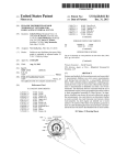
1
USOO8754775B2
(12) United States Patent
(10) Patent N0.:
Holcombe
(54)
(45) Date of Patent:
USE OF OPTICAL REFLECTANCE
3,991,357 A
PROXIMITY DETECTOR FOR NUISANCE
a
N otlce:
'
ZBI
a
3/1981 Webb et a1. ................. .. 340/629
4,313,110 A *
1/1982
Wayne T. Holcombe, Mounta1nV1eW,
4,335,347 A
6/1932 Levine
CA (US)
4,408,711 A
4,615,380 A
10/1983 Levine
10/1986 Beckey
4,674,027 A
6/1987 Beckey
(73) Assignee: Nest Labs, Inc., Palo Alto, CA (US)
*
Is<ucllflrczy1<
a
4,257,039 A
_
Inventor:
Jun. 17, 2014
11/1976 Kaminski
2
MITIGATION IN SMOKE ALARMS
(75)
US 8,754,775 B2
4,685,614 A
4,751,961 A
s u bj ect to anyd'1sc 1 a1mer,t
'
h etermo f t hi s
8/1987 Lev1ne
6/1988 Levine et al.
_
patent is extended or adjusted under 35
(commued)
U.S.C. 154(b) by 777 days.
FOREIGN PATENT DOCUMENTS
(21) App1.No.: 12/727,983
CA
.
2202008
EP
(22)
F11ed:
(65)
Prior Publication Data
US 2010/0238036 A1
Sep. 23, 2010
Subulak et a1. ............. .. 340/527
2/2000
196069
Mar. 19, 2010
12/1991
_
(Cont1nued)
OTHER PUBLICATIONS
Aprilaire Electronic Thermostats Model 8355 User’s Manual,
Research Products Corporation, Dec. 2000, 16 pages.
Related U_s_ Application Data
(60) Provisional application No. 61/162,193, ?led on Mar.
20, 2009.
(Continued)
Primary Examiner * Steven Lim
(51)
Int“ Cl“
Assistant Examiner * Sisay Yacob
(52)
G083 17/10
U‘s‘ Cl“
(200601)
(74) Attorney, Agent, or Firm *Kilpatrick Townsend &
Stockton LLP
USPC .... .. 340/629; 340/628; 340/630; 340/309.16;
73/2333; 73/2335; 73/35.01; 250/200; 250/554;
116/67 R; 116/101; 116/216
(58)
Field of Classi?cation Search
ABSTRACT
USPC ,,,,,,,,,, ,, 340/6284630, 57 74584, 587, 309,16,
detecting smoke and generating a detection signal responsive
340/527; 73/2333, 2335, 5301; 250/554,
thereto. Proximity detection circuitry generates a proximity
250/200; 356/441; 1 16/ 101, 216, 67 R
See application ?le for complete search history,
detection signal responsive to detection of an object Within in
a selected distance of the smoke alarm. Alarm generation
circuitry generates an audible alarm responsive to the detec
tion signal. The audible alarm may be deactivated for a pre
determined period of time responsive to at least one proximity
detection Signal'
(56)
References Cited
U.S. PATENT DOCUMENTS
2,101,637 A
12/1937 Davis
3,934,145 A *
104
(57)
A smoke alarm comprises smoke detection circuitry for
\
1/1976 Dobrzanski et al. ........ .. 250/381
14 Claims, 3 Drawing Sheets
ALAR M
IONIZATION
SENSOR
GENERATION
SPEAKER
C | RC U ITRY
T E ST
110/
BATTERY
CIRCUIT
\108
/
106
US 8,754,775 B2
Page 2
(56)
References Cited
U.S. PATENT DOCUMENTS
4,857,895
4,897,798
4,975,684
5,088,645
5,211,332
5,240,178
5,244,146
5,250,904
5,395,042
5,476,221
5,499,196
5,555,927
5,611,484
5,801,625
5,808,294
5,902,183
5,909,378
5,918,474
5,977,964
6,062,482
6,066,843
6,095,427
6,098,893
6,111,511
6,216,956
6,349,883
6,356,204
6,370,894
6,415,205
6,478,233
6,619,055
6,645,066
6,769,482
6,990,821
7,024,336
7,109,879
7,149,729
7,188,482
7,379,791
RE40,437
7,469,550
7,579,945
7,623,028
7,644,869
7,702,424
7,784,704
7,802,618
7,848,900
7,854,389
7,994,928
8,010,237
8,016,205
8,019,567
8,037,022
8,090,477
8,091,375
8,098,166
8,131,497
8,174,381
8,180,492
8,219,249
2001/0038337
2004/0164238
2004/ 0249479
2005/0090915
2005/0128067
2005/0150968
2005/0189429
2005/0192915
2005/0280421
2006/0186214
2006/0196953
2007/0080819
2007/0115902
2007/0205297
>
A1
A1
A1
A1
A1
A1
8/1989
1/1990
12/1990
2/1992
5/1993
8/1993
9/1993
10/1993
3/1995
12/1995
3/1996
9/1996
3/1997
9/1998
9/1998
5/1999
6/1999
7/1999
11/1999
5/2000
5/2000
8/2000
8/2000
8/2000
4/2001
2/2002
3/2002
4/2002
7/2002
11/2002
9/2003
11/2003
8/2004
1/2006
4/2006
9/2006
12/2006
3/2007
5/2008
7/2008
12/2008
8/2009
11/2009
1/2010
4/2010
8/2010
9/2010
12/2010
12/2010
8/2011
8/2011
9/2011
9/2011
10/2011
1/2012
1/2012
1/2012
3/2012
5/2012
5/2012
7/2012
11/2001
8/2004
12/2004
4/2005
6/2005
7/2005
9/2005
9/2005
12/2005
8/2006
9/2006
4/2007
5/2007
9/2007
Kaprelian
Cler
Guttinger et al. ........... .. 340/587
Bell
Adams
Dewolf et al.
Jefferson et al.
Salander et al.
............ .. 324/430
Riley et al.
Seymour
Pacheco
Shah
Uhrich
Wang .......................... .. 340/ 506
Neumann
D’Souza
De Milleville
Khanpara et al.
Williams et al.
Gauthier et al.
Scheremeta
Hoium et al.
Berglund et al.
Sivathanu et al.
Ehlers et al.
Simmons et al.
Guindi et al.
Thompson et al.
Myron et al.
Shah
Addy
Gutta et al.
Wagner et al.
Singh et al.
Salsbury et al.
Stults et al.
Kaasten et al.
Sadegh et al.
Tamarkin et al.
Rosen
2007/0266575
2008/0015742
2008/0183335
2008/0191045
2008/0273754
2008/0317292
2009/0171862
2009/0254225
2009/0259713
2009/0297901
2009/0327354
2010/0019051
2010/0025483
2010/0070084
2010/0070086
2010/0070234
2010/0084482
2010/0167783
A1
A1
A1
A1
A1
A1
A1
A1
A1
A1
A1
A1
A1
A1
A1
A1
A1
A1
2010/0179704
2010/0211224
2010/0238036
2010/0262298
2010/0262299
2010/0280667
2010/0289643
2010/0308119
2010/0318227
A1
A1
A1
A1
A1
A1
A1
A1
A1
2011/0046792 A1
2011/0046805 A1
2011/0046806
2011/0077896
2011/0151837
2011/0160913
2011/0185895
2011/0307103
2011/0307112
2012/0017611
2012/0065935
2012/0085831
Hoglund et al.
Cannon et al.
Harter
Simon et al.
Nash
Kulyk et al.
Poth et al.
Harter
Hick et al.
Baker et al.
Harrod et al.
Boucher et al.
Blumrich et al.
Kilian et al.
Resnick et al.
Rosen
Hoeynck et al.
Steinberg et al.
Harrod et al.
Steinberg et al.
Kennedy et al.
Alameh et al.
7/2010 Ozog
8/2010 Keeling et al.
9/2010 Holcombe
10/2010 Johnson et al.
10/2010
11/2010
11/2010
12/2010
12/2010
Cheung et al.
Steinberg
Trundle et al.
Steinberg et al.
Steinberg et al.
2/2011 Imes et al.
2/2011 Bedros et al.
2/2011
3/2011
6/2011
6/2011
8/2011
12/2011
12/2011
1/2012
3/2012
4/2012
Nagel et al.
Steinberg et al.
Winbush, III
Parker et al.
Freen
Cheung et al.
BarrilleauX
Coffel et al.
Steinberg et al.
Kopp
2012/0101637 A1
4/2012 Imes et al.
2012/0158350 A1
2012/0221151 A1
6/2012 Steinberg et al.
8/2012 Steinberg
2012/0252430 A1
10/2012 Imes et al.
FOREIGN PATENT DOCUMENTS
Chapman, Jr. et al.
Richter et al.
Kates
A1
A1
A1
A1
A1
A1
A1
A1
A1
A1
11/2007
1/2008
7/2008
8/2008
11/2008
12/2008
7/2009
10/2009
10/2009
12/2009
12/2009
1/2010
2/2010
3/2010
3/2010
3/2010
4/2010
7/2010
JP
JP
JP
59106311
01252850
09298780
6/1984
10/1989
11/1997
OTHER PUBLICATIONS
Steinberg et al.
Ahmed
Richmond
Cheung et al.
Drew
Steinberg et al.
Rahman et al.
Steinberg
Braeburn 5300 Installer Guide, Braeburn Systems, LLC, Dec. 9,
2009, 10 pages.
Braeburn Model 5200, Braeburn Systems, LLC, Jul. 20, 2011, 11
pages.
Ecobee Smart Si Thermostat Installation Manual, Ecobee, Apr. 3,
2012, 40 pages.
Crawford
Ecobee Smart Si Thermostat User Manual, Ecobee, Apr. 3, 2012, 44
Lang
pages.
Steinberg et al.
Ecobee Smart Thermostat Installation Manual, Jun. 29, 2011, 20
Imes et al.
pages.
Steinberg
Ecobee Smart Thermostat User Manual, May 11, 2010, 20 pages.
Electric Heat Lock Out on Heat Pumps, Washington State University
Harrod et al.
Wickstead et al. .......... .. 340/628
Xu et al.
Shorrock
GeiwitZ
Zakrewski
Shearer
Breeden
Ahmed et al.
Yomoda et al.
Simon et al.
Simon et al.
Marks et al. ................ .. 340/628
Shamoon et al.
Finkam et al.
Extension Energy Program, Apr. 2010, pp. 1-3.
Honeywell Installation Guide FocusPRO TH6000 Series, Honeywell
International, Inc., Jan. 5, 2012, 24 pages.
Honeywell Operating Manual FocusPRO TH6000 Series, Honeywell
International, Inc., Mar. 25, 2011, 80 pages.
Honeywell Prestige IAQ Product Data 2, Honeywell International,
Inc., Jan. 12,2012, 126 pages.
Honeywell Prestige THX9321 and TXH9421 Product Data,
Honeywell International, Inc., 68/0311, Jan. 2012, 126 pages.
Honeywell Prestige THX9321-9421 Operating Manual, Honeywell
International, Inc., Jul. 6, 2011, 120 pages.
Hunter Internet Thermostat Installation Guide, Hunter Fan Co., Aug.
14, 2012, 8 pages.
US 8,754,775 B2
Page 3
(56)
References Cited
OTHER PUBLICATIONS
Introducing the New Smart Si Thermostat, Datasheet [online].
Ecobee, Mar. 2012 [retrieved on Feb. 25, 2013]. Retrieved from the
Internet: <URL: https://www.ecobee.com/solutions/home/smart-si/
>, Mar. 12, 2012, 4 pages.
Lennox ComfortSense 5000 Owners Guide, Lennox Industries, Inc.,
Feb. 2008, 32 pages.
Lennox ComfortSense 7000 Owners Guide, Lennox Industries, Inc.,
May 2009, 15 pages.
Lennox iComfort Manual, Lennox Industries, Inc., Dec. 2010, 20
pages.
Venstar T5800 Manual, Venstar, Inc., Sep. 7, 2011, 63 pages.
VisionPRO TH8000 Series Installation Guide, Honeywell Interna
tional, Inc., Jan. 2012, 12 pages.
VisionPRO TH8000 Series Operating Manual, Honeywell Interna
tional, Inc., Mar. 2011, 96 pages.
VisionPRO Wi-Fi Programmable Thermostat, Honeywell Interna
tional, Inc. Operating Manual, Aug. 2012, 48 pages.
White Rodgers (Emerson) Model 1F81-261 Installation and Operat
ing Instructions, White Rodgers, Apr. 15, 2010, 8 pages.
White Rodgers (Emerson) Model IF98EZ-1621 Homeowner’s User
Guide, White Rodgers, Jan. 25, 2012, 28 pages.
Allen et al., “Real-Time Earthquake Detection and Hazard Assess
ment by ElarmS Across California”, Geophysical Research Letters,
vol. 36, LO0B08, 2009, pp. 1-6.
LuX PSPU732T Manual, Lux Products Corporation, Jan. 6, 2009, 48
Deleeuw, “Ecobee WiFi Enabled Smart Thermostat Part 2: The Fea
pages.
tures
NetX RP32-WiFi Network Thermostat Consumer Brochure, Net
homenetworkenabled.com/contentphp?136-ecobee-WiFi-enabled
work Thermostat, May 2011, 2 pages.
NetX RP32-WiFi Network Thermostat Speci?cation Sheet, Network
Thermostat, Feb. 28, 2012, 2 pages.
RobertShaw Product Manual 9620, Maple Chase Company, Jun. 12,
2001, 14 pages.
RobertShaw Product Manual 9825i2, Maple Chase Company, Jul.
17, 2006, 36 pages.
SA720 Smoke Alarm User Manual, First Alert, Aug. 2007, 6 pages.
Smoke Alarm User Manual, Kidde, i9060, Dec. 1, 2009, 2 pages.
SYSTXCCUIZOl-V In?nity Control Installation Instructions, Car
rier Corp, May 31, 2012, 20 pages.
T8611G Chronotherm IV Deluxe Programmable Heat Pump Ther
mostat Product Data, Honeywell International Inc., Oct. 1997, 24
pages.
TB-PAC, TB-PHP, Base Series Programmable Thermostats, Carrier
Corp, May 14,2012, 8 pages.
The Perfect Climate Comfort Center PC8900A W8900A-C Product
Data Sheet, Honeywell International Inc, Apr. 2001, 44 pages.
TP-PAC, TP-PHP, TP-NAC, TP-NHP Performance Series AC/HP
Thermostat Installation Instructions, Carrier Corp, Sep. 2007, 56
Review”,
Retrieved
from
<URL:
http://www.
Smart-Thermostat-Part-2-The-Features-review>, Dec. 2, 2011, 5
pages.
Gao et al., “The Self-Programming Thermostat: Optimizing Setback
Schedules Based on Home Occupancy Patterns”, In Proceedings of
the First ACM Workshop on Embedded Sensing Systems for Energy
Ef?ciency in Buildings, Nov. 3, 2009, 6 pages.
Loisos et al., “Buildings End-Use Energy Ef?ciency: Alternatives to
Compressor Cooling”, California Energy Commission, Public Inter
est Energy Research, Jan. 2000, 80 pages.
Lu et al., “The Smart Thermostat: Using Occupancy Sensors to Save
Energy in Homes”, In Proceedings of the 8th ACM Conference on
Embedded Networked Sensor Systems, Nov. 3-5, 2010, pp. 211-224.
Mozer, “The Neural Network House: An Environmental that Adapts
to its Inhabitants”, AAAI Technical Report SS-98-02, 1998, pp.
1 10-1 14.
Rauchwarnmelder, Installation and User Manual [online]. GIRA
[retrieved on Mar. 8, 2013]. Retrieved from the Internet: <URL:
http://download.gira.de/data2/23301210.pdf>.
Rauchwarnmelder, Datasheet [online]. GIRA [retrieved on Mar. 7,
2013]. Retrieved from the Internet: <URL: http://www.gira.de/
pages.
gebaeudetechnik/pro dukte/sicherheit/rauchmelder/
Trane Communicating Thermostats for Fan Coil, Trane, May 2011,
rauchwarnmelderdualvds.html>, 14 pages.
32 pages.
Rauchwarnmelder, Design [online]. GIRA [retrieved on Mar. 7,
2013]. Retrieved from the Internet: <URL: http://www.gira.de/
Trane Communicating Thermostats for Heat Pump Control, Trane,
May 2011, 32 pages.
gebaeudetechnik/pro dukte/sicherheit/rauchmelder/
Trane Install XL600 Installation Manual, Trane, Mar. 2006, 16 pages.
Trane XL950 Installation Guide, Trane, Mar. 2011, 20 pages.
rauchwarnmelderdualvds.html?vid:1145>, 7 pages.
Venstar T2900 Manual, Venstar, Inc., Apr. 2008, 113 pages.
* cited by examiner
US. Patent
Jun. 17, 2014
Sheet 1 0f3
US 8,754,775 B2
102
/
104\ 'OSNE'ilgggN
ALARIVI
GENERATION
SPEAKER f106
CIRCUITRY
TEST
FIG. I
202
/
204\
gFE’L'ggF:
ALARM
GENERATION
CIRCUITRY
TEST
FIG. 2
SPEAKER f206
US. Patent
Jun. 17, 2014
Sheet 3 0f3
US 8,754,775 B2
ALARM
502
\
PROXIMITY
CIRCUIT
= MITIGATION
FUNCTIONS
~
f504
BATTERY
TEST
\506
FIG. 5
TIT
MONITOR FOR
PROXIMITY ACTUATION
DETECT
ACTUATION
ALTER ALARM TONE
ALARM
ACTIVATED
PRIORITY
DETECTED
BATTERY
DISABLE ALARM
[610
f612
LOW ALARM
PERFORM BATTERY
622/
‘
BATTERY LOW
INDICATION
CHECK
BATTERY
LOW
/
620
BATTERY OK
626/
I
PERIOD Y
EXPIRED
INDICATION
I
FIG. 6
ENABLE ALARM
\616
US 8,754,775 B2
1
2
USE OF OPTICAL REFLECTANCE
PROXIMITY DETECTOR FOR NUISANCE
MITIGATION IN SMOKE ALARMS
alarm. This is of course a most irritating time for this to occur.
Additionally, the beep is very dif?cult to locate since the beep
is short and a single high frequency tone. The beep is short to
CROSS-REFERENCE TO RELATED
APPLICATIONS
mostly depleted battery. The alert transducer uses a single
high frequency, typically around 3 kilohertz due to the need to
enable up to a week or more of low power battery alert on a
produce a very high output from a small transducer which
necessitates the use of a high frequency resonate transducer.
Due to the re?ections and use of half wavelengths shorter than
the distance between the human ears, it is very difficult to
localize the source which may present a problem since most
homes normally include a number of smoke alarms.
Thus, there is a need to provide an improved method for
temporarily mitigating an undesired activation of a smoke
This application claims the bene?t of US. Provisional
Application for Patent Ser. No. 61/162,193, ?led on Mar. 20,
2009, and entitled “USE OF OPTICAL REFLECTANCE
PROXIMITY DETECTOR FOR NUISANCE MITIGA
TION IN SMOKE ALARMS,” the speci?cation of which is
incorporated herein by reference.
TECHNICAL FIELD
alarm and to provide battery check capabilities within the
smoke alarm.
The present invention relates to smoke alarms, and more
particularly to smoke alarms including proximity detectors
for controlling operation of the smoke alarm.
SUMMARY
20
The present invention, as disclosed and described herein, in
one aspect thereof, comprises smoke detection circuitry for
detecting smoke and generating a detection signal responsive
thereto. Proximity detection circuitry generates a proximity
detection signal responsive to the detection of an object
25
within in a selected distance of the smoke alarm. Alarm
BACKGROUND
Smoke alarms are utilized for detecting and warning the
inhabitants of a home or other occupied location of the exist
ence of smoke which may indicate a ?re. Upon detection of
the smoke by the smoke alarm, the device emits a shrill, loud
generation circuitry generates an audible alarm responsive to
the detection signal. The audible alarm may be deactivated for
a predetermined period of time responsive to at least one
alarm that noti?es all individuals within the area that smoke
has been detected and departure from the premises may be
necessary.
While the smoke alarms are very effective at notifying
proximity detection signal.
30
individuals of the possible existence of ?re that is generating
the smoke, certain types of false alarm indications may often
BRIEF DESCRIPTION OF THE DRAWINGS
be very annoying to a user. These false alarms may be trig
For a more complete understanding, reference is now made
gered, for example, by smoke generation within the kitchen
during preparation of a meal. This may cause the creation of
to the following description taken in conjunction with the
35
enough smoke that will set off the smoke alarm causing the
loud, shrill alarm. In this case, a ?re that is dangerous and out
FIG. 1 is a block diagram of a ionization type smoke alarm;
FIG. 2 is a block diagram of an optical type smoke alarm;
FIG. 3 is a more detailed circuit diagram of an optical type
of control is not of concern to the residents so the loud, shrill
smoke alarm will provide more of an annoyance than a ben
e?t. Presently, there exists no method for easily discontinuing
the loud, shrill alarm other than farming the atmosphere in the
smoke alarm;
40
present disclosure;
FIG. 5 illustrates the various functionalities associated
with the smoke alarm including proximity sensor modes of
removing the battery or house power from the smoke alarm in
45
maximum smoke detection capabilities.
An additional problem with existing smoke alarms is the
DETAILED DESCRIPTION
50
Referring now to the drawings, wherein like reference
numbers are used herein to designate like elements through
out, the various views and embodiments of a smoke alarm
that the battery has suf?cient charge. This often requires
having proximity detection operation mode are illustrated
obtaining a ladder or chair for the user to reach the smoke
alarm which has been placed in a substantially high location
55
within the home or building to maximize smoke detection
capabilities. The user is required to push a button that is
located on the smoke alarm to perform a battery check. An
audible signal is provided for an indication of whether or not
the battery is in need of replacement.
An additional related problem relates to the low battery
60
temperature is at a minimum and these conditions maximize
the low battery condition and increase the likelihood of an
and described, and other possible embodiments are
described. The ?gures are not necessarily drawn to scale, and
in some instances the drawings have been exaggerated and/or
simpli?ed in places for illustrative purposes only. One of
ordinary skill in the art will appreciate the many possible
applications and variations based on the following examples
ofpossible embodiments.
condition within a smoke alarm. When the battery reaches a
low power condition, the smoke alarm will commonly beep at
a low duty cycle of around once per minute. Unfortunately,
this beep often occurs in early morning hours when the house
operation; and
FIG. 6 is a ?ow diagram describing the operation of the
smoke alarm including proximity sensor modes of operation.
ing or other high area of the house or building to provide
battery check or low battery condition. In smoke alarms that
are powered by batteries, it is often necessary to periodically
check the battery within the smoke alarm in order to con?rm
FIG. 4 illustrates a block diagram of a smoke alarm includ
ing proximity sensor operation capabilities according to the
area of the smoke alarm in an attempt to remove the smoke
from the area that is causing the smoke alarm to activate or
order to turn it off. Removal of the power source may be
dif?cult as smoke alarms are usually mounted upon the ceil
accompanying Drawings in which:
65
Referring now to the drawings, and more particularly to
FIG. 1, there is illustrated a functional block diagram of a ?rst
type of smoke alarm. The smoke alarm of FIG. 1 utilizes
ionization detection to detect smoke. The alarm generation
circuitry 102 is associated with an ionization sensor 104. The
ionization sensor 104 detects particles of smoke using a small
US 8,754,775 B2
3
4
amount of radioactive americium 241. The radiation gener
inactive. When there is suf?cient smoke to mask the light
from the lamp 304 falling on the LDR 302, the LDR 302
ated by the americium 241 passes through an ionization
chamber within the ionization sensor 104. The ionization
chamber comprises an air-?lled space between two elec
trodes that permit a small constant current between the elec
resistance increases and so does the voltage across the LDR.
This will cause the voltage at the gate of transistor 308 to
increase and turn on transistor 308. This provides a voltage to
power circuit 310 which generates a 5 volt signal to a tone
trodes. Any smoke that enters the chamber absorbs the alpha
particles emitted by the americium 241 which reduces the
ionization and interrupts the current between the electrodes.
generator 312. The tone signal from tone generator 312 is
ampli?ed by an ampli?er 314 which is used to drive the
speaker 306. Diodes 316 and 318 are used to drop the voltage
input to the tone generator 312 from the power circuit 310.
When this condition is detected, the ionization sensor 104
generates an alarm signal to the alarm circuitry 102 that
generates an audible alarm signal that is provided to the
speaker 1 06. Associated with the ionization type smoke alarm
Referring now to FIG. 4, there is illustrated a block dia
gram of a circuit which enables a user to utilize proximity
is test circuitry 108 that enables testing of the present charge
level associated with the battery 110. The battery 110 pro
detection circuitry for temporarily abating an undesired alarm
or performing battery test operations rather than using previ
ously described processes. While the implementation with
vides power to the ionization sensor 104, alarm generation
circuitry 102, speaker 106 and test circuit 108 to power the
smoke alarm.
Referring now also to FIG. 2, there is illustrated an alter
native type of smoke alarm circuitry comprising an optical
smoke alarm. The optical smoke alarm also includes alarm
generation circuitry 202 that is responsive to smoke detection
signals provided by an optical sensor 204. The optical sensor
204 includes a light sensor that includes a light source which
may comprise an incandescent bulb or infrared LED, a lens to
collimate the light into a beam and a photo diode or other
photoelectric sensor for detecting light from the light source.
In the absence of smoke, the light passes in front of the
detector in a straight line. When smoke enters the optical
chamber of the optical sensor 204 across the path of the light
beam, some light is scattered by the smoke particles redirect
ing them at the photo diode or photo sensor, and thus trigger
ing generation of an alarm signal to the alarm circuitry 202.
The alarm generation circuitry 202 will generate the audible
alarm signal to the speaker 206 associated with the alarm
circuitry 202.As with the ionization circuit, the optical smoke
respect to FIG. 4 describes the use of proximity sensor cir
cuitry 402 within an optical type smoke alarm, the proximity
20
operate in a similar manner to the optical alarm described
previously. Alarm generation circuitry 404 generates alarm
signals to a speaker 406 responsive to smoke detection signals
received from optical sensor 408. The optical sensor 408
25
with respect to the optical smoke alarm of FIG. 2.
The optical sensor 408 in addition to detecting smoke is
used for detecting the proximity of a user’ s hand or other item
30
prises a short-range (approximately 6 inches) optical proxim
35
alarm with either the wave of a hand or some other readily
enables testing of the charge within a battery 412. The battery
40
45
easily check the battery charge using the test circuitry. Pres
ently, mitigation of an alarm requires disconnection of the
power source to the smoke alarm in order to discontinue an
50
since either removing power sources to discontinue an undes
cate a ?re or emergency condition has been created. The
55
proximity sensor of the smoke alarm is activated when an
object such as a hand or a broom is brought close to the optical
sensor 408. If the smoke alarm has been activated due to
kitchen smoke or other situations that have been resolved by
60
user to disable the smoke alarm for a short period of time,
such as 3 minutes, to allow the area around the smoke alarm
to air out. A double wave or other more complex detection by
the proximity sensor circuitry 402 and optical sensor 408 may
be accomplished in a short period of time, such as less than 10
tions require the user to get out a ladder or stand on a chair to
access the smoke alarm placed in a high location to ensure its
optimal performance.
human intervention, proximity detection would enable the
FIG. 3 illustrates a schematic diagram of an optical smoke
duces an audible alarm from speaker 306 when smoke is
detected. When there is no smoke, the light from the lamp 304
falls directly upon the LDR 302. The LDR resistance will be
low, and the voltage across the LDR will be below 0.6 volts.
Transistor 308 will be turned off in this state and the circuit is
the smoke alarm may provide a number of proximity control
ler functionalities. These are generally illustrated in FIG. 5. A
number of proximity controlled functions 502 may be pro
vided using the proximity sensor 402. The proximity con
trolled functions include the alarm mitigation function 504
and the battery test function 506. The alarm mitigation func
tion 504 enables a temporary discontinuation of the audible
alarm in situations when an undesired activation of the alarm
has occurred. This would occur for example, when a small
amount of smoke created within a kitchen that does not indi
the smoke alarm that requires the user to be able to physically
touch the smoke alarm. This often presents a great challenge
detection alarm based upon an LDR (light detecting resistor)
302 and lamp 304 pair for sensing smoke. The alarm works by
sensing the smoke produced during a ?re. The circuit pro
412 provides power to each of the components within the
smoke alarm circuit.
Utilizing a combination of the proximity sensor circuitry
402, optical sensor 408 and alarm generation circuitry 404,
heating element of the oven, etc., or the ability to quickly and
ired alarm or pressing a button to perform battery test opera
ity sensor that in conjunction with the proximity sensor cir
cuitry 402 may be used to control operations of the smoke
available object such as a broom. The test circuitry 410
As described previously, some issues arising with existing
smoke alarms, be they ionization or optical type smoke
alarms, arise from the creation of false alarm situations such
undesired alarm. Additionally, any type of test of the battery
charge requires pushing of a button on the external surface of
in conjunction with the proximity sensor circuitry 402. The
proximity sensor circuitry 402 detects when a hand or for
example, a broom or other item are being waved in close
proximity to the smoke alarm. The optical sensor 408 com
210. The battery 210 is responsible for powering all of the
components of the optical smoke alarm including the alarm
circuitry 202, optical sensor 204, speaker 206 and test circuit
as, for example, when a small amount of smoke is created
within the kitchen due to burning toast, food falling on the
generates the smoke detection signal to the alarm generation
circuitry 404 in the same manner as that described previously
alarm utilizes a test circuit 208 to test the charge on the battery
208.
sensor circuitry 402 could also be implemented within the
ionization type circuitry described hereinabove. The smoke
alarm detection capabilities of the smoke alarm of FIG. 4
65
seconds in order to enable assurances that the detection was
for a desired mitigation of the alarm and not some type of
random event occurring during actual smoke detection.
US 8,754,775 B2
5
6
In order to assist a user in temporarily mitigating the alarm,
a momentary change in the audible alarm would be desirable
one for proximity detection and the other for smoke detection
within the optical sensor 408. A light pipe can provide a signal
from the baf?ed smoke detector and also from the outside
for each proximity event that has been detected by the optical
sensor 408 and proximity sensor circuit 402. This would
proximity view. Depending on which LED is driven, the
assist the user in knowing whether they had accurately or
proximity detector is either for re?ectance above a threshold
for either the proximity detection or for smoke and of course
giving a different alarm response. Optionally, an auxiliary
photo diode can be used for the smoke detector portion to
avoid artifacts or issues arising from ambient light. Because
inaccurately waved their hand or broom in the area of the
smoke alarm and provide for an audible indication of aiming
feedback with respect to the proximity detection. After the
appropriate combination of proximity detection events have
been detected by the optical sensor 408 and proximity sensor
circuit 402, the audible alarm would be temporarily discon
tinued.
The smoke alarm commonly beeps at a low duty cycle of
around once per minute when the battery 412 has its charge
fall below a predetermined level. These beeps can often be
very di?icult to locate since the beep is short and comprises a
single high frequency tone. The beep is short to enable up to
the proximity detection technology uses a low duty cycle
controller to make proximity detection measurements every
second or so, this low duty cycle controller can also be used
for the low duty cycle smoke controller which is bene?cial for
reducing battery charge consumption.
Referring now to FIG. 6, there is illustrated a ?ow diagram
describing the operation of the proximity detection controlled
a week or more of low battery alerts to be created on an almost
depleted battery. The alert transducer uses a single high fre
quency chirp typically around 3 kilohertZ due to the need to
produce a very high output from a small transducer. This
necessitates the use of a high frequency resonate transducer.
Due to the re?ections and the use of a half wavelength shorter
than the distance between the human ear, it is often very
dif?cult to locate the source requiring the user to check each
smoke alarm within the house requiring a great deal of time.
20
Once a proximity actuation is detected, inquiry step 606
determines if the smoke alarm is presently activated. If so,
control passes to inquiry step 608 which determines if a
25
The battery test functionality 506 enables a battery test
operation to be performed on the battery 412 within the
smoke alarm without having to manually press a button on the
smoke alarm. The battery test functionality 506 can be uti
predetermined number of proximity activations have been
detected. If not, the alarm tone provided by the smoke alarm
may be altered at step 610 and control returns back to step 602
30
lized in two situations. When a low battery charge chirp is
being emitted by the smoke alarm, the low battery test func
tionality 506 may be used to determine whether a particular
smoke alarm has a low battery charge or whether the battery
presently has su?icient charge. The battery test functionality
506 would similarly be useful for performing the periodic
smoke alarm. Initially, at step 602, the optical sensor 408 and
proximity sensor circuitry 402 monitor for a proximity actua
tion. Inquiry step 604 determines whether there has been a
detection of a proximity actuation. If not, control passes back
to step 602 to continue monitoring for a proximity actuation.
35
to continue monitoring for additional proximity activations.
If inquiry step 608 determines that a predetermined number
of proximity actuations have been detected, the smoke alarm
is disabled at step 612. Inquiry step 614 monitors for the
expiration of a selected period of time. If the period of time
has not yet expired, the process remains at inquiry step 614.
Once the predetermined period of time has expired, control
passes to step 616, wherein the smoke alarm is re-enabled and
battery charge tests that are required to ensure the smoke
control passes back to step 602 to continue monitoring for
proximity actuation. Once the alarm is re-enabled, the smoke
alarm is in working operation.
By utiliZing the proximity sensor circuitry 402, if the
detector can monitor for smoke and react accordingly.
If inquiry step 606 determines that the smoke alarm is not
dying battery. If the battery 412 is suf?ciently charged, a
presently activated, control passes to inquiry step 618 to make
a determination if the battery low alarm is presently active for
the smoke alarm. If so, a battery low indication is audibly
provided from the smoke alarm at step 620. If the battery low
alarm has not been activated, a battery charge check is per
formed at step 622. Inquiry step 624 determines whether the
battery is in a low charge condition. If not, a battery OK
single short beep of a different tone may be created. Thus, if
audible indication is provided at step 626 to indicate a su?i
a user hears a low battery beep, they can use their broom or
cient charge and control passes back to step 602. If inquiry
step 624 determines that the battery is in a low charge condi
tion, the battery low indication is provided at step 620 before
smoke alarm has not been activated to indicate detection of
smoke, the detection of a single proximity event from a hand
or broom by the optical sensor 408 and proximity sensor
circuitry 402 initiates a battery check test. If the battery 412 is
weak, the test circuitry 410 will cause the production of a
40
distinctive series of beeps or a distinctive tone to indicate a 45
hand to quickly and easily check all of the smoke alarms
within their home without having to climb up on a chair or
ladder or remove the devices in order to press a detection
button upon the smoke alarm.
As described previously, smoke alarms generally use either
an ionization chamber or optical smoke detection circuitry or
a combination of both to detect smoke. These differing tech
50
control passes back to step 602 to monitor for additional
proximity actuations.
The above-described solution provides a low cost intuitive
55
niques have distinct advantages and disadvantages. However,
a high performance optical re?ective detector implemented
within the circuit of FIG. 4 including proximity sensor cir
cuitry 402 can readily be adapted to detect re?ectance from
smoke and to provide proximity detection data since both
detections are equivalent low re?ectance functions. The prox
imity detector is more sophisticated since it must deal with
improves safety since users often remove batteries or take
down smoke alarms that are producing spurious alarms or low
battery beeping alarms. Users will also take down unaffected
60
ambient light while the conventional optical smoke detector
does not have to cancel ambient light since it looks for re?ec
tions from smoke in an optically baf?ed compartment which
blocks out ambient light but allows the entry of smoke. A
re?ectance proximity detector can drive two different LEDs,
battery alarm control system to limit nuisance alarms within
the smoke alarm and enables ease of battery charge checking
using a proximity detection control process. The system also
smoke alarms since the user cannot localize the beep associ
ated with the alarm and then do not replace the alarm. Con
sumers do not check battery levels if the smoke alarm is out of
reach. Additionally, use of an optical re?ection proximity
control system is better than a capacitive proximity system
65
since convenient hand extension devices such as brooms
would not work to activate a capacitive sensor which senses a
conductive object such as the human hand or body.
US 8,754,775 B2
8
7
It will be appreciated by those skilled in the art having the
bene?t of this disclosure that this smoke alarm having prox
imity detection operation mode provides an improved method
for controlling operation of a smoke alarm. It should be
understood that the drawings and detailed description herein
determined period of time and within the selected dis
tance of the smoke detector and while detecting the
smoke.
7. The method of claim 6, further comprising:
reactivating the audible alarm after another predetermined
period of time when the smoke is still detected by the
are to be regarded in an illustrative rather than a restrictive
smoke alarm.
manner, and are not intended to be limiting to the particular
forms and examples disclosed. On the contrary, included are
8. The method of claim 6, further comprising:
detecting movement of the object within the selected dis
any further modi?cations, changes, rearrangements, substi
tutions, alternatives, design choices, and embodiments appar
tance when an audible alarm is not being generated;
determining a charge level of a battery associated with the
smoke alarm responsive to the detected movement;
generating a ?rst audible indication when the charge level
of the battery exceeds a predetermined level; and
generating a second audible indication when the charge
level of the battery falls below the predetermined level.
9. The method of claim 6, wherein the step of generating
the audible alarm further includes:
ent to those of ordinary skill in the art, without departing from
the spirit and scope hereof, as de?ned by the following
claims. Thus, it is intended that the following claims be inter
preted to embrace all such further modi?cations, changes,
rearrangements, substitutions, alternatives, design choices,
and embodiments.
generating the audible alarm at a ?rst level responsive to a
What is claimed is:
1. A smoke alarm, comprising:
smoke detection circuitry for detecting smoke and gener
ating a smoke detection signal responsive thereto;
proximity detection circuitry for generating a proximity
detection signal when the proximity detection circuitry
20
a second detected movement when the audible alarm is
at the ?rst level.
10. A method for controlling operation of a smoke alarm,
comprising:
detects a movement of an object within a selected dis
tance of the smoke alarm; and
25
smoke;
detecting movement of an object within a selected distance
of the smoke alarm, wherein the movement is detected
two proximity detection signals are generated within a
30
11. The method of claim 10, wherein controlling operation
of the smoke alarm further includes temporarily deactivating
the audible alarm.
exceeds a predetermined level and generates a second
audible indication when the charge level of the battery
falls below the predetermined level.
40
smoke alarm.
responsive to a ?rst proximity detection signal and generates
of the smoke detector further includes:
detecting movement of the object within the selected dis
45
50
comprising:
detecting smoke with the smoke alarm;
generating an audible alarm responsive to detection of the
using a proximity detection circuit; and
temporarily deactivating the audible alarm when at least
two movements of the object are detected within a pre
tance when an audible alarm is not being generated;
determining a charge level of a battery associated with the
smoke alarm responsive to the detected movement;
generating a ?rst audible indication when the charge level
of the battery exceeds a predetermined level; and
generating a second audible indication when the charge
level of the battery falls below the predetermined level.
14. The method of claim 10, wherein generating the
audible alarm further includes:
generating the audible alarm at a ?rst level responsive to a
smoke;
detecting movement of an object within a selected distance
of the smoke alarm, wherein the movement is detected
12. The method of claim 11, further comprising:
reactivating the audible alarm after another predetermined
period of time when the smoke is still detected by the
13. The method of claim 10, wherein controlling operation
the audible alarm at a second level responsive to a second
proximity detection signal when the audible alarm is at the
?rst level.
4. The smoke alarm of claim 1, wherein the smoke detec
tion circuit comprises an optical detection circuit.
5. The smoke alarm of claim 1, wherein the smoke detec
tion circuit comprises an ionization detection circuit.
6. A method for controlling operation of a smoke alarm,
using a proximity detection circuit; and
controlling operation of the smoke alarm when at least two
movements of the object are detected within a predeter
mined period of time and within the selected distance of
the smoke alarm and while the smoke is detected.
of a battery associated with the smoke alarm; and
wherein the alarm generation circuitry generates a ?rst
audible indication when the charge level of the battery
3. The smoke alarm of claim 1, wherein the alarm genera
tion circuitry generates the audible alarm at a ?rst level
detecting smoke with the smoke alarm;
generating an audible alarm responsive to detection of the
alarm generation circuitry for generating an audible alarm
responsive to the smoke detection signal, wherein the
audible alarm is temporarily deactivated when at least
predetermined period of time and while the smoke
detection signal is received.
2. The smoke alarm of claim 1, further comprising:
battery charge test circuitry for determining a charge level
?rst detected movement of the object; and
generating the audible alarm at a second level responsive to
55
?rst detected movement of the object; and
generating the audible alarm at a second level responsive to
a second detected movement when the audible alarm is
at the ?rst level.