1
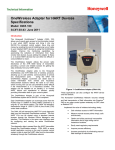
BP-IMFM 2000
BATTERY POWERED
INSERTION MAGNETIC
FLOWMETER
Measurement, data acquisition
and transmission system of flow
and pressure for water networks
with long battery life
9 Flow measurement
BP-IFM2000 is an electromagnetic flow meter that uses
insertion sensor, it is battery powered by a Lithium
battery type LiSOCl2 lasting up to five years and it can
be powered by a 24 VDC power supply too.
It acquires data on an internal 4 Mb memory
(200,000.00 acquisitions) and on an external 4GB
micro SD card: the acquired data, together with the
alarms and the diagnostics can be sent remotely
through a built-in GSM / GPRS modem.
Main Characteristics
9 Optional Pressure measurement
With Battery Powered Insertion Magnetic Flowmeter
2000 (BP-IMFM2000) BM Tecnologie Industriali
developed and introduced in Full Pipe Water Flow
Measurement Market an innovative ALL IN ONE flow
meter.
The software HydroFlux
was developed for the
advanced management of the acquired data, it allows
the creation of master data, tables and graphs, it could
be able to make the budget in a water district and
identify the water losses, it imports and exports the
data.
9 Compact and easy to install
9 Data acquisition on internal memory
and Micro SD card
9 Data transmission via GPRS/GSM/SMS
to a remote system
data
9 Virtual Water Districtualization
9 Leak in Aqueduct
9 Check Fire System
Main Applications
A sophisticated diagnostic system, with a smart user
interface, allows the user to understand quickly if the
measurement is correct and, if not, to identify the
problems.
9 Battery life: up to 5 years, expandable
up to 10 years
9 Software
“HydroFlux”
for
management and configuration
The IP68 protection grade of the main unit and the
IP68 protection grade of the sensors complete the
excellent performances of this flow meter.
The advanced configuration menu can guide in a few
steps, through a graphic LCD display and a keyboard or
using software HydroFlux, even a few experienced
operator about how to use BP-IMFM2000.
9 Protection IP68
9 Calibration of Numerical Models
9 Measurement campaigns on Long and
Short Periods in Aqueduct
9 Water Balance
9 Pumping Station Control
9 Waste Water Treatment Plants
9 Hydroelectric Power Stations
9 Industrial Process Monitoring
9 Billing purposes
9 Flow Surveys
9 Flow Profiling
B.M. Tecnologie Industriali srl
Via Praimbole 13
35010 LIMENA (PD)
Cod.Fis./P.Iva IT02459940280
Tel. +39 (0) 49 884.16.51
Fax +39 (0) 49 884.16.54
E-Mail [email protected]
Web www.bmtecnologie.it
BBP-IMFM 2000
Technical Features
The basis for the operation of electromagnetic flowmeters are Faraday’s Laws of Induction.
A voltage is induced in a conductor as it moves through a magnetic field. This measurement principle is
applied to a conductive fluid which flows in a pipe through which a magnetic field is generated
perpendicular to the flow direction (see Fig. 1).
The voltage which is induced in the fluid is measured at two electrodes located diametrically opposite to
each other. This signal voltage UE is proportional to the magnetic induction B, the electrode spacing D and
the average fluid velocity v.
Noting that the magnetic induction B and the electrode spacing D are constant values indicates that a
proportionality exists between the signal voltage UE and the average flow velocity v.
The equation for calculating the volume flowrate shows that the signal voltage UE is linear and
proportional to the volume flowrate.
Fig. 1
B.M. Tecnologie Industriali srl
Via Praimbole 13
35010 LIMENA (PD)
Cod.Fis./P.Iva IT02459940280
Tel. +39 (0) 49 884.16.51
Fax +39 (0) 49 884.16.54
E-Mail [email protected]
Web www.bmtecnologie.it
BBP-IMFM 2000
Technical Features
ELECTRONIC UNIT
I/O
Flow sensor inputs
Inputs for electromagnetic sensor
Digital Input
Programmable by the user
Output Signals
• Active analogue output 4-20 mA (requiring external 24VDC power);
• Digital output for pulses maximum 1000 Hz duty cycle max 50% for instant
load, positive only, positive and negative;
• Programmable digital output for:
- Maximum pulses 1000 Hz duty cycle max 50% for negative load;
- Negative load indication;
- Cumulative alarm
• Digital output in active frequency 0-10 kHz (requiring external 24VDC
power);
• All outputs are opto-isolated.
• Pulse outputs with a maximum capacity of ±35VDC 50 mA.
Pressure sensor input
1 analog input 0÷10V
Serial port
• IIrDA interface for communicating with laptop or hand held communicator,
and dedicated SW for programming, displaying and downloading data.
• MODBUS RTU interface on RS 485.
Accuracy
1 % of the read value (minimum velocity 2,0 mm/s)
Repeatability
0.1% of the read value (minimum velocity 2,0 mm/s)
Sampling Frequency
Programmable 5, 3, 1, 1/15, 1/30, 1/60, 1/120, 1/240, 1/480 Hz.
Measuring Stabilization Time
3 seconds
Electrical Conductivity
20 µS/cm minimum
Recommended Velocity
-10 to 10 m/s
POWER SUPPLY
Internal Battery
• Lithium, type LiSOCl2
• Expected lifetime with working temperature of 0…50°C (32/122°F):
Internal battery pack 3-6 years
Internal and external battery pack 6-10 years
External Power source
Low tension: 11÷24V AC/DC
Power Consumption
3 - Watt
ACQUISITION DATA MEMORY
Flash
4 MB – 200.000 lines of data (one line includes: instant flow, 2 counters, date,
time, temperature). Completely programmable both in
terms of content and acquisition times.
Micro SD card
4GB
Diagnostics Data Logger
64 kB EEPROM, 2000 lines of data (one line includes: Date, time, temperature, error codes, user actions with changes made).
Not programmable and tamper/reset proof.
REAL TIME CLOCK
Real Time Clock
Buffered with internal battery
MODEM and SIM CARD
Bandwidth
QuadBand GSM: 900/1800 e 850/1900 MHz
Functions
SMS, GSM, GPRS
Standard
Compatible with controls AT standard 07.07 e 07.05
DISPLAY e KEYBOARD
Number of characters
B.M. Tecnologie Industriali srl
Via Praimbole 13
35010 LIMENA (PD)
Cod.Fis./P.Iva IT02459940280
•
•
•
•
•
Graphic LCD - 128x64 pixels, 50x25mm visual area
Backlit white colour, programmable backlighting.
Simultaneous display of a counter + instant variable + status flags.
Counters with 8 mm high characters for reliable and easy reading.
Programmable display content.
Tel. +39 (0) 49 884.16.51
Fax +39 (0) 49 884.16.54
E-Mail [email protected]
Web www.bmtecnologie.it
BBP-IMFM 2000
Technical Features
Menu languages
Italian, English, Spanish
No. of keys
4 keys
ENVIRONMENTAL
Temperature
• Process: -10°C to 70°C
• Ambient: -20°C to 60°C
• Storage: -30°C to 70°C
Protection
IP68
PROGRAMMING
Programming mode
• With push buttons on board of converter for non-billing applications.
• By IrDA interface and laptop with dedicated software or via RS485 and
MODBUS RTU protocol; available for all applications including billing and
custody transfer.
MECHANICAL
Case/Material
Aluminium epoxy painted IP 67/68, with front window in toughened glass.
Size and weight
Cylindrical: Length 249 mm; Diameter 117 mm – Weight 3.5 kg
MEASUREMENT UNITS
Metric /Imperial
Settable individually for counters, flow indication, pulse emission.
• Selectable volume units: ml, cl, dl, l, dal, hl, m3 , in3, ft3, gal, US gal, bbl,
oz.
COMPLIANCE STANDARDS
Approvals and Certifications
BP-IMFM 2000 unit meets all the requirements established by the EC
directives. The manufacturer certifies the success of the qualification tests by
applying the CE mark.
For Main Unit:
• Electromagnetic compatibility: Directive 89/336/EEC, EN 613261:2006
• Low voltage directive : Directive 2006/95/EC
• Custody Transfer : MI-001 and OIML R-49 (certification pending)
For Insertion Sensor:
• CEI EN 61010-1
• UNI EN ISO 6817
• EN 14154
• EN 50081 - 1
MAIN UNIT DIMENSIONS
117 mm
Rotation of 90°
249 mm
B.M. Tecnologie Industriali srl
Via Praimbole 13
35010 LIMENA (PD)
Cod.Fis./P.Iva IT02459940280
Tel. +39 (0) 49 884.16.51
Fax +39 (0) 49 884.16.54
E-Mail [email protected]
Web www.bmtecnologie.it
BBP-IMFM 2000
Technical Features
ELECTROMAGNETIC INSERTION SENSOR
Material
• AISI 304 stainless steel. It is supplied together with a bronze muff. In
the separate version (with cable) they have an IP68 protection degree for
immersion in 1.5 meters.
The junction box placed on top of the sensor, has two glands for the
cables connection. The sensors are available with several lengths, to fit various
pipe diameters.
• The head of the sensors is in PTFE and in contact with the fluid
Electrodes
AISI 316 L stainless steel.
Assembly
Insertion sensors must be installed on empty pipes.
• For pipes with DN>80 to DN500 through a 1.1/4" threaded brass muff.
• For pipes with DN40 to DN≤80 through a 1” threaded brass muff.
(The muff has to be welded to the pipe to which connect the sensor).
The probe has to be inserted into the tube for 1/8 of its internal
diameter.
When installing the sensor, the minimum distances
of
10
diameters
upstream and 5 diameters downstream must be respected, making a 90°
angle with the pipe as per fig. 2.
Total Length
317 mm
Parts in contact with the liquid
• Head of sensors in PTFE
• Electrodes (to appraise after muff welding)
• Pipe end in AISI 304 Stainless Steel
Electric Connections
Cable gland PG11 + Terminal Block + sealing resin
Weight
2 kg
PIPES
Internal diameter
40…500 mm
Hydraulic conditions
The upstream straight section must be greater than 10 diameters, the
downstream section should be greater than 5 diameters
MEASURED FLUID
Type
All conductive fluids, minimum conductivity 20 µs/cm2.
Liquid Temperature
-40°C...+180°C
ELECTROMAGNETIC SENSOR
Type
Insertion type
Cable length
Max. 10 mt with battery power, Max. 100 mt with 24VDC power supply
Protection
IP68
Fig. 2 - Installation
B.M. Tecnologie Industriali srl
Via Praimbole 13
35010 LIMENA (PD)
Cod.Fis./P.Iva IT02459940280
Tel. +39 (0) 49 884.16.51
Fax +39 (0) 49 884.16.54
E-Mail [email protected]
Web www.bmtecnologie.it
BBP-IMFM 2000
Technical Features
INSERTION SENSOR DIMENSIONS
Overall Dimensions
• 1 – Female Coupling: 1” BSP / NPT for pipes DN40...≤80; 1.1/4" BSP / NPT for pipes DN80...500 (see below
picture)
• 2 – 1.1/4" Male BSP / NPT fixing device for pipe size >DN80; 1” for pipe seize < DN80
• 3 – Blocking Nut
• 4 – Insertion Sensor
• 5 – Connection Box
• LC – General length fixing device (to appraise after muff welding)
• RL – Available travel = Ltot - Li - S – LC
• Li – Insertion length = (De - 2S) / 8
measures in mm
B.M. Tecnologie Industriali srl
Via Praimbole 13
35010 LIMENA (PD)
Cod.Fis./P.Iva IT02459940280
Tel. +39 (0) 49 884.16.51
Fax +39 (0) 49 884.16.54
E-Mail [email protected]
Web www.bmtecnologie.it
BBP-IMFM 2000
Technical Features
PRESSURE MEASUREMENT (OPTIONAL)
Nominal Range
0..0,10 - 0,25 - 0,40 - 0,60 - 1,00 - 1,60 - 0..2,50 - 4,00 - 6,00 - 10,0 - 16,0 25,0 - 40,0 - 60,0 - 100,0 Bar (user selectable)
Accuracy
0,5% with a range up to 0,6 Bar - 0,35 % with a range over 0,6 Bar
Temperature
-25°C~ +125°C
Protection
IP68
Cable length
5 m (incremental length at step of 5 m) - Max. 200 m
Engineering unit
Bar, PSI
PRESSURE SENSOR DIMENSIONS
Ø 35 mm
82 mm
14 mm ½” GAS
BASIC EQUIPMENT BP-IMFM 2000
Quantity
Description
1
Battery Powered Main Unit
1
Insertion Sensor
1
Pressure Sensor (Optional)
1
Configuration and data management Software:
“HydroFlux”
1
User manual
ACCESSORIES and SPARE PARTS FOR BP-IMFM 2000
Description
External battery pack for BP-IMFM2000, type:
LiSOCl2
Protection IP68
Micro SD card
Capacity: 4 GB
B.M. Tecnologie Industriali srl
Via Praimbole 13
35010 LIMENA (PD)
Cod.Fis./P.Iva IT02459940280
Tel. +39 (0) 49 884.16.51
Fax +39 (0) 49 884.16.54
E-Mail [email protected]
Web www.bmtecnologie.it
BBP-IMFM 2000
Ordering Code
ORDERING CODE
BP - IMFM 2000
1
-
-
-
-
-
Data transmission
Micro SD card (series)
BlueTooth or RF Module (not yet available)
1
1
FLOW SENSOR
Insertion sensor for pipes from DN40...500
1
CABLE LENGHT FOR FLOW SENSOR
Compact Version (NO CABLE)
0
0
Indicate the number of 5 m extensions
Battery power: max. 10 mt
24VDC power supply: max. 100 mt
X
X
PRESSURE SENSOR (OPTIONAL)
NO Pressure Sensor
0
0
0..0,10 Bar
0
1
0..0,25 Bar
0
2
0..0,40 Bar
0
3
0..0,60 Bar
0
4
0..1,0 Bar
0
5
0..1,6 Bar
0
6
0..2,5 Bar
0
7
0..4,0 Bar
0
8
0..6,0 Bar
0
9
0..10 Bar
1
0
0..16 Bar
1
1
0..25 Bar
1
2
0..40 Bar
1
3
0..60 Bar
1
4
0..100 Bar
1
5
CABLE LENGHT FOR PRESSURE SENS.
5 m (standard)
0
0
Indicate the number of 5 m extensions
X
X
B.M. Tecnologie Industriali srl
Via Praimbole 13
35010 LIMENA (PD)
Cod.Fis./P.Iva IT02459940280
Tel. +39 (0) 49 884.16.51
Fax +39 (0) 49 884.16.54
E-Mail [email protected]
Web www.bmtecnologie.it
LLB - PTTFM 2000
Software
HydroFlux
Software to manage the data downloaded
from BP-IMFM 2000
The advanced processing and management
of ingoing and outgoing flow data of the
water districts identifies any losses in water
networks by measuring the minimum night
flow. It is possible to display the data in
tabular or graphical form, for an immediate
visualization of trends.
B.M. Tecnologie Industriali srl
Via Praimbole 13
35010 LIMENA (PD)
Cod.Fis./P.Iva IT02459940280
Districts organization
BP-IMFM2000 and build virtual water districts
that can be identified by some stations.
Volumes
You can create measurement stations to
which bind the data downloaded from a
Water balance for leaks detection
Minimum Night Flow
HydroFlux is a software developed for the
configuration, the download and the import
of data from BP-IMFM2000 and their
following automatic analysis to detect, for
example, the losses in a water network.
Data visualization
General description
Software
Data display tabular and graphical form
Tel. +39 (0) 49 884.16.51
Fax +39 (0) 49 884.16.54
E-Mail [email protected]
Web www.bmtecnologie.it


![Overview cPR67 and cPR84 [v00]](http://vs1.manualzilla.com/store/data/005648847_1-d158a5d3d4b92d14c7a3179652b88ffd-150x150.png)