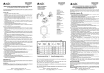
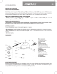
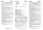
1
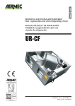
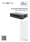
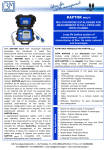
TTFM100B SERIES
TRANSIT TIME FLOWMETER- PORTABLE TYPE
DESCRIPTION
The Transit Time Flowmeter of TTFM100B series measures flowrate by
calculating the spreading time of an ultrasonic wave in a liquid, going
upstream and downstreamgo into a full pipe.
This flowmeter is mostly used to measured the flowrate of homogeneus
fluids , with a very little percentage of suspended solids and possibly
without gas bubbles.
Its peculiar installation makes this devices suitable for measuring
aggressive fluids (acids, basic and dissolvents) or very soiling fluids(oil
and fuels).
The measuring system is composed of one or more couples of
ultrasonic transducers acoustically coupled to the external pipe’s wall
(it is also possible to use transducers in direct contact with fluid to be
measured) and a portable unit elaborating the sent and received signals
from the transducers. The HOST unit has a DSP microprocessor, it
gives signals to interfacing with the process or the control systems.
Main Characteristics
The TTFM100B series includes a range of ultrasonic flowmeters whose electronics is composed of a single board:
high precision, high fidelity, high competitivity.
The devices main characteristics are:
•Clamp-on sensors: it is not necessary to stop the flow to install them. Or Insertion sensors.
•The device could make the signals gain automatically suitable to the pipe’s diameter and to the measuring conditions.
•0.5% linearity.
•0.2% repeteability.
•4 flow totalizers.
•Battery supply lasting 8 hours in continuous functioning.
•The time difference during the measuring process could be 0.1 ns.
•Ultrasonic transducers with low voltage supply, patened.
•Possibility of saving up to 2000 internal measures, suitable to the selected parameters.
•Analog (4-20 ma), pulses (relays), frequence (OCT) and RS232 outputs.
•All the measures could be driven to the RS232 in order to save data into a PC or a serial printer.
Typical Use
•The TTFM100B flowmeter could be virtually used in a very huge range of measuring. The diameters could go from
DN20 up to DN6000 and the application could be the following:
•Water treatment, slurry and process water pumping;
•Oil and chemical industries;
•Hydro-electric, cooling, anti-fire stations;
•Exploitation industries;
•Food, paper and pharmaceutical industries;
•Car industries;
•Flow balancing;
BM Tecnologie Industriali s.n.c.
Via PRAIMBOLE, 13 – 35010 LIMENA – PADOVA – ITALY
Tel. +39 (0) 49 8841 651 - Fax. +39 (0) 49 8841 654
e-mail: [email protected]
www.bmtecnologie.it
TTFM100B SERIES
Description- Transit Time Flowmeters Working Principle
When the ultrasonic spreads in the liquid, the flow will cause a changing in the spreading time in function of downstream
or upstream current.
The ultrasonic wave going towards the same directions of the flow , increases the spreading speed, while the ultrasonic
wave going towards the opposite side of the flow decreases the spreading speed.
If the difference between the two spreading times is accurately measured, it would be possible to calculate the flow
speed (see the following picture).
2 sensors in direct contact with the pipe’s external surface are used to measure.
One sensor is placed on the upper side of the pipe’s external surface, one sensor is placed on the lower side of the
pipe’s external surface.
The sensors positions could look like a “Z” or like a “V” or a “W”, if the pipe has a small diameter (in the previous picture,
the sensors are “Z” mounted).
The sensors are alternatively used to receive the ultrasonic pulses sent through the way pipe- fluid- pipe.
The difference between the transmitted and received signals upstream and downstream are calculated as follows:
Sensor UP
Remove the outside
covering
Outside covering
Pipe
Inside covering
Q
M ∗D
COS θ
Τ up =
Co + VSIN θ
V=
Sensor DOWN
M ∗D
COS θ
Τ down =
Co − VSIN θ
M ∗D
∆Τ
∗
SIN 2θ Τup ∗ Τdown
Where:
M
D
Ө
Co
Tup
Tdown
Spreading time
Pipe’s internal diameter
Transmission angle
Sound spread speed through the fluid in static conditions
Positive spreading time
Negative spreading time
DT value is the difference of spreading time into a homogenous fluid without gas bubbles.
The equation (3) for calculating the average speed “V” could be used for all the types of fluids in ideal conditions. The
fluid speed measuring is in fact conditioned by different factors which make the precision decrease: for example the
dumps on the pipe’s internal walls: they change the measuring principle of the transit time flowmeter.
TTFM100B series has are a lot of solutions trying to solve these problems, compensating the temperature influence, the
dumped internal walls and the asymmetry in the speed distribution, in order to measure in critical conditions too.
It is possible to adjust the zero point of the device: if the fluid is in static conditions, this operation makes the precision
increase until reaching values near to 0.5%.
BM Tecnologie Industriali s.n.c.
Via PRAIMBOLE, 13 – 35010 LIMENA – PADOVA – ITALY
Tel. +39 (0) 49 8841 651 - Fax. +39 (0) 49 8841 654
e-mail: [email protected]
www.bmtecnologie.it
TTFM100B SERIES
Technical Features
FEATURE
SPECIFICATION
Linearity
0.5%
Repeatability
0.2%
Accuracy
+/- 1% of the reading value > = 0.2 m/s
Response time
From 0 to 999 seconds, set by the user.
Speed
+/- 32 m/s
Pipes diameter
From DN20 to DN 6000
Eng. Unis
Totalizers
Measurable liquids
Meters, Feet, Cubic meters, Cubic feet, USA
Gallons, Imperial Gallons, USA Million
Gallons, set by the user.
7 digit for positive, negative and net
flowrate.
All the liquids (virtually)
Safety
Possible to set a password for blocking the
device.
Display
Graphic dislya4 lines, 16 characters.
Interface
RS232-C from 75 to 57600 BPS. Ientek
protocol compatible with Fuji.
Transducers
S1, M1, L1 on customers request.
Cable lengths
From 2 x 5 m up to 2 x 500 m
Supply
3 x AAA Ni-MH batteries (included) for 8
hours working
Data logger
Internal data logger to save up to 2000 lines
of data.
Manual totalizer
7 digit totalizaer for manual acquisitions and
calibrations.
Housing material
ABS
Housing dimensions
460 (L) x 400 (W) x 110 (H) mm
Weight
4.5 kg batteries included
BM Tecnologie Industriali s.n.c.
Via PRAIMBOLE, 13 – 35010 LIMENA – PADOVA – ITALY
Tel. +39 (0) 49 8841 651 - Fax. +39 (0) 49 8841 654
e-mail: [email protected]
www.bmtecnologie.it
TTFM100B SERIES
Flowmeter’s Features
INDICATIVE OF CHARGE
KEYBOARD
Connector for counter-current
trasductor
Connector for in current
trasductor
Each TTFM100B device has its own serial number that could not be changed by the user. The serial number should be
communicated in case of malfunctioning and it could be displayed by menu M61.
Data safety and integrated Real Time Clock (RTC)
The settings that could be set by the user (up to 18) are keep in the device’s mind for a period of 100 years, in case of
voltage losses. The unauthorized access could be protected by a password.
The RTC keeps working until a battery discharge tension of 1.5V (normally the recharge is 2.8V).
Use M60 menu to re-set date and time checking that the date is set in this format: YY/MM/DD.
.
BM Tecnologie Industriali s.n.c.
Via PRAIMBOLE, 13 – 35010 LIMENA – PADOVA – ITALY
Tel. +39 (0) 49 8841 651 - Fax. +39 (0) 49 8841 654
e-mail: [email protected]
www.bmtecnologie.it
TTFM100B SERIES
Installation and Setting
The ultrasonic flow meter mounting is quite simple. To complete it is enough to determine the mounting point on the
pipe and have some information about the pipe’s dimensions.
● HOW TO SELECT THE MEASURING POINT :
The fluid should be a measurable fluid and the pipe’s diameter, material and length should correspond to what
foreseen for the application of technology.
Please contact the technicians of B.M. TECNOLOGIE INDUSTRIALI: [email protected].
To obtain a correct measure, please notice what follows:
1) Select the pipe’s measuring point in order to have a turbulence-free flow.
2) The distance between the measurement points upstream is 10D, downstream is within 5D. If upstream there are
pumps, curves or valves, this distance should reach 30DN.
3) It is possible to install the device in pipes with internal lining, but it is better to avoid this kind of installation, above
all if the pipe is an old one and it was maybe damaged.
4) If possible, select similar pipes, with similar thickness in order to improve measures and accuracy.
The accuracy of the following information could improve relevantly the precision of the installation and the following
measure:
-
External pipe diameter, without lining.
-
Internal diameter or pipe’s thickness.
-
Pipe’s material or sound spreading speed through the material.
-
Internal lining, material and thickness or spreading speed through this material.
-
Type of fluid or sound spreading speed though this fluid.
-
Transducers type.
-
Type of mounting: “V”, “Z”, “N”, or “W”.
TRANDUSCERS MOUNTING METHODS
Before starting, it would be better to consider the transducers mounting methods.
The mounting position of the sensors depends from the pipe’s diameter and from the type of sensors: “V” and “Z”
mounting are the most common and the “V” mounting is the favourite one.
There also “N” and “W” mounting.
The letters indicate the number of crosses done by the signal between the two transducers.
-
“Z”= 1 cross, suitable for big pipes > DN250 MM
-
“V”= 2 crosses. Easy mounting for pipes until DN 600-800 mm with M1 or L1 transducers.
-
“N”= 3 crosses, suitable for small pipes, DN100 or less, with L1 transducers.
-
“W”= 4 crosses, suitable for pipes DN20 with S1 sensors.
The supply of TTFM100B includes s and L1 sensors.
BM Tecnologie Industriali s.n.c.
Via PRAIMBOLE, 13 – 35010 LIMENA – PADOVA – ITALY
Tel. +39 (0) 49 8841 651 - Fax. +39 (0) 49 8841 654
e-mail: [email protected]
www.bmtecnologie.it
TTFM100B SERIES
“V” MOUNTING
Mounting distance
Sensor UP
Sensor DOWN
The “V” method uses a bounce inside the pipe and the ultrasonic route is longer.
The measuring principle is based on the time difference in a “V” route, the spreading time is bigger, the measuring
accuracy is bigger.
Position of Mounting
Position of Mounting
Up
Down
BM Tecnologie Industriali s.n.c.
Via PRAIMBOLE, 13 – 35010 LIMENA – PADOVA – ITALY
Tel. +39 (0) 49 8841 651 - Fax. +39 (0) 49 8841 654
If the mounting should be done in horizontal
pipes, it is better to avoid mounting the
transducers on the upper or lower part of the
pipe. Air bubbles on the upper part of the
pipe stop ultrasonic waves and bottom
dump and diminish the ultrasonic entrance
angle. Try to install the sensors as shown in
the picture.
In case of mounting in vertical pipes, avoid
mounting the transducers on slope pipes,
even if they are under pressure. If the pipes
have linings like tarred, polyethylene,
epoxydal, the contact point with the
transducer should be cleaned.
A tube of grease or silicone paste is
delivered together with the device. Use a
few of it to improve the contact between the
sensor and the pipe’s surface.
e-mail: [email protected]
www.bmtecnologie.it
TTFM100B SERIES
“Z” MOUNTING
Sensor UP
Mounting distance
Sensor DOWN
This kind of mounting method is a little bit more complicated than “V” method. The user should create a fascia foil
which length should correspond to the circumference of the pipe and which width should correspond to what
indicated in M25- Transducers Spacing.
Refer to the picture below to trace the two lines indicating the half point of the circumference.
Once that the foil is fixed on the pipe (using cellotape), it is possible to fix the sensors as shown in the picture.
If the pipe is in horizontal position, please refer to the picture below.
calculated
distance
part to be
surmounted
Pipe circumference
An example of mounting:
BM Tecnologie Industriali s.n.c.
Via PRAIMBOLE, 13 – 35010 LIMENA – PADOVA – ITALY
Tel. +39 (0) 49 8841 651 - Fax. +39 (0) 49 8841 654
e-mail: [email protected]
www.bmtecnologie.it
TTFM100B SERIES
Diagnostic and Problem Solving
TTFM 100B series includes a complete series of diagnostic functions: errors in measuring are continuously
monitored. This function helps the user to identify the errors and unsuitable measuring conditions.
The device could display two kinds of errors: in switching on the device during the start-up checking or functioning
errors, displayed in M08 window.
You could find the solutions in a table in the user’s manual.
TTFM100B has also some windows permitting an easy and precise evaluation of the measure by analysing the
following parameters:
-
Sensors signal power.
-
Signal quality.
-
Received signal displayed wave.
-
Transit and difference time measuring.
-
Accurate sensors positioning through the relation between calculated and measured transit time.
-
Spreading speed through the fluid.
-
Display if Reynolds number, which indicates there is some movement inside the pipe.
90 – Signal strength, signal quality
91 – TOM/TOS* 100 % relation measured time/transit time
92 – Fluid sound speed
93 – Total, delta time
94 – Reynolds number and factor
95…99 – not used
M+8- Received shape
Sound Speed in Water
C0=1557 – 0.0245 (74-t)2(m/s)
“t” temperatures in (°C)
in water of sea:
C1=C0 +1.39S
C0-- speed in drinkable water
S– salinity (%)
Ultrasonic Speed in potable water at different temperatures:
T
0°C
5
10
15
20
25
30
35
40
C0
1402.7
1426.5
1447.6
1466.3
1482.6
1497.0
1509.4
1520.1
1529.2
T
45°C
50
55
60
65
70
75
80
85
C0(m/s)
1536.7
1542.9
1547.7
1551.3
1553.76
1555.12
1555.45
1554.81
1553.25
EXAMPLES OF ULTRASONIC SPEED IN LIQUIDS
The temperature and the pureness of a liquid have effects on the ultrasonic speed.
Please refer to the following table:
BM Tecnologie Industriali s.n.c.
Via PRAIMBOLE, 13 – 35010 LIMENA – PADOVA – ITALY
Tel. +39 (0) 49 8841 651 - Fax. +39 (0) 49 8841 654
e-mail: [email protected]
www.bmtecnologie.it
TTFM100B SERIES
Flowrate, speed, time&date, totalkizers, battery
voltage, expected working time displaying menu.
Selectable Liquids
From the Main Menu
Data logger setting screens
The Standard Supply Includes:
•Measuring device TTFM100B
1 pc.
•Clamp-on standard sensors M type
2 pcs.
•Acoustic couplant
1 pc.
•Sensors mounting kit (optional)
1 pc.
•Quality certificate
1 pc.
•Instruction manual
1 pc.
Pipes Materials
Internal Lining Materials
BM Tecnologie Industriali s.n.c.
Via PRAIMBOLE, 13 – 35010 LIMENA – PADOVA – ITALY
Tel. +39 (0) 49 8841 651 - Fax. +39 (0) 49 8841 654
e-mail: [email protected]
www.bmtecnologie.it