1
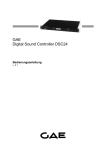
GAE
Digital Sound Controller DSC24
User‘s Manual
v. 3.1
Reference to EC statement of conformity
This document confirms that the product GAE Digital Sound Controller DSC24 bearing the CE label
meets all requirements in the EMC directive 89/336/EEC laid down by the Member States Counsel for
adjustment of legal requirements. Further more the product complies to the rules and regulations of
the electromagnetic compatibility of devices and electrical safety.
This product bearing the CE label complies with the following harmonised or national standards:
EN55013-1 (1996); EN55103-2 (1996); EN60065 (1993) IEC65 (1993) and amendments 1, 2 and 3
This product is also in accordance with:
73/23/EEC (Low Voltage Directive); 89/336/EEC (EMC Directive)
The product has been developed and manufactured in the European Union.
The authorised declaration and compatibility certification lies with the manufacturer and can be viewed
on request.
The awarding of the CE label confirms the compliance with legal directives issued for the manufacture
and marketing of electronic and electrical devices. As such the CE label is not a "seal of quality" but
rather proof that the device bearing the CE label is conform with the electromagnetic compatibility
standards laid down in the above named testing regulations.
Liability- and guarantee conditions
Declaration of liability. opal audio vertrieb GmbH accepts no liability for damage to loudspeakers,
amplifiers or other devices that become damaged through the use of the DSC24. This applies to the
regular, as well as the improper or negligent start-up and/or installation of the DSC24. Also, opal audio
vertrieb GmbH accepts no claims in tort, even from third parties, based on speculations of alleged
restricted or absence of function of the DSC24 (e.g. cancellation of events).
Product guarantee. Beyond the framework of the legal requirement, opal audio vertrieb GmbH
guarantees the DSC24 to be free from defects in material and workmanship for a period of 24 months
after date of purchase. As valid evidence for the beginning of the period of guarantee is the date of an
official GAE-distributor's issued invoice. As manufacturer, opal audio vertrieb GmbH will replace faulty
parts and restore defect modules within the period of guarantee, if the defect has appeared under
normal operating conditions. The evaluation of a guarantee claim is acknowledged after our
inspection, provided that the device has been returned freight and carriage paid and in the original
packaging. Excluded from guarantee are faults incurred by improper electrical or mechanical
connection or as a result of transport or accident. This guarantee is voided by any unauthorised repair
attempts or by the removal or alteration of the device's serial number.
Contents of packaging
The standard packaging of the DSC24 contains:
•
•
•
•
•
1 GAE Digital Sound Controller DSC24
1 approx. 1.5m serial connection cable, Sub-D9, for the connection to a serial PC-interface (COM)
1 IEC mains cable
Packaging elements, PE-cover
CD/floppy disk containing controller software and user manual's
Introduction
The digital signal controller DSC24 is a modern loudspeaker system controller designed for a
maximum of operational safety. 2 Inputs and 4 Outputs enable its use in 2-way stereo operation or for
the driving of 3 to 4-way combinations in mono operation. A system data-base for GAE loudspeaker
configurations with all relevant system parameters is available for simple download to the device.
Furthermore, the DSC24 offers totally unrestricted system configuration possibilities by means of the
Microsoft-Windows software supplied with the device.
Functions and characteristics of the DSC24:
•
•
•
•
•
•
•
•
High resolution 24-bit converters with 96kHz sampling frequency.
Digital Input with sample rate converter.
Mathematical standard filters with up to 48dB/octave, or in custom-mode, free filter parameter
th
definition up to 8 order.
Internal summing of inputs A & B forming a third input signal.
Input delay stage with six parametric EQ’s for individual tonal definition.
Precise limiter function, with gain and noise gate features for each output.
Each output combined with six, system correctional parametric EQ’s and a delay stage for runtime adjustments of each loudspeaker.
Import of measurement-data (ASCII) for complex equalisation of the connected loudspeaker
systems.
The following are just some of the operations possible with the DSC24:
•
3- or 4-way PA mono processor
•
3-way PA mono processor with sub-bass output through Aux. send
•
2-way stereo processor
•
2-way stereo processor with mono sub-bass + Aux.
•
4-output distribution system
•
Stereo parametric equaliser
•
Stereo delay line with EQ
•
Stereo compressor/limiter
®
The editing software (for Windows 95/98/NT/2000/Me/XP) supplied with the unit is specifically
designed for the modification of all parameters of the controller. Please study the software instruction
manual carefully before attempting to alter or build set-up configurations.
This manual explains the functions and the performance of the DSC24 device.
Before the initial start-up of the device, please read the following indications and warnings:
• Read the User's Guide carefully. It contains numerous pointers for the proper use of the device.
• It cannot be excluded, that this user's guide shows typographical failings or misprints, it is however
regularly checked and proof corrections can be requested in the form of future updates.
• Modifications which serve the purpose of technical improvement of the device may be carried out
without prior notification.
• Keep the original packaging of your DSC24, so that, in the case of returning the device for
maintenance, it can be shipped originally packed. We reserve the right to replace non-original
packaging on returning the device to the owner. In this case the packaging will be invoiced to the
customer.
• Always pay attention to the sufficient cooling of the device during operation. This especially applies
when installing in racks above other heat generating devices.
• Never pull the mains plug by means of the mains cable. Always pull the plug itself. Be certain, that
the mains cable does not become crushed or damaged by sharp edges and never replace a
damaged mains cable yourself.
• During operation and storage always protect the device from dust, moisture and direct sunlight.
• Only clean the device with a dry linen cloth. In the case of strong soiling this can be moistened with
water and a small amount of household detergent. Never use cleaning-agents containing solvents
to clean the device.
• Use only high-quality cable material to connect the device.
• Leave all repair- and maintenance-work to qualified technical personnel. Any future guarantee
claims will be invalidated by unauthorised manipulation.
• The opening of the device is not required for operation as there are no user adjustable components
located within the casing. Solely to configure the Digital Input to receive signals either of the
S/PDIF- or the AES/EBU-format will necessitate the removal of the device cover. Never forget, to
disconnect from the mains before opening the cover.
• The device including the mains cable and -plug may not be altered or redressed. The operation
with an opened enclosure is not permitted.
• Always ensure the correct grounding of the device via the mains-plug. Never cover the grounding
terminal of the plug by means of insulation material!
• Mains fuses cannot prevent an unexpected malfunction of electrical components, rather they
should protect the user and its environment from damage. For this reason never try to substitute
the mains fuse by any other than the specified M1A type (1A, medium behaviour). Never try to
repair or bypass a blown mains fuse.
• High sound pressure levels can lead to irreparable injures to the human hearing. In the region of
the threshold of pain even physical impairment of the entire organism cannot be exempted. Modern
sound systems are designed for high sound reproduction levels and as such, when improperly
handled, can cause injury to the human hearing organs. Never expose anybody, not even yourself,
to extreme high volume levels over a longer period of time.
DSC24 front panel
DIGITAL SIGNAL CONTROLLER DSC24
INPUT
A
UP
B
1
2
OUTPUT
CLIP
LIMIT
4dBu
-3dB
SIGNAL
3
4
SIGNAL
ENTER
DOWN
Input Signal LEDs
Green LED indicates signal present at the inputs.
2nd Green LED indicates signal = 4dBu.
Red LED indicates that the corresponding AD converter is in clip.
Navigation Keys
UP button allows navigation through the menus.
DOWN button allows navigation through the menus.
ENTER button allows access to the menus and sub-menus and is for confirming actions.
Output Signal LEDs
Green LED indicates signal present at output.
nd
2 Green LED indicates signal is 3dB below the Limiter threshold.
Red Led indicates that the C.R.I. Dynamics Control function is in operation.
DSC24 rear panel
OUTPUTS
ANALOG
INPUTS
A
B
RS-232C
MAINS INPUT
85 - 264V 50-60 Hz
1
2
3
4
AES/EBU IN
M 1A
PRIMARY
FUSE
Signal Inputs
Female XLR connectors (pin 2 hot).
Signal Outputs
Male XLR connectors (pin 2 hot).
RS-232C Connector
Female sub-D9 connector for PC communication via RS232C interface.
Digital Input
Female XLR digital input AES/EBU 32kHz - 96kHz (Internally configurable for S/PDIF)
Power Supply IEC Connector
The power cord is supplied together with the unit. The DSC24 includes a precise switching
power supply which operates with a mains supply from 85 to 264 volts and is continuously
self-regulating providing perfect functionality even with poorly regulated voltages.
Main Fuse
External 1A fuse access and spare fuse. Mains fuses cannot prevent an unexpected
malfunction of electrical components, rather they should protect the user and its environment
from damage. For this reason never try to substitute the mains fuse by any other than the
specified M1A type (1A, medium slow behaviour). Never try to repair or bypass a blown mains
fuse.
Overview
DSC24 Block Diagram
DA Converter
01011
10100
MEMORY 1
BUFFER
OUTPUT
1
BUFFER
OUTPUT
2
MEMORY 2
AD Converter
01011
10100
BUFFER
DA Converter
DSP1
01011
10100
DSP2
ON / OFF
RELAY
INPUT
A
AD Converter
INPUT
B
01011
10100
BUFFER
DA Converter
01011
10100
MICROCONTROLLER
BUFFER
OUTPUT
3
BUFFER
OUTPUT
4
DIGITAL AUDIO
RECEIVER
DIGITAL
INPUT
01011
10100
01011
10100
DA Converter
RS232-C
FLASH
MEMORY
FRONT
PANEL
01011
10100
DSP Block Diagram
A
ROUTER
CROSSOVER
PEQX
DELAY
A+B
DELAY
INPUT
A
A
DELAY
ROUTER
CROSSOVER
PEQX
DELAY
DYNAMIC
GATE
OUTPUT
2
GAIN
B
PEQ A+B
A+B
GAIN
A
ROUTER
CROSSOVER
PEQX
DELAY
A+B
DELAY
GAIN
OUTPUT
1
A
A+B
INPUT
B
GATE
B
PEQ A
GAIN
+
DYNAMIC
GAIN
DYNAMIC
GATE
OUTPUT
3
GAIN
B
PEQ B
B
A
A+B
ROUTER
CROSSOVER
PEQX
DELAY
DYNAMIC
GATE
GAIN
B
GAIN: Gain control. The DSC24 features two gain controls. The gain adjustable at the inputs
regulates the signal level received from the signal source. The output gain adjusts the level supplied to
each output.
DELAY: Configurable delay. Two delay stages are available. At the input stage delays of up to
300ms/100m are available for system delay purposes such as delay towers etc. The delay stage in
each of the channels is available for time-alignment purposes in the region up to 10ms /3.5m.
PEQ: Global input equalisation. Each input stage is provided with 6 user-configurable filters. These
can be of the parametric, low shelving (6dB/oct or 12dB/oct), high shelving (6dB/oct or 12dB/oct),
st
nd
highpass (12 dB/oct), lowpass (12 dB/oct), bandpass, reject band and 1 and 2 order allpass types.
CROSSOVER: Band separating filters. Filters available are: Linkwitz-Riley, Butterworth, Bessel and
th
Custom (with adjustable crossover frequencies, Q and slope up to 8 order). It is also possible to bypass a filter without affecting the subsequent band in order to create a full-bandwidth output.
PEQX: Independent output equalisation. 6 filters per output with the same features as for PEQ.
DYNAMIC: Specially designed, independent C.R.I. (Continuous Ratio Increment) dynamic curves are
included in each output channel of the DSC24 Processor. The dynamic curves work with a ratio
depending on the signal level, the relation 1:1 becoming progressively :1 as the signal level
increases. The resulting dynamic control is gradual and totally transparent offering much more
headroom than traditional limiters and can maintain the tonal balance between different channels
more effectively. Attack and Release time-constants are adjustable, with an automatic option.
OUTPUT
4
One of the great advantages of the multi-channel dynamic control is the elimination of the typical
pumping effect occurring when the limitation of some channels does not have control over the others.
The Limit control LEDs on the front panel are ON when the dynamic control is working. A blinking LED
does not mean that the channels limit has been reached when using CRI curves. Input level can be
increased until the Limit LEDs spend approximately the same time on as off. A continuous lighting of
the LEDs is to be avoided as audible tonal forfeits and a considerable loss of dynamics can be
expected from the continual overloading. In this situation, although protected by the limiter, the
loudspeaker components experience a considerable loading which can significantly shorten their life
expectancy.
GATE: Independent noise gate per output. These noise gates have been designed to provide a
gradual switch-off and an instantaneous switching on within the adjustable time parameters.
Operating Instructions
Preliminary Set-up
Connect your source device to the controllers inputs. Connect the controllers outputs to the inputs of
the systems power amplifiers. Connect the controller to the mains voltage. The unit operates safely
within a range of 85V...265V and 50Hz...400Hz. After a short boot and self-test process lasting around
10 seconds the device loads the last used preset, releases the protective mute to the four outputs and
is ready for operation. At initial set-up make sure that you only operate your system at low nominal
signal levels doubly-checking the correct speaker / power-amp link-up of the particular channels.
S/PDIF Digital Input
It is possible to configure the Digital Input to receive signals of the S/PDIF format. To do this carry out
the following steps:
Disconnect unit from the mains.
Open the lid of the enclosure.
On PCB C04-050 place jumpers J29 and J30 to change impedance to 75 and accept unbalanced
signals.
Use XLR input connector wired Pins 1 and 3 - Ground and Pin 2 - S/PDIF signal.
To return to AES/EBU format simply remove the jumpers J29 and J30.
Front Panel Displays and Function Keys
To enable the programming of some of the functions of the DSC24 the unit is equipped with a 2 line,
16-character LCD-Display and 3 function keys. 2 groups of LED bar-graphs indicate the status of the
DSC24's operation.
The three function keys UP, DOWN and ENTER enable the stepping through, the selection and the
confirmation of events within the unit's accessible menu's.
Menus
The configuration menus available from the unit's front panel are split into three distinct groups:
1. CONFIGURATION
2. INFORMATION
3. COMMUNICATION
The sub-menus of each of these groups allow access and easy configuration of the unit's available
parameters. Further configuration parameters are only accessible via the supplied
configuration-software.
On connecting the unit with the mains power supply the LCD-Display shows a welcoming message.
During this time the unit is in a warm-up and self-test process allowing the DSPs to achieve a stable
working temperature. On completion of this phase the DSPs are loaded with the last used program
from the unit's memory and is ready for operation. The LCD-Display shows in the first line the program
number and name. The second line shows the version number of the internal microprocessor
software.
The letter A or D in the top right-hand corner of the program-window indicates the selected input
signal: Analog or Digital.
From this position the selection of each of the unit's 19 memory locations is accessible. To select a
new set-up from the unit's memory simply step through the memory listing using the UP and DOWN
keys. On finding the memory required, depress and hold the ENTER key until the progress bar in the
display reaches the right hand side. This takes about 3 seconds and is intended as a safety precaution
against inadvertently loading a new program to the DSPs.
Access to the menu groups is achieved by the one-time pressing of the ENTER key in the programwindow.
Each of the three menu groups can be selected using the UP and DOWN keys.
Menu Group CONFIGURATION
The CONFIGURATION menu group is the main set of sub-groups for the front-panel configuration
possibilities of the 19 available memory locations.
Repeated pressing of the DOWN key enables access to each of the available sub-menus. Repeated
pressing of the ENTER key in a sub-menu provides access to each of the configurable parameters
within the chosen sub-menu. Pressing the ENTER key at the end of the list of available parameters
returns the display to the sub-menu listing. Only the available parameters for each set-up and submenu will be shown in the list of parameters.
Should no user activity be registered in a menu-group or a sub-menu for a period of about 12 seconds
the unit will automatically return to the program-window displaying the current set-up loaded to the
DSPs. This is to prevent the inadvertent changing of parameters during normal operation.
Menu Group CONFIGURATION - Sub-menus
Sub-menu 1.1 In Delay>ms
Here it is possible to determine the input delay for each input. (N.B. If the inputs and outputs of a setup have been renamed via the software then these names will be shown in each step of the relevant
sub-menu.) Delay values can be 0 - 300ms in 1ms increments or 0 - 100m in 1m increments.
1.1 In Delay>ms
InA : 0 ms
In B : 0 ms
A+B : 0 ms
Sub-menu 1.2 Out Delay>ms
Here it is possible to determine the delay time of each of the 4 output channels.
Delay values can be 0 - 10ms in 0.01ms increments or 0 - 3.6m in 0.01m increments.
1.2 Out Delay>ms
Out1 : 0 ms
Out 2 : 0 ms
Out 3 : 0 ms
Out 4 : 0 ms
Sub-menu 1.3 Input Gain
This window allows the setting of the individual gain for each input channel.
Gain values can be Mute, –40dB to +10db in 0.1dB increments.
1.3 Input Gain
InA : 00.0dB
In B : 00.0dB
A+B : –06.0dB
Sub-menu 1.4 Output Gain
From here it is possible to determine the output gain for each of the 4 output channels.
Gain values can be Mute, –40dB to +10db in 0.1dB increments.
1.4 Output Gain
Out1 : 00.0dB
Out 2 : 00.0dB
Out 3 : 00.0dB
Out 4 : 00.0dB
Sub-menu 1.5 Output Route
Here it is possible to determine which input signal is routed to which output.
Routing possibilities are Input A, Input B or Input A+B.
1.5 Output Route
Out1 : Input A
Out 2 : Input A
Out 3 : Input A
Out 4 : Input A
Sub-menu 1.6 MUTE Outputs
With this menu it is possible to turn each output on or off.
[X] = Output OFF, [ ] = Output ON.
1.6 MUTE Outputs
Out1 : [X]
Out 2 : [X]
Out 3 : [X]
Out 4 : [X]
Sub-menu 1.7 Output POL
In this window the polarity of the output signal can be determined.
Output POLarity can either be [+] (phase) or [–] (phase reverse).
1.7 Output POL
Out1 : [+]
Out 2 : [+]
Out 3 : [+]
Out 4 : [+]
Sub-menu 1.8 Program N
This menu allows the user to select a program from the unit's memory.
1.8 Program N:1
1. Name1
2. Name2
....
19. Name19
Sub-menu 1.9 Input Select
This menu selects which signal type is to be input to the processor.
1.9 Input Select
A Analog Input
D Digital Input
Sub-menu 1.10 Delay units
With this menu it is possible to determine the units for the delay functions
1.10 Delay units
milliseconds
Delay units
Meters
Sub-menu 1.11 Password
This menu allows the setting of a Password for the protection of the stored memories and against
unauthorised re-configuration.
1.11 Password OFF
Back Password: New Password:
*****
*****
Password ON
Sub-menu 1.12 Protect
Here it is possible to protect individual programs in the units memory from being overwritten with new
data.
1.12 Protect
1. Name1
Are you sure? [E]
1. Name1
Are you sure? [E]
1. Name1
Sub-menu 1.13 Calibrate
Here it is possible to force a new calibration of the A/D and D/A converters. This process optimises the
performance of the converters to achieve maximum sound quality
1.13 Calibrate
Calibrating......
Menu Group INFORMATION
The menu-group INFORMATION provides information about the version of the unit's DSPs and the unit's
memory.
Menu Group INFORMATION - Sub-menus
Sub-menu 2.1 DSP Version
Here the current version of the DSP software is indicated. It is possible to update the unit's DSP
Operating System software with the PC software supplied with the unit.
2.1 DSP Version
DSPs v3.10
Sub-menu 2.2 Prot. Memories
The number of memories which are in protect mode (1.12) are shown in this menu.
2.2 Prot. Memories
6 Protected
Menu Group COMMUNICATION
The menu group COMMUNICATION provides access to the parameters available for the communication
between two units. This method is referred to as cloning and enables an exact copy of the information
stored in the first processor (the configurations stored in the memory and the DSP Operating System
software version) to be cloned to the second processor.
Menu Group COMMUNICATION - Sub-menus
Sub-menu 3.1 Prepare Clon
Here it is possible to prepare the DSC24 to receive information from another unit and to become a
clone of that unit.
3.1 Prepare Clon
Prepare to CLON
Waiting for data
Receiving Data xx% Program Name A
Sub-menu 3.2 Clone
Here it is possible to prepare the DSC24 to send information to another unit to become a clone of this
unit.
3.1 Clone
Prepare to CLON
Press E to Start
Sending Data xx%
Program Name A
Sub-menu 3.3 Send Memory
Here it is possible to transmit the memory information of this DSC24 to that of a second unit.
3.1 Send Memory
Memory: 1
Prepare to SEND
Press E to Start
Sending Data xx%
Program Name A
Sub-menu 3.4 Receive Memo
Here it is possible to prepare the DSC24 to receive memory information from another unit.
3.1 Receive Memo
Memory: 1
Prepare to CLON
Waiting for data
Receiving Data xx% Program Name A
Sub-menu 3.5 Update OS
In this sub-menu the Operating System of the micro-controller can be updated to a new version.
For this process the user must use a special software provided by the manufacturer which contains
the new OS software. The message "Updating system” appears automatically when the controller
starts to receive date from the computer.
3.5 Update OS
Update OS
Updating system
WARNING!
The Update OS process is a dedicated process that could render the controller useless should it not
be permitted to finish.
Once the process has started it is imperative that it continues to the end.
This process lasts about five minutes. On completion of the data transfer the controller performs an
initialisation process and returns to the program window.
Technical Specifications
Analog Input
Input impedance.......................................................40kΩ, balanced
Connector.................................................................XLR balanced
AD Converter ...........................................................24bit - 96kHz, 128x Oversampling
Maximum input level ................................................18dBu
CMRR.......................................................................≥ 50dB
Crosstalk ..................................................................≤ –90dB
Radio frequency filter to avoid interference
Digital Input
Input impedance.......................................................110Ω
Connector.................................................................XLR balanced
Formats ....................................................................AES3, IEC 60985, EIAJ 1201, S/PDIF(jumpers)
Frequencies .............................................................96, 88.2, 48, 44.1, 32kHz with autodetection
Clock recovery .........................................................Internal via PLL
Output
Output impedance....................................................20Ω, balanced
Connector.................................................................XLR balanced
DA Converter ...........................................................24bit - 96kHz, 128x Oversampling
Maximum output level ..............................................18dBu
Drive capability.........................................................≥ 600Ω
Level loss .................................................................–0.3dB, into a load of 600Ω
Output asymmetry rejection .....................................≥ 56dB @ 1kHz; ≥ 52dB @16kHz
Distortion
THD+N ...........................................≤ 0.003% @ -1dBFS
DIM100 ...........................................≤ –90dB
Noise
@ 20Hz..20kHz ..............................≤ –96dBu unweighted
Basic delay
AD / DA...........................................0.72ms, without any filters
Remote input............................................................RS232 via SubD9female
Digital signal processing ........... Two 32-bit floating point DSPs with 40-bit of internal resolution
Memory capability ..................... 19 Set-ups
Power supply............................. 85...265VAC, 50...400Hz, Consumption ≤ 20W
Dimensions (H X W X D) .......... 1RU / 19” / 275mm
Weight ....................................... 3.5kg