1
Operating Instructions
Preliminary Set-up
Connect your source device to the controllers inputs. Connect the controllers outputs to the inputs of
the systems power amplifiers. Connect the controller to the mains voltage. The unit operates safely
within a range of 85V...265V and 50Hz...400Hz. After a short boot and self-test process lasting around
10 seconds the device loads the last used preset, releases the protective mute to the four outputs and
is ready for operation. At initial set-up make sure that you only operate your system at low nominal
signal levels doubly-checking the correct speaker / power-amp link-up of the particular channels.
S/PDIF Digital Input
It is possible to configure the Digital Input to receive signals of the S/PDIF format. To do this carry out
the following steps:
Disconnect unit from the mains.
Open the lid of the enclosure.
On PCB C04-050 place jumpers J29 and J30 to change impedance to 75 and accept unbalanced
signals.
Use XLR input connector wired Pins 1 and 3 - Ground and Pin 2 - S/PDIF signal.
To return to AES/EBU format simply remove the jumpers J29 and J30.
Front Panel Displays and Function Keys
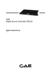
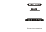
To enable the programming of some of the functions of the DSC24 the unit is equipped with a 2 line,
16-character LCD-Display and 3 function keys. 2 groups of LED bar-graphs indicate the status of the
DSC24's operation.
The three function keys UP, DOWN and ENTER enable the stepping through, the selection and the
confirmation of events within the unit's accessible menu's.
Menus
The configuration menus available from the unit's front panel are split into three distinct groups:
1. CONFIGURATION
2. INFORMATION
3. COMMUNICATION
The sub-menus of each of these groups allow access and easy configuration of the unit's available
parameters. Further configuration parameters are only accessible via the supplied
configuration-software.
On connecting the unit with the mains power supply the LCD-Display shows a welcoming message.
During this time the unit is in a warm-up and self-test process allowing the DSPs to achieve a stable
working temperature. On completion of this phase the DSPs are loaded with the last used program
from the unit's memory and is ready for operation. The LCD-Display shows in the first line the program
number and name. The second line shows the version number of the internal microprocessor
software.
The letter A or D in the top right-hand corner of the program-window indicates the selected input
signal: Analog or Digital.
From this position the selection of each of the unit's 19 memory locations is accessible. To select a
new set-up from the unit's memory simply step through the memory listing using the UP and DOWN
keys. On finding the memory required, depress and hold the ENTER key until the progress bar in the
display reaches the right hand side. This takes about 3 seconds and is intended as a safety precaution
against inadvertently loading a new program to the DSPs.