1
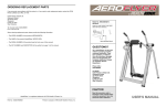
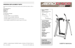
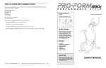
ORDERING REPLACEMENT PARTS
™
If you encounter any difficulties or problems with this product, contact the ICON Fitness Lifestyle Ltd. office, or
write:
ICON Fitness Lifestyle Ltd.
Greenwich House
223 North Street
Sheepscar
Leeds LS7 2AA
West Yorkshire, England
Model No. PFMC77753
Serial No.
Write the serial number in the space
above for reference.
Tel: Country Code: 0345-089009
Fax: 01789-440-798
To help us assist you, please be prepared to give the following information:
• The MODEL NUMBER of the product (PFMC77753).
• The NAME of the product (PROFORM® AIR WALKER).
• The SERIAL NUMBER of the product (see the front cover of this manual).
Serial Number Decal (under console)
• The KEY NUMBER and DESCRIPTION of the part(s) (see the PART LIST on page 10 of this manual).
QUESTIONS?
As a manufacturer, we are committed to providing complete
customer satisfaction. If you have
questions, or find that there are
missing or damaged parts, we will
guarantee you complete satisfaction through our Customer
Service Department.
Please CALL:
0345-089009
Or WRITE:
ICON Fitness Lifestyle Ltd.
Greenwich House
223 North Street
Sheepscar
Leeds LS7 2AA
West Yorkshire, England
CAUTION
Read all precautions and instructions in this manual before using
this equipment. Save this manual
for future reference.
Part No. 130348 R0996A © 1996 PROFORM is a registered treadmark of ICON Health & Fitness, Inc.
Printed in USA
USER'S MANUAL
TABLE OF CONTENTS
EXPLODED DRAWING—Model No. PFMC77753
IMPORTANT PRECAUTIONS . . . . . . . . . . . . . . . . . . . . . . . . . . . . . . . . . . . . . . . . . . . . . . . . . . . . . . . . . . . . .2
BEFORE YOU BEGIN . . . . . . . . . . . . . . . . . . . . . . . . . . . . . . . . . . . . . . . . . . . . . . . . . . . . . . . . . . . . . . . . . . .3
ASSEMBLY . . . . . . . . . . . . . . . . . . . . . . . . . . . . . . . . . . . . . . . . . . . . . . . . . . . . . . . . . . . . . . . . . . . . . . . . . . .4
HOW TO USE THE AIR WALKER . . . . . . . . . . . . . . . . . . . . . . . . . . . . . . . . . . . . . . . . . . . . . . . . . . . . . . . . . .7
MAINTENANCE AND TROUBLE-SHOOTING . . . . . . . . . . . . . . . . . . . . . . . . . . . . . . . . . . . . . . . . . . . . . . . . .8
CONDITIONING GUIDELINES . . . . . . . . . . . . . . . . . . . . . . . . . . . . . . . . . . . . . . . . . . . . . . . . . . . . . . . . . . . . .9
PART LIST . . . . . . . . . . . . . . . . . . . . . . . . . . . . . . . . . . . . . . . . . . . . . . . . . . . . . . . . . . . . . . . . . . . . . . . . . . .10
EXPLODED DRAWING . . . . . . . . . . . . . . . . . . . . . . . . . . . . . . . . . . . . . . . . . . . . . . . . . . . . . . . . . . . . . . . . .11
ORDERING REPLACEMENT PARTS . . . . . . . . . . . . . . . . . . . . . . . . . . . . . . . . . . . . . . . . . . . . . . . .Back Cover
39
54
48
51
49
42
44
50
14
40
5
33
13
12
47
21
20
36
57
41
19
2
24
22
27
53
56
13
21
47
25
23
12
36
27
26
47
15
17
45
55 12
46
41
27
16
55
38
38
10
10. When you are getting onto and off the AIR
WALKER, always tighten the resistance
knobs, hold the handles firmly, and be sure
that your body weight is centred directly over
the pedals.
3. Use the AIR WALKER only on a level surface.
Cover the floor beneath the AIR WALKER to
protect the floor or carpet.
15
47
58
2. Read all instructions in this manual before
using the AIR WALKER.
18
36
8
9. Do not wear loose clothing that could
become caught on the AIR WALKER. Always
wear athletic shoes for foot protection when
exercising.
46
12
57
34
35
32
WARNING: To reduce the risk of serious injury, read the following important precautions before
using the AIR WALKER.
1. It is the responsibility of the owner to ensure
that all users of the AIR WALKER are adequately informed of all warnings and precautions.
56
36
43
50
45
17
58
9
52
35
IMPORTANT PRECAUTIONS
R0996A
14
25
11
16
4
18
24
24
26
7
42
28
27
28
3
11. Use the AIR WALKER only as described in
this manual.
4. Be sure that there are no obstacles in front of
or behind the AIR WALKER.
12. If you feel faint, dizzy, or short of breath
whilst exercising, stop immediately and begin
cooling down.
5. Inspect and tighten all parts regularly.
Replace any worn parts immediately.
6. Keep small children and pets away from the
AIR WALKER at all times.
36
6
13. The following precautions are printed on the
electronic monitor: Read User’s Manual
before operating; To enter and exit, tighten
resistance knobs, grasp handles, and place
body directly over foot pedals; Stop if you
feel faint, dizzy, or short of breath; Keep children away.
7. The AIR WALKER should not be used by persons weighing more than 250 pounds (113
kg).
1
24
37
31
53
36
37
12
WARNING: Before beginning this or any exercise program, consult your physician. This is especially
important for persons over the age of 35 or persons with pre-existing health problems. Read all
instructions before using. ICON assumes no responsibility for personal injury or property damage
sustained by or through the use of this product.
53
53
37
30
31
31
2
29
37
8. Keep hands and feet away from moving parts.
53
29
11
12
30
31
PART LIST—Model No. PFMC77753
Key No.
Qty.
1
2
3
4
5
6
7
8
9
10
11
12
13
14
15
16
17
18
19
20
21
22
23
24
25
26
27
28
29
30
31
32
1
1
1
1
1
1
1
1
1
1
1
8
2
2
2
4
2
2
1
1
2
1
1
8
2
2
4
2
2
2
8
1
Description
Base
Top Frame w/Axle Caps
Left Upright
Right Upright
Rocker Arm w/Axle Caps
Left Leg
Right Leg
Left Link Arm w/Axle Caps
Right Link Arm w/Axle Caps
Left Handle w/Foam
Right Handle w/Foam
3/8” Nylon Jam Nut
Resistance Housing
Resistance Sleeve
Friction Cone
1/2” Thrust Washer
1/2” Thrust Bearing
1/2” Plastic Washer
Right Hub Cover
Right Pivot Bracket w/Axle Caps
Pivot Sleeve w/Axle Caps
Left Hub Cover
Left Pivot Bracket w/Axle Caps
3/8” x 1/2” Screw
2” Upper Screw
2 1/4” Lower Screw
3/8” Curved Washer
Pedal
3/8” x 1 3/4” Bolt
Wheel
#8 x 1/2” Screw
1/2” x 2” Bolt
R0996A
Key No.
Qty.
33
34
35
36
37
38
39
40
41
42
43
44
45
46
47
48
49
50
51
52
53
54*
55
56
57
58
#
#
2
1
2
6
4
2
1
1
2
2
1
1
2
2
6
1
2
2
1
1
6
1
2
2
2
2
1
1
Description
Pivot Bushing
1/2” Nylon Jam Nut
1” Plastic Washer
1 1/2” x 3” Endcap
Rubber Foot
#10 x 1/2” Metal Screw
Electronic Monitor
Console
Plastic Sleeve
Foam Grip
#8 x 3/8” Screw
Reed Switch w/Wire
Resistance Cover
Resistance Knob
3/8” x 2” Carriage Bolt
Magnet
#3 x 1/4” Screw
3/8” Lock Washer
Retainer
Magnetic Concentrator
#8 x 3/4” Metal Screw
Console Assembly
Retainer Ring
Link Arm Bushing w/Axle Caps
Dome Cap
Snap Ring
User’s Manual
Allen Wrench
BEFORE YOU BEGIN
Thank you for selecting the innovative PROFORM®
AIR WALKER. The AIR WALKER blends advanced
engineering with contemporary styling to offer you a
no-impact, total body workout in the convenience of
your own home.
please note the product model number and serial
number before calling. The model number is
PFMC77753. The serial number can be found on a
decal attached to the AIR WALKER (see the front
cover of this manual).
For your benefit, read this manual carefully before
using the PROFORM® AIR WALKER. If you have
additional questions, please call our Customer Service
Department at 0345-089009. To help us assist you,
Before reading further, please review the drawing
below and familiarise yourself with the parts that are
labelled.
Handles
Monitor
Console
Resistance Knobs
Uprights
* Includes all parts shown in the box.
# These parts are not illustrated.
Note: Specifications are subject to change without notice. See the back cover of this manual for information
about ordering replacement parts.
Legs
Pedals
LEFT SIDE
RIGHT SIDE
Base
Wheels
10
3
ASSEMBLY
CONDITIONING GUIDELINES
Before you begin assembly, carefully read the
following information and instructions:
• Read through each assembly step before you
begin.
• Place all parts of the AIR WALKER in a cleared
area and remove the packing materials.
IMPORTANT: DO NOT REMOVE THE RUBBER
BANDS FROM THE HUB COVERS (see
assembly step 5). Do not dispose of any
packing materials until assembly is completed.
• Make sure that all parts are oriented as shown in
the drawings. Tighten all parts as you assemble
them, unless instructed to do otherwise.
The following guidelines will help you to plan your
exercise program. Remember that proper nutrition and
adequate rest are essential for successful results.
listed according to age and physical condition.
During the first few months of your exercise program,
keep your heart rate near the low end of your training
zone as you exercise. After a few months of regular
exercise, your heart rate can be increased gradually
until it is near the middle of your training zone as you
exercise.
WARNING: Before beginning this or any exercise
program, consult your physician. This is especially important for individuals over the age of 35
or individuals with pre-existing health problems.
To measure your
heart rate, stop
exercising and
place two fingers
on your wrist. Take
a six-second
heartbeat count,
and multiply the
result by ten to
find your heart
rate. (A six-second
count is used because your heart rate drops quickly
when you stop exercising.) If your heart rate is too
high, decrease the intensity of your exercise. If your
heart rate is too low, increase the intensity of your
exercise.
Assembly requires the following tools:
• Use the drawings below to identify the small
hardware used in assembly.
• the included allen wrench
WHY EXERCISE?
• your own phillips screwdriver
Exercise has proven essential for good health and
general well-being. Regular participation in a wellrounded exercise program helps to develop a stronger
and more efficient heart, improved respiratory function,
increased stamina and endurance, better weight management and body fat control, increased ability to deal
with stress, and greater self-esteem and confidence.
2" Upper Screw (25)–2
3/8" x 1/2" Screw (24)–8
3/8" Curved Washer (27)–4
2 1/4" Lower Screw (26)–2
#8 x 1/2" Screw (31)–8
1. Before you begin, read the information at the
top of this page.
Fig. 1
“TOP RIGHT”
Sticker
“TOP LEFT”
Sticker
See figure 1. Find the Left Upright (3). Note:
There is a “TOP LEFT” sticker on the upper
end of the Left Upright.
EXERCISE INTENSITY
To maximize the benefits of exercising, it is important
to exercise with the proper intensity. The proper intensity level can be found by using your heart rate as a
guide. For effective aerobic exercise, your heart rate
should be maintained at a level between 70% and
85% of your maximum heart rate as you exercise.
This is known as your training zone. You can find your
training zone in the table below. Training zones are
WORKOUT GUIDELINES
A well-rounded workout includes the following three
phases:
A warm-up phase, lasting 5 to 10 minutes. Begin with
slow, controlled stretches, and progress to more rhythmic stretches. This will increase the body temperature,
heart rate, and circulation in preparation for strenuous
exercise.
TRAINING ZONE (BEATS/MIN.)
4
3
See figure 1. Slide the Left Upright (3) onto the
Base (1). Thread two 3/8” x 1/2” Screws (24) into
the Left Upright. Do not tighten the Screws yet.
24
See figure 1. Attach the Right Upright (4) in the
same manner.
1
2. See figure 2. Hold the Top Frame (2) level, and
insert it into the Left and Right Uprights (3 and 4).
Note: It may be helpful to rock the Top Frame
from side to side slightly as you insert it.
Make sure that the indicated rubber bands are
not pinched between the Top Frame and the
Uprights. Attach the Top Frame with four 3/8” x
1/2” Screws (24).
Fig. 2
2
Rubber
Band
See figures 1 and 2. Tighten the eight 3/8” x 1/2”
Screws (24).
AGE
Rubber
Band
24
4
24
UNCONDITIONED CONDITIONED
20
138–167
133–162
25
136–166
132–160
30
135–164
130–158
35
134–162
129–156
40
132–161
127–155
45
131–159
125–153
50
129–156
124–150
55
127–155
122–149
60
126–153
121–147
65
125–151
119–145
70
123–150
118–144
75
122–147
117–142
80
120–146
115–140
85
118–144
114–139
A cardiovascular phase, including 20 to 30 minutes
of exercising with your heart rate in your training zone.
A cool-down phase, consisting of 5 to 10 minutes of
stretching. Thorough stretching offsets muscle contractions and other problems caused when you stop
exercising suddenly. Stretching for increased flexibility
is often most effective during this phase. This phase
should leave you relaxed and comfortably tired.
To maintain or improve your condition, complete three
workouts each week, with at least one day of rest
between workouts. After a few months of regular exercise, you may complete up to five workouts each
week, if desired. Find the best time of day for your
workouts, and then stick with it.
Remember, the key to success is to make exercise a
regular and enjoyable part of your everyday life.
3
4
9
OPERATING THE ELECTRONIC MONITOR
Reps/min, reps, calories, or time mode—These
modes can be individually selected by repeatedly
pressing the mode button. The mode indicators
will show which mode has been selected. (Make
sure that the scan all mode is not selected.) The
modes will be selected in the following order:
reps/min, reps, calories, scan all, time.
1. To turn on the power, press the on/clear button or
simply begin exercising on the AIR WALKER. The
entire display will appear for two seconds. The
electronic monitor will then be ready for operation.
3. See figure 3b. Find the Right Leg (7). Note: The
Right Leg is marked with a “RIGHT” sticker.
Set a Pedal (28) on the plate at the lower end of
the Right Leg. Note: Be careful not to attach
the Pedal backwards. Look at the curve of the
Right Leg and the front end of the Pedal to
make sure that the Pedal is turned correctly.
Fig. 3a
Fig. 3b
2. Select one of the five modes:
3. The monitor has an auto-off feature to turn off
the power. If the pedals are not moved and the
monitor buttons are not pressed for four minutes,
the power will turn off automatically in order to
conserve the batteries.
Scan all mode—When the power is turned on, the
scan all mode will be selected automatically. The
scan all mode can also be selected by repeatedly
pressing the mode button. One mode indicator will
show that the scan all mode has been selected,
and a second mode indicator will show which
mode is currently displayed.
31
See figure 3a. Turn the Right Leg (7) and the
Pedal (28) upside-down as shown. Attach the
Pedal with four #8 x 1/2” Screws (31).
7
28
“RIGHT”
Sticker
Right Leg
curves in this
direction.
To reset the LCD display, press the on/clear button.
7
Front
End
MAINTENANCE AND TROUBLE-SHOOTING
28
MAINTENANCE
See figure 3. Make
sure that the reed
switch wire is plugged
into the monitor; insert
any excess wire into
the console. Snap the
monitor into the console. Make sure that
the wire is not pinched
between the monitor
and the console.
Inspect and tighten all parts of the AIR WALKER regularly. Replace any worn parts immediately.
The AIR WALKER can be cleaned with a soft, damp
cloth. Keep liquids away from the electronic monitor.
Keep the monitor out of direct sunlight or the display
may be damaged. Remove the batteries when storing
the AIR WALKER.
Fig. 3
Monitor
Console
See figure 2. If there
is a gap between
the positive (+) ends
of the batteries and
the metal contacts,
the monitor will not
turn on. Push the
batteries to make
sure that the positive ends are
touching the metal
contacts.
Fig. 1
Reed Switch Wire
Coin
Fig. 2
If the electronic monitor still does not function properly, the batteries should be replaced. Two “AA” batteries are required; alkaline batteries are recommended.
Remove the two old batteries from the monitor, and
insert two new batteries. Make sure that the negative (–) ends of the batteries are touching the
springs and that the positive (+) ends of the batteries are pushed against the metal contacts.
Console
Monitor
Fig. 4
“RIGHT”
Sticker
See figure 4. Find the Right Handle (11). Note:
The Right Handle is marked with a “RIGHT”
sticker. Insert the Right Handle into the Right
Leg (7).
ELECTRONIC MONITOR TROUBLE-SHOOTING
If the electronic
monitor will not turn
on, the batteries
should be checked.
Using a coin, pry up
the front of the
monitor and remove
it from the console
(see figure 1).
4. See figure 4. Look into the upper end of the
Right Leg (7) and make sure that the Plastic
Sleeve (41) is fully inserted.
11
See figure 4. Slide a 3/8” Curved Washer (27)
onto a 2” Upper Screw (25). Note: Use the
actual-size drawing to identify the 2” Upper
Screw (25). Insert the 2” Upper Screw into the
upper hole in the Right Leg (7) and the Right
Handle (11).
41
27
25
See figure 4. Slide a 3/8” Curved Washer (27)
onto a 2 1/4” Lower Screw (26). Note: Use the
actual-size drawing to identify the 2 1/4”
Lower Screw (26). Insert the 2 1/4” Lower
Screw into the lower hole in the Right Leg (7)
and the Right Handle (11).
26
Batteries
“RIGHT”
Sticker
2” Upper Screw (25)
See figure 4. Make sure that the 2” Upper
Screw (25) is in the upper hole and that the
2 1/4” Lower Screw (26) is in the lower hole.
The Screws must be inserted from the side
shown.
Metal Contact
7
2 1/4” Lower Screw (26)
Note: This step requires one 2” Upper Screw (25)
and one 2 1/4” Lower Screw (26). The 2” Upper
Screw (25) must be in the upper hole; the 2 1/4”
Lower Screw (26) must be in the lower hole.
Metal Contact
Back of Monitor
8
5
5. See figure 5a. Before you begin this step,
make sure that the Right Hub Cover (19) is
attached to the Top Frame (2) with a rubber
band as shown. If the Right Hub Cover has
come off during shipping, see figure 5b.
Slide the Right Hub Cover onto the Right
Pivot Bracket (20).
HOW TO USE THE AIR WALKER
Fig. 5a
2
Rubber Band
See figure 5a. Find the two holes inside the slot
of the Right Hub Cover (19). Make sure that the
rubber band is not covering the holes, and that
the holes are aligned.
Note: The 2” Upper
Screw (25) must
be tightened first.
Hole
19
7
“RIGHT”
Sticker
Repeat assembly steps 3, 4, and 5 to attach
the Left Leg and the Left Handle (not shown) to
the left side of the AIR WALKER.
Reps—Displays the total number of repetitions you
have completed, up to “999.” The display will then
reset to “0” and continue counting.
Calories—Displays the approximate number of calories you have burned. Note: If the resistance is near
the highest or lowest setting, the actual number of
calories you have burned will be slightly higher or
lower than the number displayed.
For a full body workout, hold the handles as you walk,
moving your arms and legs in motion with the handles
and pedals. To vary the effect on your muscles,
change your stance on the AIR WALKER. For example, you can change the position of your hands on the
handles, or you can bend your legs slightly instead of
keeping them straight.
Fig. 5b
See figure 5a. Fully tighten the 2” Upper Screw
(25). After the 2” Upper Screw is tightened, fully
tighten the 2 1/4” Lower Screw (26).
Reps/min—Displays the number of repetitions you
are performing per minute.
The proper form for exercising on the AIR WALKER
is similar to walking—move one leg forward as you
move the other leg back. Never attempt to move
both legs in the same direction—you could be
injured, or the AIR WALKER could be damaged.
Hole
26
The simple-to-operate electronic monitor offers
five different modes to provide instant exercise
feedback. The five modes are described below:
EXERCISING ON THE AIR WALKER
25
See figure 5a. Hold the Right Leg (7) against
the Right Hub Cover (19). Thread the 2” Upper
Screw (25) two complete turns into the upper
hole inside the Right Hub Cover. Thread the
2 1/4” Lower Screw (26) two complete turns
into the lower hole. Break and remove the rubber band.
ELECTRONIC MONITOR MODES
CAUTION: When you are getting onto and off
the AIR WALKER, always tighten the resistance knobs, hold the handles firmly, and be
sure that your body weight is centred directly
over the pedals.
20
Scan All—Displays the reps/min, reps, calories, and
time modes, for approximately 5 seconds each,
in a repeating cycle.
Time—Displays the length of time you have exercised. Note: If you stop exercising for ten seconds or
longer, the time mode will pause until you resume.
For a lower body workout, rest your hands on the
edge of the console for balance as you walk on the
pedals. Note: Do not lean on the console. It is not
designed to support your body weight.
19
DIAGRAM OF THE ELECTRONIC MONITOR
RESISTANCE ADJUSTMENT
To vary the intensity of your workout, the resistance of
the AIR WALKER can be changed. To increase the
resistance, turn both resistance knobs clockwise. To
decrease the resistance, turn the resistance knobs
counterclockwise.
6. See figure 6a. Insert two “AA” batteries (not included) into the Monitor (39). Alkaline batteries are
recommended. Make sure that the negative (–)
ends of the batteries are touching the springs,
and that the positive (+) ends of the batteries
are pushed against the metal contacts.
1
2
3
4
Fig. 6a
Batteries
39
40
Fig. 6b
See figure 6a. Plug the Reed Switch Wire (44)
into the Monitor (39). Insert any excess wire into
the Console (40).
40
39
44
1. LCD display—Displays all modes.
See figure 6b. Snap the Monitor (39) into the
Console (40). Be careful not to pinch the wire
between the Monitor and the Console.
2. Mode indicators—Show which mode has
been selected.
Resistance
Knobs
3. Mode button—Selects all modes.
Before you use the AIR WALKER, use the included allen wrench to firmly re-tighten all of the screws used in
assembly. Remove the orange and green identification stickers from the AIR WALKER. Note: During the first
few minutes that the AIR WALKER is used, a squeaking noise may be heard. This is normal during the
break-in period.
6
4. On/Clear button—Turns the power on and
resets all modes.
7