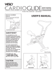
1
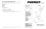
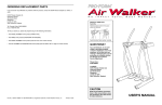
TM
ORDERING REPLACEMENT PARTS
If you encounter any difficulties or problems with this product, contact the ICON Fitness Lifestyle Ltd. office, or
write:
ICON Fitness Lifestyle Ltd.
Greenwich House
223 North Street
Sheepscar
Leeds LS7 2AA
West Yorkshire
Tel: Country Code: 0345-089009
Fax: 0113-2411120
Model No. WLCR28061
Serial No.
Write the serial number in the space
above for reference.
• The MODEL NUMBER of the product. (WLCR28061)
USER'S MANUAL
• The NAME of the product. (WESLO® CARDIOGLIDE TR 2)
• The SERIAL NUMBER of the product. (See the front cover of this manual.)
• The KEY NUMBER of the part(s) needed. (See page 10 of this manual.)
Serial Number Decal
• The DESCRIPTION of the part(s) needed. (See page 10 of this manual.)
QUESTIONS?
As a manufacturer, we are
committed to providing
complete customer satisfaction.
If you have questions, or find
that there are missing or
damaged parts, we will
guarantee you complete
satisfaction through our
Customer Service Department.
Please CALL:
0345-089009
Or WRITE:
ICON Fitness Lifestyle Ltd.
Greenwich House
223 North Street
Sheepscar
Leeds LS7 2AA
West Yorkshire
CAUTION
Read all precautions and instructions in this manual
before using this equipment.
Save this manual for future
reference.
Part No. 138098 R0997A
Weslo is a registered trademark of ICON Health & Fitness, Inc. © 1997 Printed in China
PUSH MODE
PULL MODE
TABLE OF CONTENTS
EXPLODED DRAWING—Model No. WLCR28061
IMPORTANT PRECAUTIONS . . . . . . . . . . . . . . . . . . . . . . . . . . . . . . . . . . . . . . . . . . . . . . . . . . . . . . . . . . . . . . . . .2
BEFORE YOU BEGIN . . . . . . . . . . . . . . . . . . . . . . . . . . . . . . . . . . . . . . . . . . . . . . . . . . . . . . . . . . . . . . . . . . . . . . .3
ASSEMBLY . . . . . . . . . . . . . . . . . . . . . . . . . . . . . . . . . . . . . . . . . . . . . . . . . . . . . . . . . . . . . . . . . . . . . . . . . . . . . . .4
HOW TO USE THE CARDIOGLIDE TR 2 . . . . . . . . . . . . . . . . . . . . . . . . . . . . . . . . . . . . . . . . . . . . . . . . . . . . . . . .5
MAINTENANCE AND TROUBLE-SHOOTING . . . . . . . . . . . . . . . . . . . . . . . . . . . . . . . . . . . . . . . . . . . . . . . . . . . .8
CONDITIONING GUIDELINES . . . . . . . . . . . . . . . . . . . . . . . . . . . . . . . . . . . . . . . . . . . . . . . . . . . . . . . . . . . . . . . .9
PART LIST . . . . . . . . . . . . . . . . . . . . . . . . . . . . . . . . . . . . . . . . . . . . . . . . . . . . . . . . . . . . . . . . . . . . . . . . . . . . . . .10
EXPLODED DRAWING . . . . . . . . . . . . . . . . . . . . . . . . . . . . . . . . . . . . . . . . . . . . . . . . . . . . . . . . . . . . . . . . . . . . .11
ORDERING REPLACEMENT PARTS . . . . . . . . . . . . . . . . . . . . . . . . . . . . . . . . . . . . . . . . . . . . . . . . . .Back Cover
R0997A
20
2
16
16
4
7
13
42
19
3
33
1
30
13
29
IMPORTANT PRECAUTIONS
45
34
WARNING: To reduce the risk of serious injury, read the following important precautions before
using the WESLO® CARDIOGLIDE TR 2.
29 43
40
25
41
35
42
21
15
37
35
1. It is the responsibility of the owner to ensure
that all users of the TR 2 are adequately
informed of all precautions.
8. Before exercising, make sure that the link
arms are securely connected to the upper or
lower rollers on the handlebar.
2. Use the TR 2 only on a level surface. Cover
the floor beneath the TR 2 for protection.
9. The resistance cylinder becomes very hot
during use. Allow the resistance cylinder to
cool before touching it. When adjusting the
resistance, touch only the resistance
adjustment collar.
3. The TR 2 should not be used by persons
weighing more than 250 pounds (115 kg).
4. Keep children under 12 and pets away from
the TR 2 at all times.
5. Wear appropriate clothing when exercising;
do not wear loose clothing that could become caught on the TR 2. Always wear
athletic shoes for foot protection.
6. Inspect and tighten all parts regularly.
Replace any worn parts immediately.
7. After adjusting the position of the seat, make
sure that the seat knob is firmly tightened.
10. Do not use the TR 2 when the resistance
cylinder is below room temperature or it may
be damaged.
5
40
22
43
36
38
29
29
14
11
25
8
44
39
6
41
15
18
29
8
29
29
8
26
28
29
40
31
23
30
32
22
11. Always keep your back straight when using
the TR 2; do not arch your back.
12. Use the TR 2 only as described in this
manual.
13. The TR 2 is intended for home use only. Do
not use the TR 2 in any commercial, rental,
or institutional setting.
24
12
9
27
23
29
17
12
24
8
40
10
30
WARNING: Before beginning this or any exercise program, consult your physician. This is
especially important for persons over the age of 35 or persons with pre-existing health problems.
Read all instructions before using. ICON assumes no responsibility for personal injury or property
damage sustained by or through the use of this product.
2
11
PART LIST—Model No. WLCR28061
Key
No.
Qty.
1
2
3
4
5
6
7
8
9
10
11
12
13
14
15
16
17
18
19
20
21
22
23
24
25
1
1
1
1
1
1
1
4
1
2
1
2
3
1
1
2
1
1
1
1
1
2
4
2
2
Description
Monitor
Handlebar
Seat
Left Link Arm
Seat Frame
Frame
Right Link Arm
Round Endcap
Resistance Cylinder
Pedal Frame Endcap
38mm x 50mm Endcap
Pedal
Link Arm Bushing
Bumper
Reed Switch/Sensor Wire
Handle Screw
Round Bumper
Reed Switch Screw
Centre Link Arm
Handle
9.5mm x 275mm Pivot Axle
12.7mm x 80mm Axle
12.7mm Cylinder Bushing
12.7mm x 23.5mm ABS Spacer
9.5mm Bushing
R0997A
Key
No.
Qty.
Description
26
27
28
29
30
31
32
33
34
35
36
37
38
39
40
41
42
43
44
45
#
#
1
1
1
11*
12*
1
1
4
1
2
1
1
1
1
4
4
2
2
1
1
1
1
Foam Pad
Magnet/Retainer
12.7mm x 146mm Axle
12.7mm Dome Cap
12.7mm Push Nut
12.7mm x 106mm Axle
Pedal Frame
Roller
Seat Bracket
Seat Bracket Screw
Washer
Clip
Seat Knob
12.7mm x 162mm Axle
12.7mm x 27mm Bushing
12.7mm Bushing
9.5mm Dome Cap
12.7mm Link Arm Spacer
12.7mm x 100mm Axle
Seat Bolt
User’s Manual
Pedal Tool
BEFORE YOU BEGIN
Thank you for selecting the WESLO® CARDIOGLIDE
TR 2. The CARDIOGLIDE TR 2 offers a unique form of
low-impact exercise that uses both the upper body and
the lower body for greater cardiovascular benefits and
increased toning. For a more complete workout, the
CARDIOGLIDE TR 2 features both a push mode and a
pull mode, and the adjustable resistance cylinder lets
you exercise at the intensity level that’s right for you.
For your benefit, read this manual carefully before
using the CARDIOGLIDE TR 2. If you have additional
questions, please call our Customer Service
Department at 0345-089009. To help us assist you,
please note the product model number and serial
number before calling. The model number is
WLCR28061. The serial number can be found on a
decal attached to the CARDIOGLIDE TR 2 (see the
front cover of this manual for the location of the decal).
Before reading further, please take a moment to
familiarise yourself with the parts that are labelled in
the drawing below.
Link Arms
Handlebar
Quick Adjust Handle
Rollers for Push Mode
Padded Seat
*Note: One extra 12.7mm Dome Cap and extra
12.7mm Push Nuts may have been included.
Note: “#” indicates a non-illustrated part. Specifications are subject to change without notice. See the back cover
of this manual for information about ordering replacement parts.
Monitor
Seat Knob
Rollers for Pull Mode
Resistance Cylinder
Pedal
10
3
ASSEMBLY
CONDITIONING GUIDELINES
Place all parts of the CARDIOGLIDE TR 2 in a cleared area and remove the packing materials. Do not dispose of
the packing materials until assembly is completed. Read each step carefully before you begin. Assembly
requires the following tools: The included pedal tool
, and your own rubber mallet
.
The following guidelines will help you to plan your
exercise program. Remember that proper nutrition and
adequate rest are essential for successful results.
1. Note: Before you attach the 9.5mm Dome Caps (42)
shown in this step, make sure that the Handlebar
(2) is turned as shown. If the Handlebar is
incorrectly attached, it will be necessary to remove
the Dome Caps and order new ones.
WARNING: Before beginning this or any exercise
program, consult your physician. This is especially
important for individuals over the age of 35 or
individuals with pre-existing health problems.
1
2
WHY EXERCISE?
42
Tap two 9.5mm Bushings (25) into the Frame (6) as
shown. Align the indicated holes in the Handlebar (2)
with the 9.5mm Bushings (25) in the Frame (6). Insert
the 9.5mm x 275mm Pivot Axle (21) through the
Handlebar and the Frame. Centre the Pivot Axle and
tap a 9.5mm Dome Cap (42) onto each end of it.
Holes
25
21
42
6
25
2. Hold the Handlebar (2) in the position shown. Hold the
Handle (20) and hook the Link Arms (4, 7) onto the
lower Rollers (33) on the Handlebar. Make sure that
the Link Arms are securely connected to the
Rollers.
2
EXERCISE INTENSITY
2
4
33
20
7
3. The Seat (3) is attached to the underside of the Seat
Frame (5) for shipping purposes. Remove the Seat
Knob (38) and the Washer (36) and remove the Seat
from the Seat Frame.
To maximise the benefits of exercising, it is important
to exercise with the proper intensity. The proper
intensity level can be found by using your heart rate
as a guide. For effective aerobic exercise, your heart
rate should be maintained at a level between 70% and
85% of your maximum heart rate as you exercise.
This is known as your training zone. You can find your
training zone in the table below. Training zones are
listed according to age and physical condition.
TRAINING ZONE (BEATS/MIN.)
3
AGE
45
UNCONDITIONED CONDITIONED
20
138–167
133–162
25
136–166
132–160
30
135–164
130–158
35
134–162
129–156
36
40
132–161
127–155
38
45
131–159
125–153
50
129–156
124–150
55
127–155
122–149
60
126–153
121–147
65
125–151
119–145
70
123–150
118–144
75
122–147
117–142
80
120–146
115–140
85
118–144
114–139
3
Insert the Seat Bolt (45), located under the Seat (3),
down into the slot in the Seat Frame (5). Thread the
Seat Knob (38), with the Washer (36), onto the Seat
Bolt. Slide the Seat to the desired position and firmly
tighten the Seat Knob.
4. The Monitor (1) requires two “AA” batteries (not
included). Alkaline batteries are recommended. Insert
two batteries into the battery compartment. Make sure
that the negative (–) ends of the batteries are
touching the springs in the battery compartment.
Exercise has proven essential for good health and
general well-being. Regular participation in a wellrounded exercise program results in a stronger and
more efficient heart, improved respiratory function,
increased stamina and endurance, better weight
management and body fat control, increased ability to
deal with stress, and greater self-esteem and
confidence.
5
4
Batteries
1
During the first few months of your exercise program,
keep your heart rate near the low end of your training
zone as you exercise. After a few months of regular
exercise, your heart rate can be increased gradually
until it is near the middle of your training zone as you
exercise.
To measure your
heart rate, stop
exercising and
place two fingers
on your wrist. Take
a six-second
heartbeat count
and multiply the
result by ten to find
your heart rate. (A
six-second count
is used because your heart rate will drop quickly when
you stop exercising.) If your heart rate is too high,
decrease the intensity of your exercise. If your heart
rate is too low, increase the intensity of your exercise.
WORKOUT GUIDELINES
Each workout should include the following three parts:
A warm-up, lasting 5 to 10 minutes. Begin with slow,
controlled stretches, and progress to more rhythmic
stretches. This will increase the body temperature,
heart rate, and circulation in preparation for strenuous
exercise.
A cardiovascular exercise period, consisting of 20 to
30 minutes of exercising with your heart rate in your
training zone.
A cool-down, with 5 to 10 minutes of stretching.
Thorough stretching offsets muscle contractions and
other problems caused when you stop exercising
suddenly. Stretching for increased flexibility is also
most effective after exercise. A proper cool-down
should leave you relaxed and comfortably tired.
EXERCISE FREQUENCY
To maintain or improve your condition, complete three
workouts each week, with at least one day of rest
between workouts. After a few months of regular
exercise, you may complete up to five workouts each
week, if desired. Find the best time of day for your
workouts, and then stick with it. Remember, the key to
success is to make exercise a regular and enjoyable
part of your everyday life.
Battery Compartment
4
9
5. Connect the Sensor Wire (15) to the wire on the Monitor
(1). Insert all excess wire into the Frame (6).
MAINTENANCE AND TROUBLE-SHOOTING
Inspect and tighten all parts of the CARDIOGLIDE TR 2 regularly. Make sure
that the Foam Pad (26) is pushed all of the way onto the axle at the front. The
CARDIOGLIDE TR 2 can be cleaned with a soft, damp cloth. Keep liquids away
from the monitor. Do not expose the monitor to direct sunlight or the display may
be damaged. When storing the CARDIOGLIDE TR 2, remove the batteries from
the monitor.
5
1
1
Hold the Monitor (1) with both hands, and slide it down
onto the Frame (6). Refer to the inset drawing. Make
sure that the side of the Monitor (1) is between the
Frame (6) and the 12.7mm Dome Cap (29). Push the
Dome Cap against the side of the Monitor.
26
29
Front View
39
15
26
Slide the Foam Pad (26) onto the end of the 12.7mm x
162mm Axle (39).
6
HOW TO REPLACE THE BATTERIES
If the display of the Monitor (1) becomes dim, the two “AA”
batteries should be replaced. Lift the Monitor off the Frame
(6). Disconnect the Sensor Wire (15) from the Monitor. Make
sure that the end of the Sensor Wire does not slip into
the Frame. Remove the two old batteries from the Monitor.
Insert two new batteries. Make sure that the negative (–)
ends of the batteries are touching the springs in the
Monitor.
6. Lightly grease the shaft on the right side of the Pedal
Frame (32). Slide a Pedal (12) onto the shaft. Make sure
that the plastic tube on the Pedal is facing the Pedal
Frame. Using the included pedal tool, tap a 12.7mm
Push Nut (30) onto the shaft. Make sure that the Push
Nut is turned as shown in the inset drawing. Attach
another 12.7mm Push Nut (30) in the same manner.
1
Batteries
6
32
Plastic
Tube
Attach the other Pedal (not shown) in the same manner.
15
Connect the Sensor Wire (15) to the wire on the Monitor (1).
Insert all excess wire into the Frame (6). Press the
Monitor onto the Frame (see assembly step 5 on page 5).
6
1
Apply
Grease
Note: Extra 12.7mm Push Nuts (30) may have been
included. Save the Push Nuts and the pedal tool in case
replacement Push Nuts are needed in the future.
32
Clip
Teeth
12
30
Note: The CARDIOGLIDE TR 2 features a precision
resistance cylinder; due to the nature of resistance
cylinders, a mat should be placed under the
CARDIOGLIDE TR 2 in case of slight oil leakage.
HOW TO ADJUST THE MAGNET AND REED SWITCH
If the monitor displays incorrect feedback, the Magnet (27)
and Reed Switch (15) should be checked. Pivot the Pedal
Frame (32) until the Magnet is aligned with the Reed Switch.
Loosen the Reed Switch Screw (18) shown in the inset
drawing. Slide the Reed Switch slightly closer to the Magnet.
Tighten the Reed Switch Screw. Exercise on the
CARDIOGLIDE TR 2 for a moment. Repeat until the monitor
displays correct feedback. Make sure that the Magnet does
not hit the Reed Switch.
6
Pedal
Tool
30
HOW TO USE THE CARDIOGLIDE TR 2
15 27 32
HOW TO ADJUST THE POSITION OF THE SEAT
18
15
27
32
Before you begin exercising, the Seat (3) should be adjusted
to the most comfortable position. Turn the Seat Knob (38) to
loosen it. Slide the Seat to the desired position. Firmly
retighten the Seat Knob.
3
5
HOW TO LUBRICATE THE CARDIOGLIDE TR 2
38
Every three months, a small amount of light multi-purpose oil
should be applied to the CARDIOGLIDE TR 2. Apply a few
drops of oil between the dome caps and the frame in the
locations shown at the right. Make sure to apply oil to both
sides of the CARDIOGLIDE TR 2.
8
Apply Oil
HOW TO ADJUST THE RESISTANCE
To vary the intensity of your exercise, the resistance of the
CARDIOGLIDE TR 2 can be adjusted. To change the
resistance, turn the resistance adjustment collar on the
Resistance Cylinder (9). The arrow on the Resistance
Cylinder will show which resistance level you have selected.
Level 1 is the easiest resistance level. CAUTION: The
Resistance Cylinder becomes very hot during use.
Allow it to cool before touching it. When adjusting the
resistance, touch only the resistance adjustment collar.
Resistance
Adjustment Collar
Resistance
Adjustment Collar
9
9
5
5
HOW TO USE THE PUSH MODE
DESCRIPTION OF THE MONITOR MODES
To convert the CARDIOGLIDE TR 2 to the push mode, hold
the Handlebar (2) with one hand and hold the Handle (20)
with the other hand. Lift the Handle to disconnect the Link
Arms (4, 7) from the Handlebar. Pivot the Handlebar toward
the seat and hook the Link Arms onto the upper Rollers (33)
on the Handlebar. CAUTION: Make sure that the Link
Arms are securely connected to the upper Rollers.
The CARDIOGLIDE TR 2 features one of the two monitors shown
at the right. Both monitors have exactly the same modes. The
modes are described below:
2
33
1
Mode Indicators
2
Mode Indicators
Speed—Displays your speed, in repetitions per minute.
20
7
4
Time—Displays the length of time you have exercised. Note: If
you stop exercising for ten seconds or longer, the time mode will
pause until you resume.
Distance—Displays the total number of repetitions you have
completed, up to 999 or 9,999. The display will then reset to zero
and continue counting.
Sit on the seat, place your feet on the pedals, and hold the
handlebar with an overhand grip. If necessary, adjust the
position of the seat (see page 5).
Calorie—Displays the number of Calories you have burned. Note:
If the resistance is near the highest or lowest setting, the actual
number of Calories you have burned will be slightly higher or
lower than the number displayed.
To begin exercising, push the handlebar away with your arms
whilst pushing the pedals away with your legs. Return to the
starting position. This completes one repetition. Repeat,
moving with a smooth, continuous motion. For the best
results, move through the full range of motion and maintain a
steady pace. CAUTION: To avoid injury, keep your back
straight. Do not arch your back.
Scan—Displays the speed, time, distance, and calorie modes, for
about 5 seconds each, in a repeating cycle.
HOW TO OPERATE THE MONITOR
Note: If there is a thin sheet of clear plastic on the front of the
monitor, remove it before operating the monitor.
1. To turn on the power, press the on/off button or the on/reset button, or simply begin exercising on the
CARDIOGLIDE TR 2. The entire display will appear for two seconds. The monitor will then be ready for
operation.
HOW TO USE THE PULL MODE
To convert the CARDIOGLIDE TR 2 to the pull mode, hold
the Handlebar (2) with one hand and hold the Handle (20)
with the other hand. Lift the Handle to disconnect the Link
Arms (4, 7) from the Handlebar. Pivot the Handlebar away
from the seat and hook the Link Arms onto the lower Rollers
(33) on the Handlebar. CAUTION: Make sure that the Link
Arms are securely connected to the lower Rollers.
2. Select one of the five modes:
Scan mode—When the power is turned on, the scan mode will be selected automatically. One mode indicator
will show that the scan mode has been selected, and a second mode indicator will show which mode is currently
displayed. Note: If a different mode has been selected, the scan mode can be selected again by repeatedly
pressing the mode button.
33
2
4
Speed, time, distance, or calorie mode—To select one of these modes, repeatedly press the mode button.
The mode indicators will show which mode has been selected. (Make sure that the scan mode is not
selected.) The modes will be selected in the following order: speed, time, distance, calorie, scan.
20
7
3. To reset the display, press the on/off button twice if you have monitor 1, or the on/reset button if you have monitor 2.
Sit on the seat, place your feet on the pedals, and hold the
handlebar. Your hands can be positioned on the top, sides
or bottom of the handlebar, close together or far apart, or in
an overhand or underhand grip. If necessary, adjust the
position of the seat (see page 5).
4. To turn off the power, press the on/off button if you have monitor 1, or simply wait for about four minutes if you
have monitor 2. Note: Both monitors have an auto-off feature. If the pedals are not moved and the
monitor buttons are not pressed for about four minutes, the power will turn off automatically.
To begin exercising, pull the handlebar toward your waist
whilst pushing the pedals away with your legs. Return to the
starting position. This completes one repetition. Repeat,
moving with a smooth, continuous motion. For the best
results, move through the full range of motion and maintain
a steady pace. CAUTION: To avoid injury, keep your
back straight. Do not arch your back.
6
7